Hardware Connections
MAC to PHY
In normal use the Ameba MAC connects to an external PHY chip to access the network (MAC mode), as shown below:
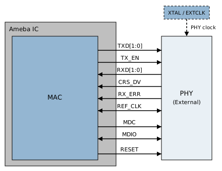
MAC to PHY Wiring
MAC to MAC
Two chips that each have a MAC are interconnected directly through RMII. No PHY is needed, MDC/MDIO is not connected, and Ameba works in PHY mode. The signal connections are shown below:
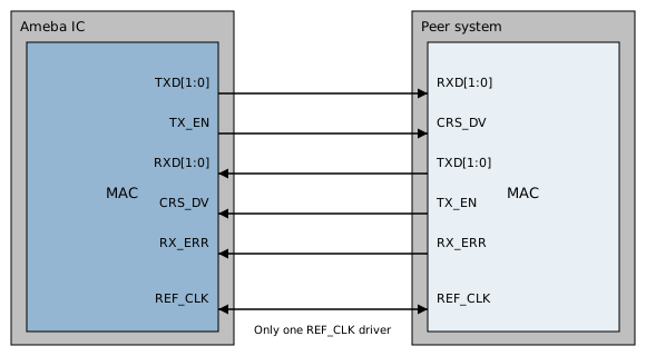
MAC to MAC Signal Connections
Warning
MAC to MAC Precautions
Disable auto-negotiation and force the same speed and duplex mode on both ends.
Cross-connect TX and RX between the two ends.
Both RMII interfaces must share the same 50 MHz reference clock, with only one REF_CLK driver.
Pin Configuration
The ameba_intfcfg.c file predefines 4 groups of Ethernet pin configurations (ETHERNET_PAD). Group 2 is used by default (it can be changed in Menuconfig, see the note below).
Pin Function |
Group 0 |
Group 1 |
Group 2 (Default) |
Group 3 |
|---|---|---|---|---|
RMII Signals |
(Fixed Set) |
(Fixed Set) |
(Fixed Set) |
(Fixed Set) |
REF_CLK |
PB_9 |
PB_18 |
PB_30 |
PB_18 |
TXD0 |
PB_8 |
PB_13 |
PB_29 |
PC_4 |
TXD1 |
PB_7 |
PB_16 |
PB_28 |
PC_3 |
TXEN |
PB_6 |
PB_15 |
PB_27 |
PC_2 |
RXD0 |
PB_11 |
PB_21 |
PC_0 |
PC_7 |
RXD1 |
PB_10 |
PB_19 |
PB_31 |
PC_6 |
RXERR |
PB_4 |
PB_17 |
PB_25 |
PB_17 |
CRS |
PB_5 |
PB_14 |
PB_26 |
PC_5 |
Mgmt & Clock |
||||
MDC |
PB_12 |
PB_22 |
PC_1 |
PA_25 |
MDIO |
PB_3 |
PB_23 |
PB_24 |
PA_26 |
EXTCLK |
PA_12 |
PB_24 |
PA_12 |
PB_19 |
The use of EXTCLK depends on the selected clock source scheme, see
Clock Source Schemes
.
Note
All pin assignments under the RMII interface are fixed. Users need to check the pinmux table and select an available pin group (0 - 3) in Menuconfig.
MDC, MDIO, and EXTCLK can be flexibly configured to other pins. Modify based on the pinmux table.