WHC Interface and Hardware Configuration
WHC Interface Connections
The pin connections between Ameba and Raspberry Pi are as follows:
Interface |
Ameba SoC pin |
Raspberry Pi GPIO |
Function |
|---|---|---|---|
SDIO |
PB6 |
GPIO 26 |
SDIO_DAT2 |
PB7 |
GPIO 27 |
SDIO_DAT3 |
|
PB8 |
GPIO 23 |
SDIO_CMD |
|
PB9 |
GPIO 22 |
SDIO_CLK |
|
PB13 |
GPIO 24 |
SDIO_DAT0 |
|
PB14 |
GPIO 25 |
SDIO_DAT1 |
|
SPI |
PB24 |
GPIO 10 |
SPI_MOSI |
PB25 |
GPIO 9 |
SPI_MISO |
|
PB23 |
GPIO 11 |
SPI_CLK |
|
PB26 |
GPIO 8 |
SPI_CS |
|
PB8 |
GPIO 23 |
DEV_TX_REQ |
|
PB9 |
GPIO 22 |
DEV_READY |
Interface |
Ameba SoC pin |
Raspberry Pi GPIO |
Function |
|---|---|---|---|
SPI |
PA29 |
GPIO 10 |
SPI_MOSI |
PA30 |
GPIO 9 |
SPI_MISO |
|
PA28 |
GPIO 11 |
SPI_CLK |
|
PA31 |
GPIO 8 |
SPI_CS |
|
PB2 |
GPIO 14 |
DEV_TX_REQ |
|
PB3 |
GPIO 15 |
DEV_READY |
Interface |
Ameba SoC pin |
Raspberry Pi GPIO |
Function |
|---|---|---|---|
SPI |
PA29 |
GPIO 10 |
SPI_MOSI |
PA30 |
GPIO 9 |
SPI_MISO |
|
PA28 |
GPIO 11 |
SPI_CLK |
|
PA31 |
GPIO 8 |
SPI_CS |
|
PB2 |
GPIO 14 |
DEV_TX_REQ |
|
PB3 |
GPIO 15 |
DEV_READY |
Interface |
Ameba SoC pin |
Raspberry Pi GPIO |
Function |
|---|---|---|---|
SPI |
PA29 |
GPIO 10 |
SPI_MOSI |
PA30 |
GPIO 9 |
SPI_MISO |
|
PA28 |
GPIO 11 |
SPI_CLK |
|
PA31 |
GPIO 8 |
SPI_CS |
|
PB2 |
GPIO 14 |
DEV_TX_REQ |
|
PB3 |
GPIO 15 |
DEV_READY |
Interface |
Ameba SoC pin |
Raspberry Pi GPIO |
Function |
|---|---|---|---|
SPI |
PA29 |
GPIO 10 |
SPI_MOSI |
PA30 |
GPIO 9 |
SPI_MISO |
|
PA28 |
GPIO 11 |
SPI_CLK |
|
PA31 |
GPIO 8 |
SPI_CS |
|
PB2 |
GPIO 14 |
DEV_TX_REQ |
|
PB3 |
GPIO 15 |
DEV_READY |
Interface |
Ameba SoC pin |
Raspberry Pi GPIO |
Function |
|---|---|---|---|
SDIO |
PA4 |
GPIO 26 |
SDIO_DAT2 |
PA21 |
GPIO 27 |
SDIO_DAT3 |
|
PA19 |
GPIO 23 |
SDIO_CMD |
|
PA18 |
GPIO 22 |
SDIO_CLK |
|
PA5 |
GPIO 24 |
SDIO_DAT0 |
|
PA20 |
GPIO 25 |
SDIO_DAT1 |
|
SPI |
PA30 |
GPIO 10 |
SPI_MOSI |
PA31 |
GPIO 9 |
SPI_MISO |
|
PA29 |
GPIO 11 |
SPI_CLK |
|
PB0 |
GPIO 8 |
SPI_CS |
|
PA24 |
GPIO 23 |
DEV_TX_REQ |
|
PA22 |
GPIO 22 |
DEV_READY |
Interface |
Ameba SoC pin |
Raspberry Pi GPIO |
Function |
|---|---|---|---|
SDIO |
PA7 |
GPIO 26 |
SDIO_DAT2 |
PA8 |
GPIO 27 |
SDIO_DAT3 |
|
PA9 |
GPIO 23 |
SDIO_CMD |
|
PA10 |
GPIO 22 |
SDIO_CLK |
|
PA11 |
GPIO 24 |
SDIO_DAT0 |
|
PA12 |
GPIO 25 |
SDIO_DAT1 |
|
SPI |
PA1 |
GPIO 10 |
SPI_MOSI |
PA2 |
GPIO 9 |
SPI_MISO |
|
PA0 |
GPIO 11 |
SPI_CLK |
|
PA3 |
GPIO 8 |
SPI_CS |
|
PA5 |
GPIO 23 |
DEV_TX_REQ |
|
PA4 |
GPIO 22 |
DEV_READY |
Note
SPI DEV_TX_REQ: Ameba notifies Host of pending data transmission via rising edge on this pin
SPI DEV_READY: Ameba status indicator
High level (1): Device ready to receive data
Low level (0): Device busy (pause transmission)
When connecting Ameba and Raspberry Pi pins with jumper wires, use wires as short as possible to minimize interference, crosstalk, and signal attenuation, thereby improving SPI communication stability.
Note
Default SDIO pins defined in Ameba SDK are used. If modification is required, adjust the SDIO_Pin_Grp parameter in the files below, which corresponds to the pinmux index in SDIO_PAD :
RTL8721Dx:file location:
component/soc/usrcfg/amebadplus/ameba_intfcfg.cRTL8721F:file location:
component/soc/usrcfg/amebagreen2/ameba_intfcfg.cRTL8720F:file location:
component/soc/usrcfg/RTL8720F/ameba_intfcfg.cHost-side SDIO interrupt requirements:
By default, SDIO_DATA1 is used.
If the Host does not support SDIO interrupts:
It can switch to polling mode for communication.
If the Host requires GPIO-based interrupts: The Ameba platform provides limited configurable GPIOs for this functionality. For detailed configurations and supported GPIO lists, currently request, please contact us.
Default configuration uses Ameba SDK predefined dedicated SPI pins. For custom pin configuration, refer to Pin Multiplexing Table to select pins and follow these steps below:
Dedicated Pin Configuration
Modify the corresponding code in
component/wifi/whc/whc_dev/spi/whc_spi_drv.h:
#elif defined (CONFIG_AMEBADPLUS)
#define PINMUX_FUNCTION_SPIS      PINMUX_FUNCTION_SPI
#define DEV_READY_PIN             _PB_9
#define RX_REQ_PIN                _PB_8
#define SPIS_MOSI                 _PB_24
#define SPIS_MISO                 _PB_25
#define SPIS_SCLK                 _PB_23
#define SPIS_CS                   _PB_26
#elif defined (CONFIG_AMEBALITE)
#define PINMUX_FUNCTION_SPIS      PINMUX_FUNCTION_SPI
#define DEV_READY_PIN             _PB_3
#define RX_REQ_PIN                _PB_2
#define SPIS_MOSI                 _PA_29
#define SPIS_MISO                 _PA_30
#define SPIS_SCLK                 _PA_28
#define SPIS_CS                   _PA_31
#ifdef CONFIG_AMEBAGREEN2
#define PINMUX_FUNCTION_SPIS     PINMUX_FUNCTION_SPI0
#define DEV_READY_PIN                                _PA_22
#define DEV_TX_REQ_PIN                               _PA_24
#define SPIS_MOSI                _PA_30
#define SPIS_MISO                _PA_31
#define SPIS_SCLK                _PA_29
#define SPIS_CS                  _PB_0
#ifdef CONFIG_RTL8720F
#define PINMUX_FUNCTION_SPIS     PINMUX_FUNCTION_SPI0
#define DEV_READY_PIN            _PA_4
#define DEV_TX_REQ_PIN           _PA_5
#define SPIS_MOSI                _PA_1
#define SPIS_MISO                _PA_2
#define SPIS_SCLK                _PA_0
#define SPIS_CS                  _PA_3
If switching to SPI1 (SDK uses SPI0 as the default), modify the following code in the same file:
#define WHC_SPI_DEV               SPI0_DEV
#define SPIS_IRQ                  SPI0_IRQ
#define WHC_SPI_DEV               SPI0_DEV
#define SPIS_IRQ                  SPI0_IRQ
#define WHC_SPI_DEV               SPI0_DEV
#define SPIS_IRQ                  SPI0_IRQ
#define WHC_SPI_DEV               SPI0_DEV
#define SPIS_IRQ                  SPI0_IRQ
#define WHC_SPI_DEV               SPI0_DEV
#define SPIS_IRQ                  SPI0_IRQ
#ifdef CONFIG_AMEBAGREEN2
#define PINMUX_FUNCTION_SPIS     PINMUX_FUNCTION_SPI0
#define DEV_READY_PIN                                _PA_22
#define DEV_TX_REQ_PIN                               _PA_24
#define SPIS_MOSI                _PA_30
#define SPIS_MISO                _PA_31
#define SPIS_SCLK                _PA_29
#define SPIS_CS                  _PB_0
#define WHC_SPI_DEV               SPI0_DEV
#define SPIS_IRQ                  SPI0_IRQ
#ifdef CONFIG_RTL8720F
#define PINMUX_FUNCTION_SPIS     PINMUX_FUNCTION_SPI0
#define DEV_READY_PIN            _PA_4
#define DEV_TX_REQ_PIN           _PA_5
#define SPIS_MOSI                _PA_1
#define SPIS_MISO                _PA_2
#define SPIS_SCLK                _PA_0
#define SPIS_CS                  _PA_3
#define WHC_SPI_DEV               SPI0_DEV
#define SPIS_IRQ                  SPI0_IRQ
Full-matrix Pin Configuration
For differences between dedicated pins and full-matrix pins, refer to Function Multiplexing .
When using full-matrix pins, after completing the above Dedicated Pin configuration:
In
component/wifi/whc/whc_dev/spi/whc_spi_drv.c, modify thePinFuncIDparameter ofPinmux_Config(PinName, PinFuncID)to match full matrix signal IDs:
void whc_spi_dev_device_init(void)
{
   ...
   /* Initialize SPI */
   Pinmux_Config(SPIS_MOSI, PINMUX_FUNCTION_SPIS);//MOSI
   Pinmux_Config(SPIS_MISO, PINMUX_FUNCTION_SPIS);//MISO
   Pinmux_Config(SPIS_SCLK, PINMUX_FUNCTION_SPIS);//CLK
   Pinmux_Config(SPIS_CS, PINMUX_FUNCTION_SPIS);//CS
   PAD_PullCtrl(SPIS_CS, GPIO_PuPd_UP);  // pull-up, default 1
   PAD_PullCtrl(SPIS_SCLK, GPIO_PuPd_DOWN);
   ...
}
Adjust host frequency (refer to SPI Peripheral for full-matrix pins requirements)
File path: component/wifi/whc/whc_host_linux/driver/spi/spidev-overlay.dts
fragment@3 {
   target = <&spi0>;
   __overlay__ {
            status = "okay";
            #address-cells = <1>;
            #size-cells = <0>;
            inic_spi: inic_spi@0 {
            compatible = "realtek,inic";
            reg = <0>;
            spi-max-frequency = <30000000>;
            status = "okay";
         };
   };
};
File path: component/wifi/whc/whc_host_rtos/spi/whc_spi_host.h
#elif defined (CONFIG_AMEBALITE)
#define PINMUX_FUNCTION_SPIM      PINMUX_FUNCTION_SPI
#define DEV_READY_PIN             _PB_3
#define RX_REQ_PIN                _PB_2
#define SPIM_MOSI                 _PA_29
#define SPIM_MISO                 _PA_30
#define SPIM_SCLK                 _PA_28
#define HOST_READY_PIN            _PA_31
#define SPI_CLOCK_DIVIDER         6   // 120M clock source according to spi_get_ipclk
Configuration Example
Using RTL8713E as example, select full-matrix pins from Pin Multiplexing Table:
SoC pin |
PinFuncID |
|---|---|
PA_21 |
SPI1_MOSI |
PA_12 |
SPI1_MISO |
PA_11 |
SPI1_MISO |
PA_23 |
SPI1_CS |
Update SPI configuration in
component/wifi/whc/whc_dev/spi/whc_spi_drv.h:
#define SPIS_MOSI                 _PA_21
#define SPIS_MISO                 _PA_12
#define SPIS_SCLK                 _PA_11
#define SPIS_CS                   _PA_23
#define WHC_SPI_DEV               SPI1_DEV
#define SPIS_IRQ                  SPI1_IRQ
Update pin multiplexing in
component/wifi/whc/whc_dev/spi/whc_spi_drv.c:
void whc_spi_dev_device_init(void)
{
   ...
   /* Initialize SPI */
   Pinmux_Config(SPIS_MOSI, PINMUX_FUNCTION_SPI1_MOSI);//MOSI
   Pinmux_Config(SPIS_MISO, PINMUX_FUNCTION_SPI1_MISO);//MISO
   Pinmux_Config(SPIS_SCLK, PINMUX_FUNCTION_SPI1_CLK);//CLK
   Pinmux_Config(SPIS_CS, PINMUX_FUNCTION_SPI1_CS);//CS
   PAD_PullCtrl(SPIS_CS, GPIO_PuPd_UP);  // pull-up, default 1
   PAD_PullCtrl(SPIS_SCLK, GPIO_PuPd_DOWN);
   ...
}
Host frequency adjustment examples:
File path: component/wifi/whc/whc_host_linux/driver/spi/spidev-overlay.dts
fragment@3 {
   target = <&spi0>;
   __overlay__ {
            status = "okay";
            #address-cells = <1>;
            #size-cells = <0>;
            inic_spi: inic_spi@0 {
            compatible = "realtek,inic";
            reg = <0>;
            spi-max-frequency = <10000000>;
            status = "okay";
         };
   };
};
File path: component/wifi/whc/whc_host_rtos/spi/whc_spi_host.h
#elif defined (CONFIG_AMEBALITE)
#define PINMUX_FUNCTION_SPIM      PINMUX_FUNCTION_SPI
#define DEV_READY_PIN             _PB_3
#define RX_REQ_PIN                _PB_2
#define SPIM_MOSI                 _PA_29
#define SPIM_MISO                 _PA_30
#define SPIM_SCLK                 _PA_28
#define HOST_READY_PIN            _PA_31
#define SPI_CLOCK_DIVIDER         12   // 120M clock source according to spi_get_ipclk
WHC SDIO Adapter Board
Realtek provides adapter board that enables convenient connection to mini SD card slots. It is recommended to use dedicated adapter boards for interfacing with SDIO pins.
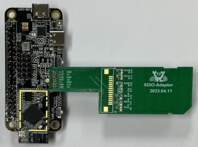
WHC SDIO adapter board (physical diagram)
Note
Realtek official adapter boards will be available soon. Currently request samples, please contact us.
WHC Raspberry Pi Direct Connection
For high-speed scenarios, directly solder Ameba SDIO pins to Raspberry Pi GPIO.
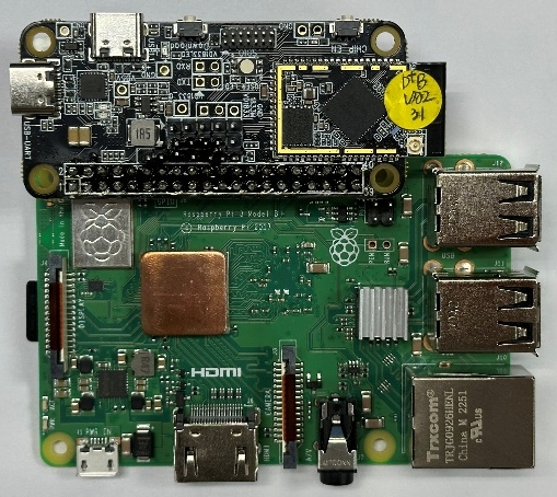
Ameba-Raspberry Pi direct connection diagram
