Wi-Fi R-Mesh Introduction
Video Resource
Wi-Fi R-Mesh Topology
As shown in the figure below, Wi-Fi R-Mesh is a tree-topology mesh network used to increase the Wi-Fi coverage, allowing stations that are far from the AP to also obtain a stable network connection.

Wi-Fi R-Mesh topology
Wi-Fi R-Mesh Advantage
The well-designed Wi-Fi R-Mesh has the following advantages:
A software-unsensible mesh network:
All Mesh protocols are implemented at Wi-Fi driver layer. Both root nodes and child nodes are regarded by the application as standard Wi-Fi stations connected to the AP.
Rapid pairing and switching within hundreds of microseconds:
Child nodes can quickly switch to a new parent node with better signal quality without interrupting data communication.
If the parent node encounters a problem (such as power off or hang), the child node can rapidly detect the issue and switch to an alternative parent node without interrupting data communication.
A node can migrate all its child nodes to a new parent node while maintaining uninterrupted data flow.
High throughput across multiple hops:
R-Mesh forwarding bypasses the TCP/IP protocol stack, operating directly at the driver layer, utilizing less RAM and MCU resources.
With extremely short software processing time, better throughput can be achieved.
Network stability:
Simplified software architecture eliminates complex routing table algorithms, ensuring network stability.
Traditional mesh network issues like loops do not occur.
Wi-Fi R-Mesh Data Flow
Wi-Fi R-Mesh handles data forwarding directly at the Wi-Fi driver layer, requiring less RAM and MCU resources.
Due to the minimal software processing involved, nodes maintain good throughput even after several hops.

Wi-Fi R-Mesh data flow
Wi-Fi R-Mesh Root Node Capacity
The Root Node Capacity of Wi-Fi R-Mesh refers to the maximum number of child nodes that can be connected to a root node.
The Wi-Fi R-Mesh topology diagram illustrates an example where the Root Node Capacity is 4. Each root node can support up to 4 child nodes regardless of the topology.
Topology 0 (Root Sta 0): All child nodes are directly connected to the root node.
Topology 3 (Root Sta 3): The four nodes form a 4-hop linear network.
Can also be any other topologies between Topology 0 and Topology 3
Wi-Fi R-Mesh topology diagram (Root Node Capacity = 4)
The Root Node Capacity of Wi-Fi R-Mesh is 4
The Root Node Capacity of Wi-Fi R-Mesh is 32
Wi-Fi R-Mesh NAT (R-NAT)
In R-Mesh, if all nodes establish Wi‑Fi connections directly with the AP, the network size will be limited by the maximum number of stations the AP can support, which is referred to as the AP capacity.
To expand the number of accessible nodes, a Station + SoftAP + NAT architecture can be introduced: some nodes (referred to as R-NAT nodes) connect to the AP and provide a SoftAP for other nodes to access, while also being responsible for forwarding data between the AP network and the R-Mesh network through NAT.
As illustrated in the figure below, the R-NAT node is positioned between the root node and the AP to extend the number of nodes that can access the network.

Wi-Fi R-NAT
The R-NAT Node Capacity refers to the number of nodes that the R-NAT node’s SoftAP can connect to. It is controlled by the ap_sta_num parameter. For details, see
R-Mesh Programming Interface
.
The R-Mesh Network Capacity refers to the total number of nodes that can join the R-Mesh network. The determining factors differ depending on whether R-NAT nodes are deployed:
Scenario |
Network Capacity |
|---|---|
Without R-NAT |
Limited by AP capacity |
With R-NAT |
Can exceed AP capacity, determined by R-NAT node capacity and the number of R-NAT nodes |
Root Node Capacity is a topology constraint that limits the number of nodes under a single root node, and is not related to the overall network capacity.
Wi-Fi R-Mesh Throughput
Throughput Test
Similar to the regular Station or AP mode, we can test the throughput of R-Mesh via iperf command. As shown in the diagram below, simply input the iperf commands on the PC at the AP side and the node side.

R-Mesh throughput test
At R-Mesh node side, input the following AT command via UART:
AT+IPERF=-c,<server IP>,-i,<periodic>,-u,-b,<bandwidth>,-t,<transtime>,-p,<port>
At AP side (normally a PC), input the following iperf command via Terminal:
iperf -s -i <periodic> -u -p <port>
At R-Mesh node side, input the following AT command via UART:
AT+IPERF=-s,-i,<periodic>,-u,-p,<port>
At AP side (normally a PC), input the following iperf command via Terminal:
iperf -c <R-mesh node IP> -i <periodic> -u -b <bandwidth> -t <transtime> -p <port>
At R-Mesh node side, input the following AT command via UART:
AT+IPERF=-c,<server IP>,-i,<periodic>,-t,<transtime>,-p,<port>
At AP side (normally a PC), input the following iperf command via Terminal:
iperf -s -i <periodic> -p <port>
At R-Mesh node side, input the following AT command via UART:
AT+IPERF=-s,-i,<periodic>,-p,<port>
At AP side (normally a PC), input the following iperf command via Terminal:
iperf -c <R-mesh node IP> -i <periodic> -t <transtime> -p <port>
Throughput
The throughput data of Wi-Fi R-Mesh is shown in the following table:
(Single Node indicates nodes at each hierarchical level conduct throughput testing separately; L1 + L2 indicates L1 and L2 nodes conduct throughput testing simultaneously; Other scenarios follow the same pattern)
Test scenario |
Layer |
UDP Tx (Mbps) |
UDP Rx (Mbps) |
TCP Tx (Mbps) |
TCP Rx (Mbps) |
|---|---|---|---|---|---|
Single Node |
Layer1 |
39.5 |
27.2 |
27.5 |
22.3 |
Layer2 |
19.4 |
15.6 |
14.4 |
12 |
|
Layer3 |
12.5 |
9.73 |
9.25 |
8.23 |
|
Layer4 |
9.36 |
7.6 |
7.18 |
5.66 |
|
Layer5 |
7.53 |
6.23 |
5.37 |
4.45 |
|
L1 + L2 |
Layer1 |
13.3 |
9.67 |
10.1 |
8.19 |
Layer2 |
12.5 |
9.66 |
9.43 |
8 |
|
L1 + L2 + L3 |
Layer1 |
6.21 |
5.07 |
5 |
4.24 |
Layer2 |
6.15 |
5.05 |
4.81 |
4.12 |
|
Layer3 |
6.02 |
5.04 |
4.88 |
4.04 |
|
L1 + L2 + L3 + L4 |
Layer1 |
3.77 |
2.88 |
2.89 |
2.58 |
Layer2 |
3.48 |
2.88 |
2.92 |
2.52 |
|
Layer3 |
3.41 |
2.88 |
2.91 |
2.47 |
|
Layer4 |
3.23 |
2.88 |
2.89 |
2.36 |
|
L1 + L2 + L3 + L4 + L5 |
Layer1 |
2.94 |
2.2 |
1.86 |
1.57 |
Layer2 |
2.89 |
1.97 |
1.85 |
1.58 |
|
Layer3 |
2.4 |
1.97 |
1.83 |
1.54 |
|
Layer4 |
2.03 |
1.95 |
1.85 |
1.54 |
|
Layer5 |
2.19 |
2.18 |
1.81 |
1.47 |
Test conditions:
Image2 running on PSRAM
The channel bandwidth is 20 MHz
Enable the
Enable HIGH TPoption in theCONFIG WIFIsection of the Menuconfig main pageAP:ASUS RT-AX88U
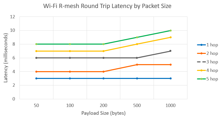
Wi-Fi R-Mesh RTT
Unlike BLE and ZigBee, R-Mesh has a very low Round-Trip Time (RTT) and and it does not significantly increase even as packet size increases.
Wi-Fi R-Mesh Memory Size
Compared with devices in normal STA mode, devices with the R-Mesh feature enabled require additional memory consumption as shown in the table below:
Item |
KM0 |
KM4 |
|---|---|---|
txt |
25KB |
0.5KB |
rodata |
2.3KB |
0.1KB |
data+bss |
0.5KB |
<0.1KB |
heap |
20KB + N * 0.2KB [1] |
0.2KB |
[1] N denotes the number of other nearby R‑Mesh nodes discovered by this R‑Mesh node (excluding its own child nodes).
Compared with devices in normal STA mode, devices with the R-NAT feature enabled require additional memory consumption as shown in the table below:
Item |
KM0 |
KM4 |
|---|---|---|
txt |
25KB |
14KB |
rodata |
2.3KB |
2.7KB |
data+bss |
0.5KB |
0.2KB |
heap |
23KB + N * 1.9KB [1] |
25KB + N * 1.4KB [2] |
[1][2] N denotes the number of R-Mesh nodes connected to this R-NAT node.
If you need to use the visualization tool ( Gravitation or MGravitation ), you must enable the R-Mesh Socket feature. The R-Mesh Socket feature requires additional memory on top of the R-Mesh/R-NAT feature as follows:
Item |
KM0 |
KM4 |
|---|---|---|
txt |
0.8KB |
1.8KB |
rodata |
<0.1KB |
0.2KB |
data+bss |
0 |
0.2KB |
heap |
0 |
7KB |
