Wi-Fi R-Mesh Function Verification
This section demonstrates how to establish an R-Mesh network and achieve data communication between nodes. This example will help you become familiar with the basic usage of R-Mesh.
Please first enable R-Mesh and Socket according to the instructions in SDK Configuration , then compile and flash the firmware.
Gravitation(Visualization Tool)
To visually display R-Mesh node topology, we provide the Gravitation tool. Please refer to Gravitation for configuration.
Join the Network
Method 1: Use ATCMD to add all nodes to the network.
AT+WLCONN=ssid,rmesh_test,pw,12345678
Method 2: Use RPP (R-mesh Provision Protocol) to join network. Please refer to ZRPP
Topology Display
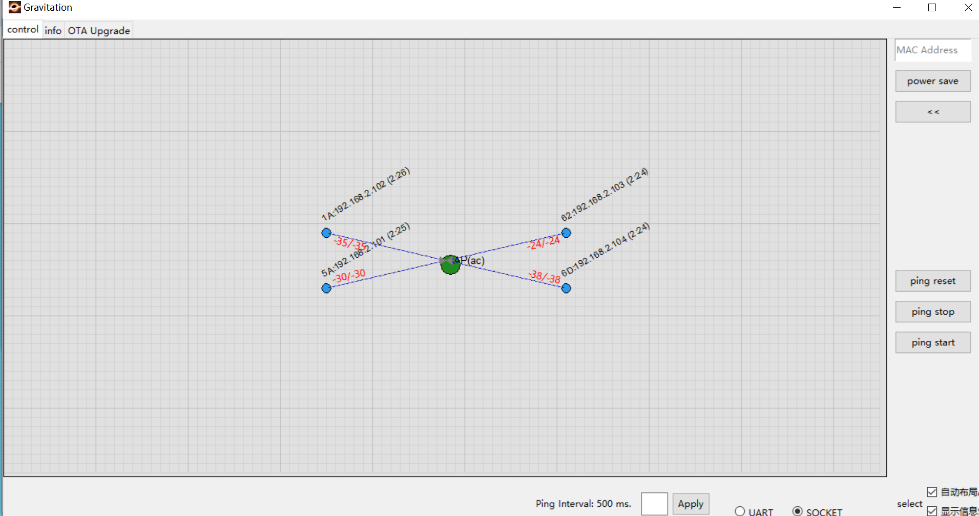
After joining the network, nodes automatically send information to the Gravitation tool. The following figure shows 4 nodes successfully connected to the AP.
Basic information appears above each node is: MAC_Addr[5]:IP(update_time).
Example: The node in the top-left corner shows: 1A:192.168.2.102(2:26) which means:
MAC Address:
XX:XX:XX:XX:0x1AIP Address:
192.168.2.102
For more details, please refer to Gravitation .
Note
While the tool displays node connection relationships, it cannot reflect physical locations. You may:
Disable Auto Layout in the bottom-right corner
Manually drag nodes to match their real-world positions
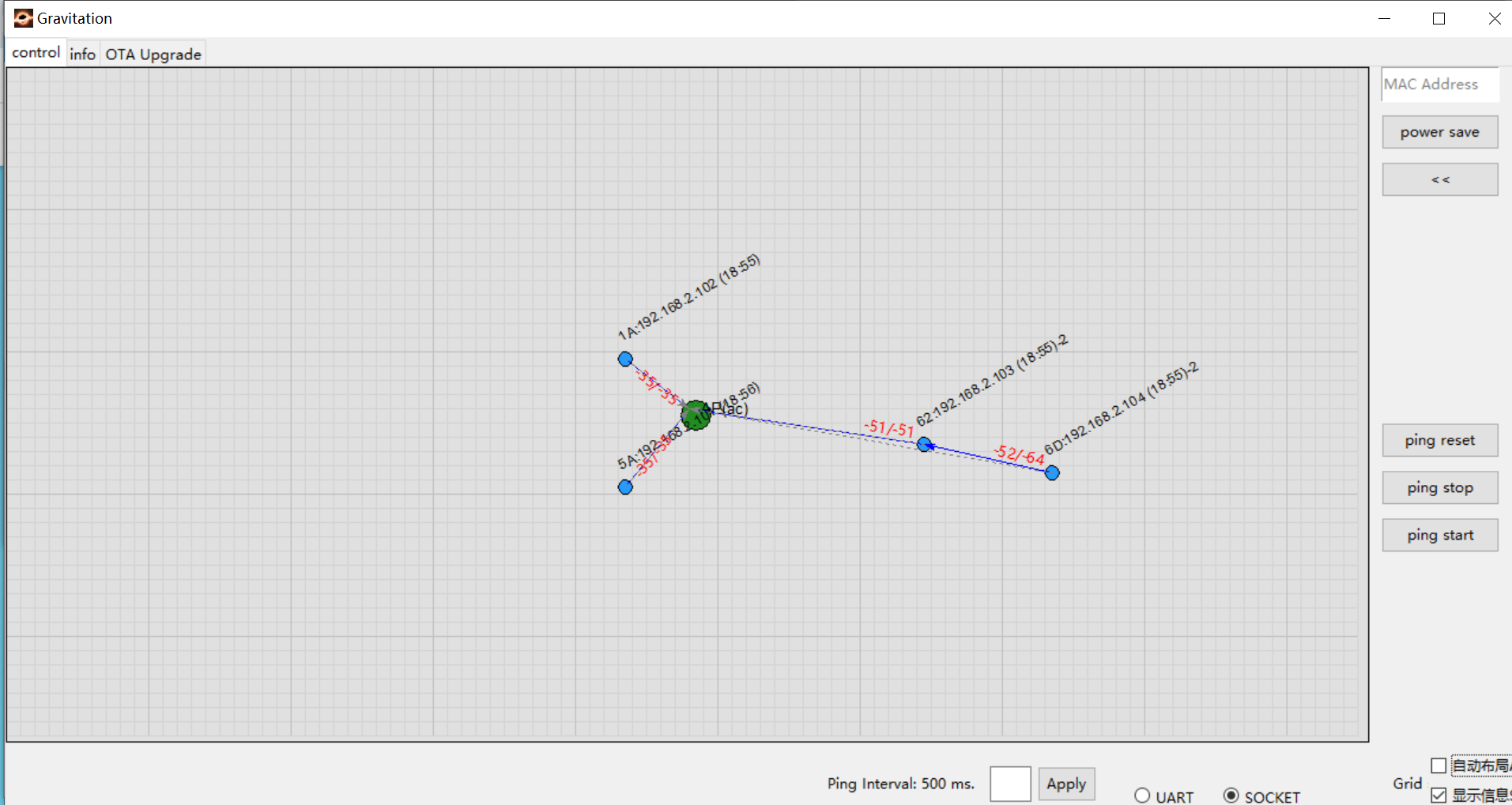
Switch Verification
To verify switch behavior:
Physically move two nodes away from the AP (e.g., node 62 and node 6D shown on the right)
Observe that node 6D automatically switches its connection to node 62 when AP’s RSSI is worse than node 62
Communication Verification
Method 1: Execute the Ping command on any node
AT+PING=192.168.2.102
Method 2: Use Gravitation Tool’s Ping Test Function
The tool conveniently initiates ping tests for all nodes:
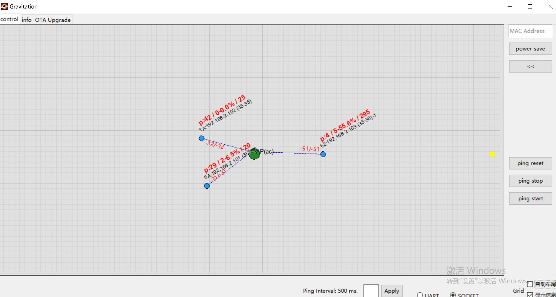
Ping log appears above each node is: Ping: Successful packets/Failed packets - Packet loss rate/RTT
Example: The node in the down-left corner shows: P:29/2-6.5%/20 which means:
29 successful packets
2 failed packets
6.5% packet loss rate
RTT of 20 ms
