Symmetric Encryption Engine
Overview
The Symmetric Hardware Crypto Engine is a hardware acceleration module integrated into the SoC, designed to perform AES encryption and HMAC hashing operations. Compared to software-based implementations, the hardware crypto engine offers the following advantages:
High Performance: Hardware parallel computation significantly accelerates encryption and decryption speeds.
Low Power Consumption: Dedicated circuitry reduces CPU involvement, lowering overall power consumption.
High Security: Keys are stored in the OTP region and cannot be directly accessed by software; TrustZone isolation is supported.
Reduced CPU Overhead: In DMA mode, the engine autonomously handles data transfer and computation, freeing up CPU resources.
The AES and HMAC algorithms implemented in this engine are NIST CAVP certified, supporting multiple cryptographic algorithms and operating modes. It is widely used in security-critical scenarios such as data encryption, secure boot, and firmware protection.
Operating Principles
The crypto engine adopts a hardware bus architecture and interacts with the system through either a DMA controller or the APB bus:
DMA Mode: The engine’s internal DMA controller directly accesses memory and autonomously handles data fetching, computation, and result write-back, making it suitable for large-volume encryption and decryption.
Slave Mode: The CPU writes data into the engine’s FIFO via the APB bus, making it suitable for small-volume operations.
The engine supports TrustZone technology, automatically identifying the CPU’s security state (Secure/Non-Secure) and employing a hardware mutex mechanism to prevent conflicts caused by simultaneous access from secure and non-secure domains. Each time the lock is released, the engine automatically clears sensitive information from its registers to prevent side-channel attacks.
AES Engine
The AES engine encrypts or decrypts data according to the Advanced Encryption Standard (AES) defined by NIST, supporting automatic message padding. It supports both software register keys and hardware OTP keys. Hardware encryption/decryption reduces software overhead, lowers CPU and memory resource consumption, and operates faster and more securely than software implementations.
AES Algorithm Support
Supported key sizes: AES-128, AES-192, AES-256
Supported encryption/decryption modes:
ECB (Electronic Codebook)
CBC (Cipher Block Chaining)
OFB (Output Feedback)
CFB (Cipher Feedback)
CTR (Counter)
GCM (Galois/Counter)
Supported key sizes: AES-128, AES-192, AES-256
Supported encryption/decryption modes:
ECB (Electronic Codebook)
CBC (Cipher Block Chaining)
OFB (Output Feedback)
CFB (Cipher Feedback)
CTR (Counter)
GCM (Galois/Counter)
Supported key sizes: AES-128, AES-192, AES-256
Supported encryption/decryption modes:
ECB (Electronic Codebook)
CBC (Cipher Block Chaining)
OFB (Output Feedback)
CFB (Cipher Feedback)
CTR (Counter)
GCM (Galois/Counter)
Supported key sizes: AES-128, AES-192, AES-256
Supported encryption/decryption modes:
ECB (Electronic Codebook)
CBC (Cipher Block Chaining)
OFB (Output Feedback)
CFB (Cipher Feedback)
CTR (Counter)
GCM (Galois/Counter)
Supported key sizes: AES-128, AES-192, AES-256
Supported encryption/decryption modes:
ECB (Electronic Codebook)
CBC (Cipher Block Chaining)
OFB (Output Feedback)
CFB (Cipher Feedback)
CTR (Counter)
GCM (Galois/Counter)
Supported key sizes: AES-128, AES-192, AES-256
Supported encryption/decryption modes:
ECB (Electronic Codebook)
CBC (Cipher Block Chaining)
OFB (Output Feedback)
CFB (Cipher Feedback)
CTR (Counter)
GCM (Galois/Counter)
The engine algorithm has been NIST CAVP certified.
Supported key sizes: AES-128, AES-192, AES-256
Supported encryption/decryption modes:
ECB (Electronic Codebook)
CBC (Cipher Block Chaining)
OFB (Output Feedback)
CFB (Cipher Feedback)
CTR (Counter)
GCM (Galois/Counter)
XTS (XEX-based Tweaked CodeBook mode with CipherText Stealing)
Supported message authentication codes:
GMAC (Galois Message Authentication Code)
CMAC (Cipher Block Chaining-Message Authentication Code)
AES Algorithms
Supported key sizes: AES-128, AES-192, AES-256
Supported encryption/decryption modes:
ECB (Electronic Codebook)
CBC (Cipher Block Chaining)
OFB (Output Feedback)
CFB (Cipher Feedback)
CTR (Counter)
GCM (Galois/Counter)
CCM (Counter with CBC-MAC)
Supported message authentication codes:
GMAC (Galois Message Authentication Code)
CMAC (Cipher Block Chaining-Message Authentication Code)
SM4 Algorithms
Supported key sizes: SM4-128
Supported encryption/decryption modes:
ECB (Electronic Codebook)
CBC (Cipher Block Chaining)
OFB (Output Feedback)
CFB (Cipher Feedback)
CTR (Counter)
GCM (Galois/Counter)
CCM (Counter with CBC-MAC)
Supported message authentication codes:
GMAC (Galois Message Authentication Code)
CMAC (Cipher Block Chaining-Message Authentication Code)
Note
SM4 and AES use the same hardware engine; the algorithm core is selected via the CORE_SEL bit.
The engine algorithm has been NIST CAVP certified.
Supported key sizes: AES-128, AES-192, AES-256
Supported encryption/decryption modes:
ECB (Electronic Codebook)
CBC (Cipher Block Chaining)
OFB (Output Feedback)
CFB (Cipher Feedback)
CTR (Counter)
GCM (Galois/Counter)
XTS (XEX-based Tweaked CodeBook mode with CipherText Stealing)
Supported message authentication codes:
GMAC (Galois Message Authentication Code)
CMAC (Cipher Block Chaining-Message Authentication Code)
AES Keys
The AES engine features an independent key management unit. This unit supports both software keys and hardware OTP keys.
The hardware encryption engine provides two key loading methods:
Software transfer: Keys are dynamically passed in by the application (software accessible)
OTP automatic loading: Keys are pre-burned into the OTP physical storage area (not accessible by software, only accessible by the encryption engine, preventing tampering or reading)
The OTP physical storage area supports storing 6 sets of keys, which need to be burned through the efuse command.
Engine Type |
Security |
Key Index |
OTP Key |
|---|---|---|---|
AES |
Secure |
0 |
S_IPSEC_Key1 |
AES |
Secure |
1 |
S_IPSEC_Key2 |
AES |
Secure |
2 |
RSIP_AES_Key1 |
AES |
Secure |
3 |
RSIP_AES_Key2 |
AES |
Non-secure |
0 |
NS_IPSEC_Key1 |
AES |
Non-secure |
1 |
NS_IPSEC_Key2 |
AES |
Non-secure |
2 |
RSIP_AES_Key1 |
AES |
Non-secure |
3 |
RSIP_AES_Key2 |
Note
In the table above, the AES engine lists 4 key indexes each for the Secure and Non-secure sides (8 entries in total). However, RSIP_AES_Key1 and RSIP_AES_Key2 on the Secure side and the Non-secure side actually refer to the same OTP physical keys — they are auto-loaded by both the secure and non-secure AES engines, rather than being two independent sets. After removing the duplicates, the OTP physical storage area in fact holds only 6 distinct sets of keys (S_IPSEC_Key1/Key2, NS_IPSEC_Key1/Key2, RSIP_AES_Key1/Key2), which is exactly why the text above states that the OTP physical storage area can store 6 sets of keys.
The detailed functions of OTP keys are shown below:
OTP Key Name |
Address |
Size bits |
Default Value |
Description |
|---|---|---|---|---|
S_IPSEC_Key1 (RDP) |
Logical map 0x200 |
256 |
0xFF |
When OTPKey_init function is enabled, the secure encryption engine will automatically load this key for HMAC or AES algorithm |
S_IPSEC_Key2 (Secure boot HMAC) |
Logical map 0x220 |
256 |
0xFF |
|
NS_IPSEC_Key1 |
Logical map 0x240 |
256 |
0xFF |
When OTPKey_init function is enabled, the non-secure encryption engine will automatically load this key for HMAC or AES algorithm |
NS_IPSEC_Key2 |
Logical map 0x260 |
256 |
0xFF |
|
RSIP_AES_Key1 |
Logical map 0x2c0 |
256 |
0xFF |
When OTPKey_init function is enabled, non-secure AES engine and secure AES engine will automatically load this key for AES algorithm |
RSIP_AES_Key2 |
Logical map 0x2e0 |
256 |
0xFF |
|
S_IPSEC_Key1_Read_Protection |
Physical map 0x365[3] |
1 |
1 |
0: Enable S_IPSEC_Key1 read protection, prohibit key from being read 1: Disable S_IPSEC_Key1 read protection |
S_IPSEC_Key1_Write_Protection |
Physical map 0x365[4] |
1 |
1 |
0: Enable S_IPSEC_Key1 write protection, prohibit key from being written to all 0s by hackers 1: Disable S_IPSEC_Key1 write protection |
S_IPSEC_Key2_Read_Protection |
Physical map 0x365[5] |
1 |
1 |
0: Enable S_IPSEC_Key2 read protection, prohibit key from being read 1: Disable S_IPSEC_Key2 read protection |
S_IPSEC_Key2_Write_Protection |
Physical map 0x365[6] |
1 |
1 |
0: Enable S_IPSEC_Key2 write protection, prohibit key from being written to all 0s by hackers 1: Disable S_IPSEC_Key2 write protection |
RSIP_AES_Key1_Read_Protection |
Physical map 0x366[7] |
1 |
1 |
0: Enable RSIP_AES_Key1 read protection, prohibit key from being read 1: Disable RSIP_AES_Key1 read protection |
RSIP_AES_Key1_Write_Protection |
Physical map 0x367[0] |
1 |
1 |
0: Enable RSIP_AES_Key1 write protection, prohibit key from being written to all 0s by hackers 1: Disable RSIP_AES_Key1 write protection |
RSIP_AES_Key2_Read_Protection |
Physical map 0x367[1] |
1 |
1 |
0: Enable RSIP_AES_Key2 read protection, prohibit key from being read 1: Disable RSIP_AES_Key2 read protection |
RSIP_AES_Key2_Write_Protection |
Physical map 0x367[2] |
1 |
1 |
0: Enable RSIP_AES_Key2 write protection, prohibit key from being written to all 0s by hackers 1: Disable RSIP_AES_Key2 write protection |
The hardware encryption engine provides two key loading methods:
Software transfer: Keys are dynamically passed in by the application (software accessible)
OTP automatic loading: Keys are pre-burned into the OTP physical storage area (not accessible by software, only accessible by the encryption engine, preventing tampering or reading)
The OTP physical storage area supports storing 6 sets of keys, which need to be burned through the efuse command.
Engine Type |
Security |
Key Index |
OTP Key |
|---|---|---|---|
AES |
Secure |
0 |
S_IPSEC_Key1 |
AES |
Secure |
1 |
S_IPSEC_Key2 |
AES |
Secure |
2 |
RSIP_AES_Key1 |
AES |
Secure |
3 |
RSIP_AES_Key2 |
AES |
Non-secure |
0 |
NS_IPSEC_Key1 |
AES |
Non-secure |
1 |
NS_IPSEC_Key2 |
AES |
Non-secure |
2 |
RSIP_AES_Key1 |
AES |
Non-secure |
3 |
RSIP_AES_Key2 |
Note
In the table above, the AES engine lists 4 key indexes each for the Secure and Non-secure sides (8 entries in total). However, RSIP_AES_Key1 and RSIP_AES_Key2 on the Secure side and the Non-secure side actually refer to the same OTP physical keys — they are auto-loaded by both the secure and non-secure AES engines, rather than being two independent sets. After removing the duplicates, the OTP physical storage area in fact holds only 6 distinct sets of keys (S_IPSEC_Key1/Key2, NS_IPSEC_Key1/Key2, RSIP_AES_Key1/Key2), which is exactly why the text above states that the OTP physical storage area can store 6 sets of keys.
The detailed functions of OTP keys are shown below:
OTP Key Name |
Address |
Size bits |
Default Value |
Description |
|---|---|---|---|---|
S_IPSEC_Key1 (RDP) |
Logical map 0x200 |
256 |
0xFF |
When OTPKey_init function is enabled, the secure encryption engine will automatically load this key for HMAC or AES algorithm |
S_IPSEC_Key2 (Secure boot HMAC) |
Logical map 0x220 |
256 |
0xFF |
|
NS_IPSEC_Key1 |
Logical map 0x240 |
256 |
0xFF |
When OTPKey_init function is enabled, the non-secure encryption engine will automatically load this key for HMAC or AES algorithm |
NS_IPSEC_Key2 |
Logical map 0x260 |
256 |
0xFF |
|
RSIP_AES_Key1 |
Logical map 0x2c0 |
256 |
0xFF |
When OTPKey_init function is enabled, non-secure AES engine and secure AES engine will automatically load this key for AES algorithm |
RSIP_AES_Key2 |
Logical map 0x2e0 |
256 |
0xFF |
|
S_IPSEC_Key1_Read_Protection |
Physical map 0x365[3] |
1 |
1 |
0: Enable S_IPSEC_Key1 read protection, prohibit key from being read 1: Disable S_IPSEC_Key1 read protection |
S_IPSEC_Key1_Write_Protection |
Physical map 0x365[4] |
1 |
1 |
0: Enable S_IPSEC_Key1 write protection, prohibit key from being written to all 0s by hackers 1: Disable S_IPSEC_Key1 write protection |
S_IPSEC_Key2_Read_Protection |
Physical map 0x365[5] |
1 |
1 |
0: Enable S_IPSEC_Key2 read protection, prohibit key from being read 1: Disable S_IPSEC_Key2 read protection |
S_IPSEC_Key2_Write_Protection |
Physical map 0x365[6] |
1 |
1 |
0: Enable S_IPSEC_Key2 write protection, prohibit key from being written to all 0s by hackers 1: Disable S_IPSEC_Key2 write protection |
RSIP_AES_Key1_Read_Protection |
Physical map 0x366[7] |
1 |
1 |
0: Enable RSIP_AES_Key1 read protection, prohibit key from being read 1: Disable RSIP_AES_Key1 read protection |
RSIP_AES_Key1_Write_Protection |
Physical map 0x367[0] |
1 |
1 |
0: Enable RSIP_AES_Key1 write protection, prohibit key from being written to all 0s by hackers 1: Disable RSIP_AES_Key1 write protection |
RSIP_AES_Key2_Read_Protection |
Physical map 0x367[1] |
1 |
1 |
0: Enable RSIP_AES_Key2 read protection, prohibit key from being read 1: Disable RSIP_AES_Key2 read protection |
RSIP_AES_Key2_Write_Protection |
Physical map 0x367[2] |
1 |
1 |
0: Enable RSIP_AES_Key2 write protection, prohibit key from being written to all 0s by hackers 1: Disable RSIP_AES_Key2 write protection |
The hardware encryption engine provides two key loading methods:
Software transfer: Keys are dynamically passed in by the application (software accessible)
OTP automatic loading: Keys are pre-burned into the OTP physical storage area (not accessible by software, only accessible by the encryption engine, preventing tampering or reading)
The OTP physical storage area supports storing 6 sets of keys, which need to be burned through the efuse command.
Engine Type |
Security |
Key Index |
OTP Key |
|---|---|---|---|
AES |
Secure |
0 |
S_IPSEC_Key1 |
AES |
Secure |
1 |
S_IPSEC_Key2 |
AES |
Secure |
2 |
RSIP_AES_Key1 |
AES |
Secure |
3 |
RSIP_AES_Key2 |
AES |
Non-secure |
0 |
NS_IPSEC_Key1 |
AES |
Non-secure |
1 |
NS_IPSEC_Key2 |
AES |
Non-secure |
2 |
RSIP_AES_Key1 |
AES |
Non-secure |
3 |
RSIP_AES_Key2 |
Note
In the table above, the AES engine lists 4 key indexes each for the Secure and Non-secure sides (8 entries in total). However, RSIP_AES_Key1 and RSIP_AES_Key2 on the Secure side and the Non-secure side actually refer to the same OTP physical keys — they are auto-loaded by both the secure and non-secure AES engines, rather than being two independent sets. After removing the duplicates, the OTP physical storage area in fact holds only 6 distinct sets of keys (S_IPSEC_Key1/Key2, NS_IPSEC_Key1/Key2, RSIP_AES_Key1/Key2), which is exactly why the text above states that the OTP physical storage area can store 6 sets of keys.
The detailed functions of OTP keys are shown below:
OTP Key Name |
Address |
Size bits |
Default Value |
Description |
|---|---|---|---|---|
S_IPSEC_Key1 (RDP) |
Logical map 0x200 |
256 |
0xFF |
When OTPKey_init function is enabled, the secure encryption engine will automatically load this key for HMAC or AES algorithm |
S_IPSEC_Key2 (Secure boot HMAC) |
Logical map 0x220 |
256 |
0xFF |
|
NS_IPSEC_Key1 |
Logical map 0x240 |
256 |
0xFF |
When OTPKey_init function is enabled, the non-secure encryption engine will automatically load this key for HMAC or AES algorithm |
NS_IPSEC_Key2 |
Logical map 0x260 |
256 |
0xFF |
|
RSIP_AES_Key1 |
Logical map 0x2c0 |
256 |
0xFF |
When OTPKey_init function is enabled, non-secure AES engine and secure AES engine will automatically load this key for AES algorithm |
RSIP_AES_Key2 |
Logical map 0x2e0 |
256 |
0xFF |
|
S_IPSEC_Key1_Read_Protection |
Physical map 0x365[3] |
1 |
1 |
0: Enable S_IPSEC_Key1 read protection, prohibit key from being read 1: Disable S_IPSEC_Key1 read protection |
S_IPSEC_Key1_Write_Protection |
Physical map 0x365[4] |
1 |
1 |
0: Enable S_IPSEC_Key1 write protection, prohibit key from being written to all 0s by hackers 1: Disable S_IPSEC_Key1 write protection |
S_IPSEC_Key2_Read_Protection |
Physical map 0x365[5] |
1 |
1 |
0: Enable S_IPSEC_Key2 read protection, prohibit key from being read 1: Disable S_IPSEC_Key2 read protection |
S_IPSEC_Key2_Write_Protection |
Physical map 0x365[6] |
1 |
1 |
0: Enable S_IPSEC_Key2 write protection, prohibit key from being written to all 0s by hackers 1: Disable S_IPSEC_Key2 write protection |
RSIP_AES_Key1_Read_Protection |
Physical map 0x366[7] |
1 |
1 |
0: Enable RSIP_AES_Key1 read protection, prohibit key from being read 1: Disable RSIP_AES_Key1 read protection |
RSIP_AES_Key1_Write_Protection |
Physical map 0x367[0] |
1 |
1 |
0: Enable RSIP_AES_Key1 write protection, prohibit key from being written to all 0s by hackers 1: Disable RSIP_AES_Key1 write protection |
RSIP_AES_Key2_Read_Protection |
Physical map 0x367[1] |
1 |
1 |
0: Enable RSIP_AES_Key2 read protection, prohibit key from being read 1: Disable RSIP_AES_Key2 read protection |
RSIP_AES_Key2_Write_Protection |
Physical map 0x367[2] |
1 |
1 |
0: Enable RSIP_AES_Key2 write protection, prohibit key from being written to all 0s by hackers 1: Disable RSIP_AES_Key2 write protection |
The hardware encryption engine provides two key loading methods:
Software transfer: Keys are dynamically passed in by the application (software accessible)
OTP automatic loading: Keys are pre-burned into the OTP physical storage area (not accessible by software, only accessible by the encryption engine, preventing tampering or reading)
The OTP physical storage area supports storing 6 sets of keys, which need to be burned through the efuse command.
Engine Type |
Security |
Key Index |
OTP Key |
|---|---|---|---|
AES |
Secure |
0 |
S_IPSEC_Key1 |
AES |
Secure |
1 |
S_IPSEC_Key2 |
AES |
Secure |
2 |
RSIP_AES_Key1 |
AES |
Secure |
3 |
RSIP_AES_Key2 |
AES |
Non-secure |
0 |
NS_IPSEC_Key1 |
AES |
Non-secure |
1 |
NS_IPSEC_Key2 |
AES |
Non-secure |
2 |
RSIP_AES_Key1 |
AES |
Non-secure |
3 |
RSIP_AES_Key2 |
Note
In the table above, the AES engine lists 4 key indexes each for the Secure and Non-secure sides (8 entries in total). However, RSIP_AES_Key1 and RSIP_AES_Key2 on the Secure side and the Non-secure side actually refer to the same OTP physical keys — they are auto-loaded by both the secure and non-secure AES engines, rather than being two independent sets. After removing the duplicates, the OTP physical storage area in fact holds only 6 distinct sets of keys (S_IPSEC_Key1/Key2, NS_IPSEC_Key1/Key2, RSIP_AES_Key1/Key2), which is exactly why the text above states that the OTP physical storage area can store 6 sets of keys.
The detailed functions of OTP keys are shown below:
OTP Key Name |
Address |
Size bits |
Default Value |
Description |
|---|---|---|---|---|
S_IPSEC_Key1 (RDP) |
Logical map 0x200 |
256 |
0xFF |
When OTPKey_init function is enabled, the secure encryption engine will automatically load this key for HMAC or AES algorithm |
S_IPSEC_Key2 (Secure boot HMAC) |
Logical map 0x220 |
256 |
0xFF |
|
NS_IPSEC_Key1 |
Logical map 0x240 |
256 |
0xFF |
When OTPKey_init function is enabled, the non-secure encryption engine will automatically load this key for HMAC or AES algorithm |
NS_IPSEC_Key2 |
Logical map 0x260 |
256 |
0xFF |
|
RSIP_AES_Key1 |
Logical map 0x2c0 |
256 |
0xFF |
When OTPKey_init function is enabled, non-secure AES engine and secure AES engine will automatically load this key for AES algorithm |
RSIP_AES_Key2 |
Logical map 0x2e0 |
256 |
0xFF |
|
S_IPSEC_Key1_Read_Protection |
Physical map 0x365[3] |
1 |
1 |
0: Enable S_IPSEC_Key1 read protection, prohibit key from being read 1: Disable S_IPSEC_Key1 read protection |
S_IPSEC_Key1_Write_Protection |
Physical map 0x365[4] |
1 |
1 |
0: Enable S_IPSEC_Key1 write protection, prohibit key from being written to all 0s by hackers 1: Disable S_IPSEC_Key1 write protection |
S_IPSEC_Key2_Read_Protection |
Physical map 0x365[5] |
1 |
1 |
0: Enable S_IPSEC_Key2 read protection, prohibit key from being read 1: Disable S_IPSEC_Key2 read protection |
S_IPSEC_Key2_Write_Protection |
Physical map 0x365[6] |
1 |
1 |
0: Enable S_IPSEC_Key2 write protection, prohibit key from being written to all 0s by hackers 1: Disable S_IPSEC_Key2 write protection |
RSIP_AES_Key1_Read_Protection |
Physical map 0x366[7] |
1 |
1 |
0: Enable RSIP_AES_Key1 read protection, prohibit key from being read 1: Disable RSIP_AES_Key1 read protection |
RSIP_AES_Key1_Write_Protection |
Physical map 0x367[0] |
1 |
1 |
0: Enable RSIP_AES_Key1 write protection, prohibit key from being written to all 0s by hackers 1: Disable RSIP_AES_Key1 write protection |
RSIP_AES_Key2_Read_Protection |
Physical map 0x367[1] |
1 |
1 |
0: Enable RSIP_AES_Key2 read protection, prohibit key from being read 1: Disable RSIP_AES_Key2 read protection |
RSIP_AES_Key2_Write_Protection |
Physical map 0x367[2] |
1 |
1 |
0: Enable RSIP_AES_Key2 write protection, prohibit key from being written to all 0s by hackers 1: Disable RSIP_AES_Key2 write protection |
The hardware encryption engine provides two key loading methods:
Software transfer: Keys are dynamically passed in by the application (software accessible)
OTP automatic loading: Keys are pre-burned into the OTP physical storage area (not accessible by software, only accessible by the encryption engine, preventing tampering or reading)
The OTP physical storage area supports storing 6 sets of keys, which need to be burned through the efuse command.
Engine Type |
Security |
Key Index |
OTP Key |
|---|---|---|---|
AES |
Secure |
0 |
S_IPSEC_Key1 |
AES |
Secure |
1 |
S_IPSEC_Key2 |
AES |
Secure |
2 |
RSIP_AES_Key1 |
AES |
Secure |
3 |
RSIP_AES_Key2 |
AES |
Non-secure |
0 |
NS_IPSEC_Key1 |
AES |
Non-secure |
1 |
NS_IPSEC_Key2 |
AES |
Non-secure |
2 |
RSIP_AES_Key1 |
AES |
Non-secure |
3 |
RSIP_AES_Key2 |
Note
In the table above, the AES engine lists 4 key indexes each for the Secure and Non-secure sides (8 entries in total). However, RSIP_AES_Key1 and RSIP_AES_Key2 on the Secure side and the Non-secure side actually refer to the same OTP physical keys — they are auto-loaded by both the secure and non-secure AES engines, rather than being two independent sets. After removing the duplicates, the OTP physical storage area in fact holds only 6 distinct sets of keys (S_IPSEC_Key1/Key2, NS_IPSEC_Key1/Key2, RSIP_AES_Key1/Key2), which is exactly why the text above states that the OTP physical storage area can store 6 sets of keys.
The detailed functions of OTP keys are shown below:
OTP Key Name |
Address |
Size bits |
Default Value |
Description |
|---|---|---|---|---|
S_IPSEC_Key1 (RDP) |
Logical map 0x200 |
256 |
0xFF |
When OTPKey_init function is enabled, the secure encryption engine will automatically load this key for HMAC or AES algorithm |
S_IPSEC_Key2 (Secure boot HMAC) |
Logical map 0x220 |
256 |
0xFF |
|
NS_IPSEC_Key1 |
Logical map 0x240 |
256 |
0xFF |
When OTPKey_init function is enabled, the non-secure encryption engine will automatically load this key for HMAC or AES algorithm |
NS_IPSEC_Key2 |
Logical map 0x260 |
256 |
0xFF |
|
RSIP_AES_Key1 |
Logical map 0x2c0 |
256 |
0xFF |
When OTPKey_init function is enabled, non-secure AES engine and secure AES engine will automatically load this key for AES algorithm |
RSIP_AES_Key2 |
Logical map 0x2e0 |
256 |
0xFF |
|
S_IPSEC_Key1_Read_Protection |
Physical map 0x365[3] |
1 |
1 |
0: Enable S_IPSEC_Key1 read protection, prohibit key from being read 1: Disable S_IPSEC_Key1 read protection |
S_IPSEC_Key1_Write_Protection |
Physical map 0x365[4] |
1 |
1 |
0: Enable S_IPSEC_Key1 write protection, prohibit key from being written to all 0s by hackers 1: Disable S_IPSEC_Key1 write protection |
S_IPSEC_Key2_Read_Protection |
Physical map 0x365[5] |
1 |
1 |
0: Enable S_IPSEC_Key2 read protection, prohibit key from being read 1: Disable S_IPSEC_Key2 read protection |
S_IPSEC_Key2_Write_Protection |
Physical map 0x365[6] |
1 |
1 |
0: Enable S_IPSEC_Key2 write protection, prohibit key from being written to all 0s by hackers 1: Disable S_IPSEC_Key2 write protection |
RSIP_AES_Key1_Read_Protection |
Physical map 0x366[7] |
1 |
1 |
0: Enable RSIP_AES_Key1 read protection, prohibit key from being read 1: Disable RSIP_AES_Key1 read protection |
RSIP_AES_Key1_Write_Protection |
Physical map 0x367[0] |
1 |
1 |
0: Enable RSIP_AES_Key1 write protection, prohibit key from being written to all 0s by hackers 1: Disable RSIP_AES_Key1 write protection |
RSIP_AES_Key2_Read_Protection |
Physical map 0x367[1] |
1 |
1 |
0: Enable RSIP_AES_Key2 read protection, prohibit key from being read 1: Disable RSIP_AES_Key2 read protection |
RSIP_AES_Key2_Write_Protection |
Physical map 0x367[2] |
1 |
1 |
0: Enable RSIP_AES_Key2 write protection, prohibit key from being written to all 0s by hackers 1: Disable RSIP_AES_Key2 write protection |
The hardware encryption engine provides two key loading methods:
Software transfer: Keys are dynamically passed in by the application (software accessible)
OTP automatic loading: Keys are pre-burned into the OTP physical storage area (not accessible by software, only accessible by the encryption engine, preventing tampering or reading)
The OTP physical storage area supports storing 6 sets of keys, which need to be burned through the efuse command.
Engine Type |
Security |
Key Index |
OTP Key |
|---|---|---|---|
AES |
Secure |
0 |
S_IPSEC_Key1 |
AES |
Secure |
1 |
S_IPSEC_Key2 |
AES |
Secure |
2 |
RSIP_AES_Key1 |
AES |
Secure |
3 |
RSIP_AES_Key2 |
AES |
Non-secure |
0 |
NS_IPSEC_Key1 |
AES |
Non-secure |
1 |
NS_IPSEC_Key2 |
AES |
Non-secure |
2 |
RSIP_AES_Key1 |
AES |
Non-secure |
3 |
RSIP_AES_Key2 |
Note
In the table above, the AES engine lists 4 key indexes each for the Secure and Non-secure sides (8 entries in total). However, RSIP_AES_Key1 and RSIP_AES_Key2 on the Secure side and the Non-secure side actually refer to the same OTP physical keys — they are auto-loaded by both the secure and non-secure AES engines, rather than being two independent sets. After removing the duplicates, the OTP physical storage area in fact holds only 6 distinct sets of keys (S_IPSEC_Key1/Key2, NS_IPSEC_Key1/Key2, RSIP_AES_Key1/Key2), which is exactly why the text above states that the OTP physical storage area can store 6 sets of keys.
The detailed functions of OTP keys are shown below:
OTP Key Name |
Address |
Size bits |
Default Value |
Description |
|---|---|---|---|---|
S_IPSEC_Key1 (RDP) |
Logical map 0x200 |
256 |
0xFF |
When OTPKey_init function is enabled, the secure encryption engine will automatically load this key for HMAC or AES algorithm |
S_IPSEC_Key2 (Secure boot HMAC) |
Logical map 0x220 |
256 |
0xFF |
|
NS_IPSEC_Key1 |
Logical map 0x240 |
256 |
0xFF |
When OTPKey_init function is enabled, the non-secure encryption engine will automatically load this key for HMAC or AES algorithm |
NS_IPSEC_Key2 |
Logical map 0x260 |
256 |
0xFF |
|
RSIP_AES_Key1 |
Logical map 0x2c0 |
256 |
0xFF |
When OTPKey_init function is enabled, non-secure AES engine and secure AES engine will automatically load this key for AES algorithm |
RSIP_AES_Key2 |
Logical map 0x2e0 |
256 |
0xFF |
|
S_IPSEC_Key1_Read_Protection |
Physical map 0x365[3] |
1 |
1 |
0: Enable S_IPSEC_Key1 read protection, prohibit key from being read 1: Disable S_IPSEC_Key1 read protection |
S_IPSEC_Key1_Write_Protection |
Physical map 0x365[4] |
1 |
1 |
0: Enable S_IPSEC_Key1 write protection, prohibit key from being written to all 0s by hackers 1: Disable S_IPSEC_Key1 write protection |
S_IPSEC_Key2_Read_Protection |
Physical map 0x365[5] |
1 |
1 |
0: Enable S_IPSEC_Key2 read protection, prohibit key from being read 1: Disable S_IPSEC_Key2 read protection |
S_IPSEC_Key2_Write_Protection |
Physical map 0x365[6] |
1 |
1 |
0: Enable S_IPSEC_Key2 write protection, prohibit key from being written to all 0s by hackers 1: Disable S_IPSEC_Key2 write protection |
RSIP_AES_Key1_Read_Protection |
Physical map 0x366[7] |
1 |
1 |
0: Enable RSIP_AES_Key1 read protection, prohibit key from being read 1: Disable RSIP_AES_Key1 read protection |
RSIP_AES_Key1_Write_Protection |
Physical map 0x367[0] |
1 |
1 |
0: Enable RSIP_AES_Key1 write protection, prohibit key from being written to all 0s by hackers 1: Disable RSIP_AES_Key1 write protection |
RSIP_AES_Key2_Read_Protection |
Physical map 0x367[1] |
1 |
1 |
0: Enable RSIP_AES_Key2 read protection, prohibit key from being read 1: Disable RSIP_AES_Key2 read protection |
RSIP_AES_Key2_Write_Protection |
Physical map 0x367[2] |
1 |
1 |
0: Enable RSIP_AES_Key2 write protection, prohibit key from being written to all 0s by hackers 1: Disable RSIP_AES_Key2 write protection |
Six Secure OTP Keys: After OTP key programming, read/write protection can be enabled. Once protection is enabled, software cannot read/write the keys only hardware can use them. By default, these OTP keys are only accessible in Secure state. To use a Secure OTP key in Non-Secure state, first call the crypto_aes_share_secure_key API in Secure state to modify the key’s usage permissions.
Two Secure Software Keys: Register keys can be freely configured via software. These Secure Software Keys can only be read/written in Secure state; Non-Secure state cannot access the key registers. By default, Secure Software Keys are only usable in Secure state. To configure keys in Secure CPU and use them in Non-Secure state, first set the corresponding key share register bits in Secure state. Note: AES-XTS mode requires simultaneous use of two keys.
Two Non-Secure Software Keys: Can be read, written, and used in either Secure or Non-Secure state.
AES Key ID |
Key Type |
Length (bits) |
OTP Addr |
Key Usage Permission |
Shared IP |
|---|---|---|---|---|---|
0 |
OTP |
256 |
0x200 |
Secure (default) / Non-Secure |
Shared with HMAC |
1 |
OTP |
256 |
0x220 |
Secure (default) / Non-Secure |
Shared with HMAC |
2 |
OTP |
256 |
0x240 |
Secure (default) / Non-Secure |
Shared with HMAC |
3 |
OTP |
256 |
0x260 |
Secure (default) / Non-Secure |
Shared with HMAC |
4 |
OTP |
256 |
0x2C0 |
Secure (default) / Non-Secure |
Shared with RSIP |
5 |
OTP |
256 |
0x2E0 |
Secure (default) / Non-Secure |
Shared with RSIP |
33 |
Register |
256 |
N/A |
Secure (default) / Non-Secure |
AES only |
34 |
Register |
256 |
N/A |
Secure (default) / Non-Secure |
AES only |
35 |
Register |
256 |
N/A |
Non-Secure |
AES only |
36 |
Register |
256 |
N/A |
Non-Secure |
AES only |
The AES engine provides three types of key resources:
Secure OTP Keys (ID 0~5): Keys are pre-programmed into the OTP region. After programming, read/write protection can be enabled. Once protection is enabled, software cannot read/write the keys; only hardware can use them. By default, these keys are only usable in Secure state. To use them in Non-Secure state, first call the
crypto_aes_share_secure_keyAPI to modify the key’s usage permission.Secure Software Key (ID 33): A register key that can be freely configured by software. It can only be read/written in Secure state; Non-Secure state cannot access the key registers. To configure the key in Secure state and use it in Non-Secure state, first set the corresponding key share register bits.
Shared Software Key (ID 34): A register key that can be read, written, and used in either Secure or Non-Secure state.
Note
AES keys support 128, 192, and 256-bit lengths.
SM4 keys support only 128-bit length.
AES Key ID |
Key Type |
Length (bits) |
OTP Addr |
Key Usage Permission |
Shared IP |
|---|---|---|---|---|---|
0 |
OTP |
256 |
0x200 |
Secure (default) / Non-Secure |
Shared with HMAC |
1 |
OTP |
256 |
0x220 |
Secure (default) / Non-Secure |
Shared with HMAC |
2 |
OTP |
256 |
0x240 |
Secure (default) / Non-Secure |
Shared with HMAC |
3 |
OTP |
256 |
0x260 |
Secure (default) / Non-Secure |
Shared with HMAC |
4 |
OTP |
256 |
0x2C0 |
Secure (default) / Non-Secure |
Shared with RSIP |
5 |
OTP |
256 |
0x2E0 |
Secure (default) / Non-Secure |
Shared with RSIP |
33 |
Register |
256 |
N/A |
Secure (default) / Non-Secure |
Shared with HMAC |
34 |
Register |
256 |
N/A |
Secure / Non-Secure |
Shared with HMAC |
Eight Secure OTP Keys: After OTP key programming, read/write protection can be enabled. Once protection is enabled, software cannot read/write the keys, only hardware can use them. By default, these OTP keys are only accessible in Secure state. To use a Secure OTP key in Non-Secure state, first call the crypto_aes_share_secure_key API in Secure state to modify the key’s usage permissions.
Two Secure Software Keys: Register keys can be freely configured via software. These Secure Software Keys can only be read/written in Secure state; Non-Secure state cannot access the key registers. By default, Secure Software Keys are only usable in Secure state. To configure keys in Secure CPU and use them in Non-Secure state, first set the corresponding key share register bits in Secure state. Note: AES-XTS mode requires simultaneous use of two keys.
Two Non-Secure Software Keys: Can be read, written, and used in either Secure or Non-Secure state.
AES Key ID |
Key Type |
Length (bits) |
OTP Addr |
Key Usage Permission |
Shared IP |
|---|---|---|---|---|---|
0 |
OTP |
256 |
0x280 |
Secure (default) / Non-Secure |
Shared with HMAC |
1 |
OTP |
256 |
0x2A0 |
Secure (default) / Non-Secure |
Shared with HMAC |
2 |
OTP |
256 |
0x2C0 |
Secure (default) / Non-Secure |
Shared with HMAC |
3 |
OTP |
256 |
0x2E0 |
Secure (default) / Non-Secure |
Shared with HMAC |
4 |
OTP |
256 |
0x380 |
Secure (default) / Non-Secure |
Shared with RSIP |
5 |
OTP |
256 |
0x3A0 |
Secure (default) / Non-Secure |
Shared with RSIP |
6 |
OTP |
256 |
0x300 |
Non-Secure |
Shared with HMAC |
7 |
OTP |
256 |
0x320 |
Non-Secure |
Shared with HMAC |
33 |
Register |
256 |
N/A |
Secure (default) / Non-Secure |
AES only |
34 |
Register |
256 |
N/A |
Secure (default) / Non-Secure |
AES only |
35 |
Register |
256 |
N/A |
Non-Secure |
AES only |
36 |
Register |
256 |
N/A |
Non-Secure |
AES only |
AES Engine Security
The AES architecture achieves efficient encryption processing while ensuring security through hardware-level isolation and intelligent arbitration:
Two independent register sets:
Secure address space: 0x5XXX_XXXX, mapped to secure-dedicated registers
Non-secure address space: 0x4XXX_XXXX, mapped to non-secure-dedicated registers
Arbitration mechanism when both secure and non-secure domains request the encryption engine simultaneously:
Basic policy: Round-robin scheduling + FIFO status priority (full FIFO has priority)
Atomicity guarantee: Must complete an entire round of encryption operation (LS=1) before switching engine control
Interrupt mechanism:
Physical isolation design: Secure and non-secure interrupts are connected to different interrupt numbers
Error isolation reporting: Bus errors trigger both interrupts simultaneously, but need to be cleared independently
Special setting: Interrupt security attributes only support automatic hardware switching
The AES architecture achieves efficient encryption processing while ensuring security through hardware-level isolation and intelligent arbitration:
Two independent register sets:
Secure address space: 0x5XXX_XXXX, mapped to secure-dedicated registers
Non-secure address space: 0x4XXX_XXXX, mapped to non-secure-dedicated registers
Arbitration mechanism when both secure and non-secure domains request the encryption engine simultaneously:
Basic policy: Round-robin scheduling + FIFO status priority (full FIFO has priority)
Atomicity guarantee: Must complete an entire round of encryption operation (LS=1) before switching engine control
Interrupt mechanism:
Physical isolation design: Secure and non-secure interrupts are connected to different interrupt numbers
Error isolation reporting: Bus errors trigger both interrupts simultaneously, but need to be cleared independently
Special setting: Interrupt security attributes only support automatic hardware switching
The AES architecture achieves efficient encryption processing while ensuring security through hardware-level isolation and intelligent arbitration:
Two independent register sets:
Secure address space: 0x5XXX_XXXX, mapped to secure-dedicated registers
Non-secure address space: 0x4XXX_XXXX, mapped to non-secure-dedicated registers
Arbitration mechanism when both secure and non-secure domains request the encryption engine simultaneously:
Basic policy: Round-robin scheduling + FIFO status priority (full FIFO has priority)
Atomicity guarantee: Must complete an entire round of encryption operation (LS=1) before switching engine control
Interrupt mechanism:
Physical isolation design: Secure and non-secure interrupts are connected to different interrupt numbers
Error isolation reporting: Bus errors trigger both interrupts simultaneously, but need to be cleared independently
Special setting: Interrupt security attributes only support automatic hardware switching
The AES architecture achieves efficient encryption processing while ensuring security through hardware-level isolation and intelligent arbitration:
Two independent register sets:
Secure address space: 0x5XXX_XXXX, mapped to secure-dedicated registers
Non-secure address space: 0x4XXX_XXXX, mapped to non-secure-dedicated registers
Arbitration mechanism when both secure and non-secure domains request the encryption engine simultaneously:
Basic policy: Round-robin scheduling + FIFO status priority (full FIFO has priority)
Atomicity guarantee: Must complete an entire round of encryption operation (LS=1) before switching engine control
Interrupt mechanism:
Physical isolation design: Secure and non-secure interrupts are connected to different interrupt numbers
Error isolation reporting: Bus errors trigger both interrupts simultaneously, but need to be cleared independently
Special setting: Interrupt security attributes only support automatic hardware switching
The AES architecture achieves efficient encryption processing while ensuring security through hardware-level isolation and intelligent arbitration:
Two independent register sets:
Secure address space: 0x5XXX_XXXX, mapped to secure-dedicated registers
Non-secure address space: 0x4XXX_XXXX, mapped to non-secure-dedicated registers
Arbitration mechanism when both secure and non-secure domains request the encryption engine simultaneously:
Basic policy: Round-robin scheduling + FIFO status priority (full FIFO has priority)
Atomicity guarantee: Must complete an entire round of encryption operation (LS=1) before switching engine control
Interrupt mechanism:
Physical isolation design: Secure and non-secure interrupts are connected to different interrupt numbers
Error isolation reporting: Bus errors trigger both interrupts simultaneously, but need to be cleared independently
Special setting: Interrupt security attributes only support automatic hardware switching
The AES architecture achieves efficient encryption processing while ensuring security through hardware-level isolation and intelligent arbitration:
Two independent register sets:
Secure address space: 0x5XXX_XXXX, mapped to secure-dedicated registers
Non-secure address space: 0x4XXX_XXXX, mapped to non-secure-dedicated registers
Arbitration mechanism when both secure and non-secure domains request the encryption engine simultaneously:
Basic policy: Round-robin scheduling + FIFO status priority (full FIFO has priority)
Atomicity guarantee: Must complete an entire round of encryption operation (LS=1) before switching engine control
Interrupt mechanism:
Physical isolation design: Secure and non-secure interrupts are connected to different interrupt numbers
Error isolation reporting: Bus errors trigger both interrupts simultaneously, but need to be cleared independently
Special setting: Interrupt security attributes only support automatic hardware switching
The AES crypto engine supports TrustZone technology and can automatically identify whether the CPU access is in Secure or Non-secure state. It incorporates a hardware mutex lock mechanism, meaning the CPU must first obtain this mutex lock before each operation; otherwise, it cannot access the hardware registers.
When the Secure CPU holds the lock, all Non-secure access is blocked. Only after the Secure CPU releases the lock can the Non-secure CPU regain access. Conversely, if a Non-secure CPU holds the lock, the Secure CPU can configure a dedicated preemption register to forcibly release the Non-secure lock and reset the engine, thereby immediately gaining control of the engine.
Additionally, each time the lock is released, the engine automatically clears sensitive information from the hardware and register states, ensuring no information leakage occurs.
During the computation process, the AES engine uses masking, redundant operations, and randomization to prevent side-channel attacks:
Masking: Protects the encryption process by randomizing intermediate calculation values, making it difficult for side-channel attacks to directly obtain useful information, such as signals generated by power consumption or electromagnetic radiation. The mask is randomly generated by TRNG at each AES initialization.
Redundant operations: Inserts additional or irrelevant operations during the encryption or decryption process to confuse attackers, making it difficult to analyze the execution flow of AES. These operations do not alter the result but increase noise in the side-channel signals.
Randomization: Scrambles the operation or data processing sequence to make the execution process unpredictable. This ensures that no fixed patterns develop over time that could be exploited by attackers to develop effective attack strategies.
The AES engine supports TrustZone technology and can automatically identify whether a CPU access is in Secure or Non-secure state.
Hardware Mutex Lock Mechanism
The engine incorporates a built-in hardware mutex lock. The CPU must obtain the lock before each operation; otherwise, it cannot access the hardware registers.
When the Secure CPU holds the lock, all Non-secure access is blocked.
When the Non-secure CPU holds the lock, the Secure CPU can forcibly release the Non-secure lock and reset the engine through a dedicated preemption register, thereby immediately gaining control.
Each time the lock is released, the engine automatically clears sensitive information from the hardware and register states to prevent information leakage.
Side-Channel Attack Protection
During operation, the AES engine uses multiple techniques to prevent side-channel attacks:
Masking: Randomizes intermediate calculation values, making it difficult for side-channel signals such as power consumption or electromagnetic radiation to reveal useful information. The mask is randomly generated by the TRNG at each AES initialization.
Redundant operations: Inserts additional operations during encryption or decryption to increase noise in the side-channel signals and disrupt side-channel analysis.
Randomization: Scrambles the operation or data processing sequence to make the execution process unpredictable, avoiding fixed patterns that could be exploited.
Combined, these techniques effectively enhance the engine’s resistance to side-channel attacks such as power analysis and electromagnetic analysis.
Note
SM4 uses the same security mechanism and side-channel attack protection as AES.
The AES crypto engine supports TrustZone technology and can automatically identify whether the CPU access is in Secure or Non-secure state. It incorporates a hardware mutex lock mechanism, meaning the CPU must first obtain this mutex lock before each operation; otherwise, it cannot access the hardware registers.
When the Secure CPU holds the lock, all Non-secure access is blocked. Only after the Secure CPU releases the lock can the Non-secure CPU regain access. Conversely, if a Non-secure CPU holds the lock, the Secure CPU can configure a dedicated preemption register to forcibly release the Non-secure lock and reset the engine, thereby immediately gaining control of the engine.
Additionally, each time the lock is released, the engine automatically clears sensitive information from the hardware and register states, ensuring no information leakage occurs.
During the computation process, the AES engine uses masking, redundant operations, and randomization to prevent side-channel attacks:
Masking: Protects the encryption process by randomizing intermediate calculation values, making it difficult for side-channel attacks to directly obtain useful information, such as signals generated by power consumption or electromagnetic radiation. The mask is randomly generated by TRNG at each AES initialization.
Redundant operations: Inserts additional or irrelevant operations during the encryption or decryption process to confuse attackers, making it difficult to analyze the execution flow of AES. These operations do not alter the result but increase noise in the side-channel signals.
Randomization: Scrambles the operation or data processing sequence to make the execution process unpredictable. This ensures that no fixed patterns develop over time that could be exploited by attackers to develop effective attack strategies.
AES Engine Usage Modes
DMA Mode
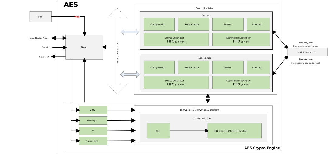
The AES engine uses DMA to move data between memory and fifo, and encrypts/decrypts data during the transfer process. DMA mode has high encryption/decryption efficiency for large amounts of data. However, DMA mode requires that the address and length of the data are aligned to the cache line length (32 bytes), otherwise there will be cache line data mismatch issues. If the address and length are not aligned, the serial port log will print a warning message. The driver has already handled the cache clean operation for the source address and cache invalidate operation for the destination address, so users do not need to clean the cache again outside the API.
DMA Mode
The AES engine uses DMA to move data between memory and fifo, and encrypts/decrypts data during the transfer process. DMA mode has high encryption/decryption efficiency for large amounts of data. However, DMA mode requires that the address and length of the data are aligned to the cache line length (32 bytes), otherwise there will be cache line data mismatch issues. If the address and length are not aligned, the serial port log will print a warning message. The driver has already handled the cache clean operation for the source address and cache invalidate operation for the destination address, so users do not need to clean the cache again outside the API.
DMA Mode
The AES engine uses DMA to move data between memory and fifo, and encrypts/decrypts data during the transfer process. DMA mode has high encryption/decryption efficiency for large amounts of data. However, DMA mode requires that the address and length of the data are aligned to the cache line length (32 bytes), otherwise there will be cache line data mismatch issues. If the address and length are not aligned, the serial port log will print a warning message. The driver has already handled the cache clean operation for the source address and cache invalidate operation for the destination address, so users do not need to clean the cache again outside the API.
DMA Mode
The AES engine uses DMA to move data between memory and fifo, and encrypts/decrypts data during the transfer process. DMA mode has high encryption/decryption efficiency for large amounts of data. However, DMA mode requires that the address and length of the data are aligned to the cache line length (32 bytes), otherwise there will be cache line data mismatch issues. If the address and length are not aligned, the serial port log will print a warning message. The driver has already handled the cache clean operation for the source address and cache invalidate operation for the destination address, so users do not need to clean the cache again outside the API.
DMA Mode
The AES engine uses DMA to move data between memory and fifo, and encrypts/decrypts data during the transfer process. DMA mode has high encryption/decryption efficiency for large amounts of data. However, DMA mode requires that the address and length of the data are aligned to the cache line length (32 bytes), otherwise there will be cache line data mismatch issues. If the address and length are not aligned, the serial port log will print a warning message. The driver has already handled the cache clean operation for the source address and cache invalidate operation for the destination address, so users do not need to clean the cache again outside the API.
DMA Mode
The AES engine uses DMA to move data between memory and fifo, and encrypts/decrypts data during the transfer process. DMA mode has high encryption/decryption efficiency for large amounts of data. However, DMA mode requires that the address and length of the data are aligned to the cache line length (32 bytes), otherwise there will be cache line data mismatch issues. If the address and length are not aligned, the serial port log will print a warning message. The driver has already handled the cache clean operation for the source address and cache invalidate operation for the destination address, so users do not need to clean the cache again outside the API.
AES engine supports two operation modes: DMA mode and Slave mode. Both modes can use Software key or OTP key.
DMA Mode
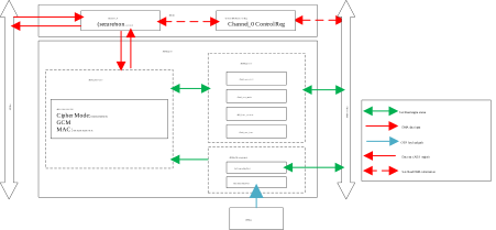
The AES engine uses channel 0 of the engine’s internal DMA controller. It uses DMA to move data between memory locations and encrypts/decrypts data during the transfer process. DMA mode has high encryption/decryption efficiency for large amounts of data. However, DMA mode requires that the address and length of the data are aligned to the cache line length (32 bytes), otherwise there will be cache line data mismatch issues. If the address and length are not aligned, the serial port log will print a warning message. The driver has already handled the cache clean operation for the source address and cache invalidate operation for the destination address, so users do not need to clean the cache again outside the API.
Slave Mode
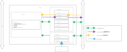
The CPU writes data to the AES engine through the APB bus to encrypt or decrypt data. This mode is suitable for 16-byte AES operations and has no restrictions on address or message length alignment. It can be used in combination with other modes to support more encryption or message authentication code algorithms.
The AES engine supports two operation modes: DMA mode and Slave mode. Both modes can use a Software key or an OTP key.
DMA Mode
In DMA mode, the AES engine uses channel 0 of the internal DMA controller to move data between memory locations and performs encryption or decryption during the transfer.
This mode is suitable for encrypting/decrypting large amounts of data and offers high operation efficiency. However, note the following constraints:
The data address and length must be aligned to 32 bytes (the cache line length), otherwise cache incoherence may occur.
The driver already handles cache clean and cache invalidate operations, so users do not need to handle them separately.
If the address or length is not aligned, the system prints a warning message to the serial port.
Slave Mode
In Slave mode, the CPU writes data into the AES engine’s internal FIFO through the APB bus, and the engine returns the result after the operation completes.
This mode is suitable for small AES operations (around 16 bytes) and has the following characteristics:
No address or message length alignment restrictions, providing flexible usage.
Can be combined with other modes to implement more complex encryption or message authentication code algorithms.
Higher CPU involvement, suitable for scenarios with low performance requirements.
Mode Selection Guidelines
Large data encryption/decryption (e.g., file encryption): Prefer DMA mode and ensure data alignment for best performance.
Small data operations (e.g., key derivation): Slave mode can be used to simplify alignment handling.
Combined algorithms (e.g., AES-GCM, AES-CCM): Slave mode works with other modes to implement complex encryption flows.
Note
SM4 uses the same operation modes as AES.
AES engine supports two operation modes: DMA mode and Slave mode. Both modes can use Software key or OTP key.
DMA Mode
The AES engine uses channel 0 of the engine’s internal DMA controller. It uses DMA to move data between memory locations and encrypts/decrypts data during the transfer process. DMA mode has high encryption/decryption efficiency for large amounts of data. However, DMA mode requires that the address and length of the data are aligned to the cache line length (32 bytes), otherwise there will be cache line data mismatch issues. If the address and length are not aligned, the serial port log will print a warning message. The driver has already handled the cache clean operation for the source address and cache invalidate operation for the destination address, so users do not need to clean the cache again outside the API.
Slave Mode
The CPU writes data to the AES engine through the APB bus to encrypt or decrypt data. This mode is suitable for 16-byte AES operations and has no restrictions on address or message length alignment. It can be used in combination with other modes to support more encryption or message authentication code algorithms.
AES API
Realtek provides ROM APIs, eliminating the need for users to manage specific register operations and processes. For enhanced applicability, the AES hardware acceleration engine has been integrated into MbedTLS. Due to hardware/software limitations, Realtek has not implemented hardware acceleration for MbedTLS’s CMAC/AES-GCM algorithms. Users can directly invoke ROM APIs during CMAC/AES-GCM operations for superior performance. Note that MbedTLS APIs only support software keys; ROM APIs must be used when employing OTP keys.
HMAC Engine
The HMAC engine is a hardware accelerator for computing HMAC and SHA2, supporting automatic message padding. The HMAC algorithm supports both software register keys and hardware OTP keys.
HMAC Algorithm Support
Supported key sizes: AES-128, AES-192, AES-256
Supported encryption/decryption modes:
ECB (Electronic Codebook)
CBC (Cipher Block Chaining)
OFB (Output Feedback)
CFB (Cipher Feedback)
CTR (Counter)
GCM (Galois/Counter)
Supported key sizes: AES-128, AES-192, AES-256
Supported encryption/decryption modes:
ECB (Electronic Codebook)
CBC (Cipher Block Chaining)
OFB (Output Feedback)
CFB (Cipher Feedback)
CTR (Counter)
GCM (Galois/Counter)
Supported key sizes: AES-128, AES-192, AES-256
Supported encryption/decryption modes:
ECB (Electronic Codebook)
CBC (Cipher Block Chaining)
OFB (Output Feedback)
CFB (Cipher Feedback)
CTR (Counter)
GCM (Galois/Counter)
Supported key sizes: AES-128, AES-192, AES-256
Supported encryption/decryption modes:
ECB (Electronic Codebook)
CBC (Cipher Block Chaining)
OFB (Output Feedback)
CFB (Cipher Feedback)
CTR (Counter)
GCM (Galois/Counter)
Supported key sizes: AES-128, AES-192, AES-256
Supported encryption/decryption modes:
ECB (Electronic Codebook)
CBC (Cipher Block Chaining)
OFB (Output Feedback)
CFB (Cipher Feedback)
CTR (Counter)
GCM (Galois/Counter)
Supported key sizes: AES-128, AES-192, AES-256
Supported encryption/decryption modes:
ECB (Electronic Codebook)
CBC (Cipher Block Chaining)
OFB (Output Feedback)
CFB (Cipher Feedback)
CTR (Counter)
GCM (Galois/Counter)
General Hash Functions
SHA2-224
SHA2-256
SHA2-384
SHA2-512
HMAC (Hash-based Message Authentication Code)
HMAC-SHA2-224
HMAC-SHA2-256
HMAC-SHA2-384
HMAC-SHA2-512
General Hash Functions
SHA2-224
SHA2-256
SHA2-384
SHA2-512
SM3 (256-bit digest)
HMAC (Hash-based Message Authentication Code)
HMAC-SHA2-224
HMAC-SHA2-256
HMAC-SHA2-384
HMAC-SHA2-512
HMAC-SM3
Note
SM3 and SHA2 use the same hardware engine; the algorithm core is selected via the SM3_MODE bit. SM3 uses a 64-byte block size, the same as SHA-256.
General Hash Functions
SHA2-224
SHA2-256
SHA2-384
SHA2-512
HMAC (Hash-based Message Authentication Code)
HMAC-SHA2-224
HMAC-SHA2-256
HMAC-SHA2-384
HMAC-SHA2-512
HMAC Keys
The HMAC engine features an independent key management unit supporting both software keys and hardware OTP keys.
The hardware encryption engine provides two key loading methods:
Software transfer: Keys are dynamically passed in by the application (software accessible)
OTP automatic loading: Keys are pre-burned into the OTP physical storage area (not accessible by software, only accessible by the encryption engine, preventing tampering or reading)
The OTP physical storage area supports storing 6 sets of keys, which need to be burned through the efuse command.
Engine Type |
Security |
Key Index |
OTP Key |
|---|---|---|---|
SHA HMAC |
Secure |
0 |
S_IPSEC_Key1 |
SHA HMAC |
Secure |
1 |
S_IPSEC_Key2 |
SHA HMAC |
Non-secure |
0 |
NS_IPSEC_Key1 |
SHA HMAC |
Non-secure |
1 |
NS_IPSEC_Key2 |
The detailed functions of OTP keys are shown below:
OTP Key Name |
Address |
Size bits |
Default Value |
Description |
|---|---|---|---|---|
S_IPSEC_Key1 (RDP) |
Logical map 0x200 |
256 |
0xFF |
When OTPKey_init function is enabled, the secure encryption engine will automatically load this key for HMAC or AES algorithm |
S_IPSEC_Key2 (Secure boot HMAC) |
Logical map 0x220 |
256 |
0xFF |
|
NS_IPSEC_Key1 |
Logical map 0x240 |
256 |
0xFF |
When OTPKey_init function is enabled, the non-secure encryption engine will automatically load this key for HMAC algorithm |
NS_IPSEC_Key2 |
Logical map 0x260 |
256 |
0xFF |
|
S_IPSEC_Key1_Read_Protection |
Physical map 0x365[3] |
1 |
1 |
0: Enable S_IPSEC_Key1 read protection, prohibit key from being read 1: Disable S_IPSEC_Key1 read protection |
S_IPSEC_Key1_Write_Protection |
Physical map 0x365[4] |
1 |
1 |
0: Enable S_IPSEC_Key1 write protection, prohibit key from being written to all 0s by hackers 1: Disable S_IPSEC_Key1 write protection |
S_IPSEC_Key2_Read_Protection |
Physical map 0x365[5] |
1 |
1 |
0: Enable S_IPSEC_Key2 read protection, prohibit key from being read 1: Disable S_IPSEC_Key2 read protection |
S_IPSEC_Key2_Write_Protection |
Physical map 0x365[6] |
1 |
1 |
0: Enable S_IPSEC_Key2 write protection, prohibit key from being written to all 0s by hackers 1: Disable S_IPSEC_Key2 write protection |
NS_IPSEC_Key1_Read_Protection |
Physical map 0x365[7] |
1 |
1 |
0: Enable NS_IPSEC_Key1 read protection, prohibit key from being read 1: Disable NS_IPSEC_Key1 read protection |
NS_IPSEC_Key1_Write_Protection |
Physical map 0x366[0] |
1 |
1 |
0: Enable NS_IPSEC_Key1 write protection, prohibit key from being written to all 0s by hackers 1: Disable NS_IPSEC_Key1 write protection |
NS_IPSEC_Key2_Read_Protection |
Physical map 0x366[1] |
1 |
1 |
0: Enable NS_IPSEC_Key2 read protection, prohibit key from being read 1: Disable NS_IPSEC_Key2 read protection |
NS_IPSEC_Key2_Write_Protection |
Physical map 0x366[2] |
1 |
1 |
0: Enable NS_IPSEC_Key2 write protection, prohibit key from being written to all 0s by hackers 1: Disable NS_IPSEC_Key2 write protection |
The hardware encryption engine provides two key loading methods:
Software transfer: Keys are dynamically passed in by the application (software accessible)
OTP automatic loading: Keys are pre-burned into the OTP physical storage area (not accessible by software, only accessible by the encryption engine, preventing tampering or reading)
The OTP physical storage area supports storing 6 sets of keys, which need to be burned through the efuse command.
Engine Type |
Security |
Key Index |
OTP Key |
|---|---|---|---|
SHA HMAC |
Secure |
0 |
S_IPSEC_Key1 |
SHA HMAC |
Secure |
1 |
S_IPSEC_Key2 |
SHA HMAC |
Non-secure |
0 |
NS_IPSEC_Key1 |
SHA HMAC |
Non-secure |
1 |
NS_IPSEC_Key2 |
The detailed functions of OTP keys are shown below:
OTP Key Name |
Address |
Size bits |
Default Value |
Description |
|---|---|---|---|---|
S_IPSEC_Key1 (RDP) |
Logical map 0x200 |
256 |
0xFF |
When OTPKey_init function is enabled, the secure encryption engine will automatically load this key for HMAC or AES algorithm |
S_IPSEC_Key2 (Secure boot HMAC) |
Logical map 0x220 |
256 |
0xFF |
|
NS_IPSEC_Key1 |
Logical map 0x240 |
256 |
0xFF |
When OTPKey_init function is enabled, the non-secure encryption engine will automatically load this key for HMAC algorithm |
NS_IPSEC_Key2 |
Logical map 0x260 |
256 |
0xFF |
|
S_IPSEC_Key1_Read_Protection |
Physical map 0x365[3] |
1 |
1 |
0: Enable S_IPSEC_Key1 read protection, prohibit key from being read 1: Disable S_IPSEC_Key1 read protection |
S_IPSEC_Key1_Write_Protection |
Physical map 0x365[4] |
1 |
1 |
0: Enable S_IPSEC_Key1 write protection, prohibit key from being written to all 0s by hackers 1: Disable S_IPSEC_Key1 write protection |
S_IPSEC_Key2_Read_Protection |
Physical map 0x365[5] |
1 |
1 |
0: Enable S_IPSEC_Key2 read protection, prohibit key from being read 1: Disable S_IPSEC_Key2 read protection |
S_IPSEC_Key2_Write_Protection |
Physical map 0x365[6] |
1 |
1 |
0: Enable S_IPSEC_Key2 write protection, prohibit key from being written to all 0s by hackers 1: Disable S_IPSEC_Key2 write protection |
NS_IPSEC_Key1_Read_Protection |
Physical map 0x365[7] |
1 |
1 |
0: Enable NS_IPSEC_Key1 read protection, prohibit key from being read 1: Disable NS_IPSEC_Key1 read protection |
NS_IPSEC_Key1_Write_Protection |
Physical map 0x366[0] |
1 |
1 |
0: Enable NS_IPSEC_Key1 write protection, prohibit key from being written to all 0s by hackers 1: Disable NS_IPSEC_Key1 write protection |
NS_IPSEC_Key2_Read_Protection |
Physical map 0x366[1] |
1 |
1 |
0: Enable NS_IPSEC_Key2 read protection, prohibit key from being read 1: Disable NS_IPSEC_Key2 read protection |
NS_IPSEC_Key2_Write_Protection |
Physical map 0x366[2] |
1 |
1 |
0: Enable NS_IPSEC_Key2 write protection, prohibit key from being written to all 0s by hackers 1: Disable NS_IPSEC_Key2 write protection |
The hardware encryption engine provides two key loading methods:
Software transfer: Keys are dynamically passed in by the application (software accessible)
OTP automatic loading: Keys are pre-burned into the OTP physical storage area (not accessible by software, only accessible by the encryption engine, preventing tampering or reading)
The OTP physical storage area supports storing 6 sets of keys, which need to be burned through the efuse command.
Engine Type |
Security |
Key Index |
OTP Key |
|---|---|---|---|
SHA HMAC |
Secure |
0 |
S_IPSEC_Key1 |
SHA HMAC |
Secure |
1 |
S_IPSEC_Key2 |
SHA HMAC |
Non-secure |
0 |
NS_IPSEC_Key1 |
SHA HMAC |
Non-secure |
1 |
NS_IPSEC_Key2 |
The detailed functions of OTP keys are shown below:
OTP Key Name |
Address |
Size bits |
Default Value |
Description |
|---|---|---|---|---|
S_IPSEC_Key1 (RDP) |
Logical map 0x200 |
256 |
0xFF |
When OTPKey_init function is enabled, the secure encryption engine will automatically load this key for HMAC or AES algorithm |
S_IPSEC_Key2 (Secure boot HMAC) |
Logical map 0x220 |
256 |
0xFF |
|
NS_IPSEC_Key1 |
Logical map 0x240 |
256 |
0xFF |
When OTPKey_init function is enabled, the non-secure encryption engine will automatically load this key for HMAC algorithm |
NS_IPSEC_Key2 |
Logical map 0x260 |
256 |
0xFF |
|
S_IPSEC_Key1_Read_Protection |
Physical map 0x365[3] |
1 |
1 |
0: Enable S_IPSEC_Key1 read protection, prohibit key from being read 1: Disable S_IPSEC_Key1 read protection |
S_IPSEC_Key1_Write_Protection |
Physical map 0x365[4] |
1 |
1 |
0: Enable S_IPSEC_Key1 write protection, prohibit key from being written to all 0s by hackers 1: Disable S_IPSEC_Key1 write protection |
S_IPSEC_Key2_Read_Protection |
Physical map 0x365[5] |
1 |
1 |
0: Enable S_IPSEC_Key2 read protection, prohibit key from being read 1: Disable S_IPSEC_Key2 read protection |
S_IPSEC_Key2_Write_Protection |
Physical map 0x365[6] |
1 |
1 |
0: Enable S_IPSEC_Key2 write protection, prohibit key from being written to all 0s by hackers 1: Disable S_IPSEC_Key2 write protection |
NS_IPSEC_Key1_Read_Protection |
Physical map 0x365[7] |
1 |
1 |
0: Enable NS_IPSEC_Key1 read protection, prohibit key from being read 1: Disable NS_IPSEC_Key1 read protection |
NS_IPSEC_Key1_Write_Protection |
Physical map 0x366[0] |
1 |
1 |
0: Enable NS_IPSEC_Key1 write protection, prohibit key from being written to all 0s by hackers 1: Disable NS_IPSEC_Key1 write protection |
NS_IPSEC_Key2_Read_Protection |
Physical map 0x366[1] |
1 |
1 |
0: Enable NS_IPSEC_Key2 read protection, prohibit key from being read 1: Disable NS_IPSEC_Key2 read protection |
NS_IPSEC_Key2_Write_Protection |
Physical map 0x366[2] |
1 |
1 |
0: Enable NS_IPSEC_Key2 write protection, prohibit key from being written to all 0s by hackers 1: Disable NS_IPSEC_Key2 write protection |
The hardware encryption engine provides two key loading methods:
Software transfer: Keys are dynamically passed in by the application (software accessible)
OTP automatic loading: Keys are pre-burned into the OTP physical storage area (not accessible by software, only accessible by the encryption engine, preventing tampering or reading)
The OTP physical storage area supports storing 6 sets of keys, which need to be burned through the efuse command.
Engine Type |
Security |
Key Index |
OTP Key |
|---|---|---|---|
SHA HMAC |
Secure |
0 |
S_IPSEC_Key1 |
SHA HMAC |
Secure |
1 |
S_IPSEC_Key2 |
SHA HMAC |
Non-secure |
0 |
NS_IPSEC_Key1 |
SHA HMAC |
Non-secure |
1 |
NS_IPSEC_Key2 |
The detailed functions of OTP keys are shown below:
OTP Key Name |
Address |
Size bits |
Default Value |
Description |
|---|---|---|---|---|
S_IPSEC_Key1 (RDP) |
Logical map 0x200 |
256 |
0xFF |
When OTPKey_init function is enabled, the secure encryption engine will automatically load this key for HMAC or AES algorithm |
S_IPSEC_Key2 (Secure boot HMAC) |
Logical map 0x220 |
256 |
0xFF |
|
NS_IPSEC_Key1 |
Logical map 0x240 |
256 |
0xFF |
When OTPKey_init function is enabled, the non-secure encryption engine will automatically load this key for HMAC algorithm |
NS_IPSEC_Key2 |
Logical map 0x260 |
256 |
0xFF |
|
S_IPSEC_Key1_Read_Protection |
Physical map 0x365[3] |
1 |
1 |
0: Enable S_IPSEC_Key1 read protection, prohibit key from being read 1: Disable S_IPSEC_Key1 read protection |
S_IPSEC_Key1_Write_Protection |
Physical map 0x365[4] |
1 |
1 |
0: Enable S_IPSEC_Key1 write protection, prohibit key from being written to all 0s by hackers 1: Disable S_IPSEC_Key1 write protection |
S_IPSEC_Key2_Read_Protection |
Physical map 0x365[5] |
1 |
1 |
0: Enable S_IPSEC_Key2 read protection, prohibit key from being read 1: Disable S_IPSEC_Key2 read protection |
S_IPSEC_Key2_Write_Protection |
Physical map 0x365[6] |
1 |
1 |
0: Enable S_IPSEC_Key2 write protection, prohibit key from being written to all 0s by hackers 1: Disable S_IPSEC_Key2 write protection |
NS_IPSEC_Key1_Read_Protection |
Physical map 0x365[7] |
1 |
1 |
0: Enable NS_IPSEC_Key1 read protection, prohibit key from being read 1: Disable NS_IPSEC_Key1 read protection |
NS_IPSEC_Key1_Write_Protection |
Physical map 0x366[0] |
1 |
1 |
0: Enable NS_IPSEC_Key1 write protection, prohibit key from being written to all 0s by hackers 1: Disable NS_IPSEC_Key1 write protection |
NS_IPSEC_Key2_Read_Protection |
Physical map 0x366[1] |
1 |
1 |
0: Enable NS_IPSEC_Key2 read protection, prohibit key from being read 1: Disable NS_IPSEC_Key2 read protection |
NS_IPSEC_Key2_Write_Protection |
Physical map 0x366[2] |
1 |
1 |
0: Enable NS_IPSEC_Key2 write protection, prohibit key from being written to all 0s by hackers 1: Disable NS_IPSEC_Key2 write protection |
The hardware encryption engine provides two key loading methods:
Software transfer: Keys are dynamically passed in by the application (software accessible)
OTP automatic loading: Keys are pre-burned into the OTP physical storage area (not accessible by software, only accessible by the encryption engine, preventing tampering or reading)
The OTP physical storage area supports storing 6 sets of keys, which need to be burned through the efuse command.
Engine Type |
Security |
Key Index |
OTP Key |
|---|---|---|---|
SHA HMAC |
Secure |
0 |
S_IPSEC_Key1 |
SHA HMAC |
Secure |
1 |
S_IPSEC_Key2 |
SHA HMAC |
Non-secure |
0 |
NS_IPSEC_Key1 |
SHA HMAC |
Non-secure |
1 |
NS_IPSEC_Key2 |
The detailed functions of OTP keys are shown below:
OTP Key Name |
Address |
Size bits |
Default Value |
Description |
|---|---|---|---|---|
S_IPSEC_Key1 (RDP) |
Logical map 0x200 |
256 |
0xFF |
When OTPKey_init function is enabled, the secure encryption engine will automatically load this key for HMAC or AES algorithm |
S_IPSEC_Key2 (Secure boot HMAC) |
Logical map 0x220 |
256 |
0xFF |
|
NS_IPSEC_Key1 |
Logical map 0x240 |
256 |
0xFF |
When OTPKey_init function is enabled, the non-secure encryption engine will automatically load this key for HMAC algorithm |
NS_IPSEC_Key2 |
Logical map 0x260 |
256 |
0xFF |
|
S_IPSEC_Key1_Read_Protection |
Physical map 0x365[3] |
1 |
1 |
0: Enable S_IPSEC_Key1 read protection, prohibit key from being read 1: Disable S_IPSEC_Key1 read protection |
S_IPSEC_Key1_Write_Protection |
Physical map 0x365[4] |
1 |
1 |
0: Enable S_IPSEC_Key1 write protection, prohibit key from being written to all 0s by hackers 1: Disable S_IPSEC_Key1 write protection |
S_IPSEC_Key2_Read_Protection |
Physical map 0x365[5] |
1 |
1 |
0: Enable S_IPSEC_Key2 read protection, prohibit key from being read 1: Disable S_IPSEC_Key2 read protection |
S_IPSEC_Key2_Write_Protection |
Physical map 0x365[6] |
1 |
1 |
0: Enable S_IPSEC_Key2 write protection, prohibit key from being written to all 0s by hackers 1: Disable S_IPSEC_Key2 write protection |
NS_IPSEC_Key1_Read_Protection |
Physical map 0x365[7] |
1 |
1 |
0: Enable NS_IPSEC_Key1 read protection, prohibit key from being read 1: Disable NS_IPSEC_Key1 read protection |
NS_IPSEC_Key1_Write_Protection |
Physical map 0x366[0] |
1 |
1 |
0: Enable NS_IPSEC_Key1 write protection, prohibit key from being written to all 0s by hackers 1: Disable NS_IPSEC_Key1 write protection |
NS_IPSEC_Key2_Read_Protection |
Physical map 0x366[1] |
1 |
1 |
0: Enable NS_IPSEC_Key2 read protection, prohibit key from being read 1: Disable NS_IPSEC_Key2 read protection |
NS_IPSEC_Key2_Write_Protection |
Physical map 0x366[2] |
1 |
1 |
0: Enable NS_IPSEC_Key2 write protection, prohibit key from being written to all 0s by hackers 1: Disable NS_IPSEC_Key2 write protection |
The hardware encryption engine provides two key loading methods:
Software transfer: Keys are dynamically passed in by the application (software accessible)
OTP automatic loading: Keys are pre-burned into the OTP physical storage area (not accessible by software, only accessible by the encryption engine, preventing tampering or reading)
The OTP physical storage area supports storing 6 sets of keys, which need to be burned through the efuse command.
Engine Type |
Security |
Key Index |
OTP Key |
|---|---|---|---|
SHA HMAC |
Secure |
0 |
S_IPSEC_Key1 |
SHA HMAC |
Secure |
1 |
S_IPSEC_Key2 |
SHA HMAC |
Non-secure |
0 |
NS_IPSEC_Key1 |
SHA HMAC |
Non-secure |
1 |
NS_IPSEC_Key2 |
The detailed functions of OTP keys are shown below:
OTP Key Name |
Address |
Size bits |
Default Value |
Description |
|---|---|---|---|---|
S_IPSEC_Key1 (RDP) |
Logical map 0x200 |
256 |
0xFF |
When OTPKey_init function is enabled, the secure encryption engine will automatically load this key for HMAC or AES algorithm |
S_IPSEC_Key2 (Secure boot HMAC) |
Logical map 0x220 |
256 |
0xFF |
|
NS_IPSEC_Key1 |
Logical map 0x240 |
256 |
0xFF |
When OTPKey_init function is enabled, the non-secure encryption engine will automatically load this key for HMAC algorithm |
NS_IPSEC_Key2 |
Logical map 0x260 |
256 |
0xFF |
|
S_IPSEC_Key1_Read_Protection |
Physical map 0x365[3] |
1 |
1 |
0: Enable S_IPSEC_Key1 read protection, prohibit key from being read 1: Disable S_IPSEC_Key1 read protection |
S_IPSEC_Key1_Write_Protection |
Physical map 0x365[4] |
1 |
1 |
0: Enable S_IPSEC_Key1 write protection, prohibit key from being written to all 0s by hackers 1: Disable S_IPSEC_Key1 write protection |
S_IPSEC_Key2_Read_Protection |
Physical map 0x365[5] |
1 |
1 |
0: Enable S_IPSEC_Key2 read protection, prohibit key from being read 1: Disable S_IPSEC_Key2 read protection |
S_IPSEC_Key2_Write_Protection |
Physical map 0x365[6] |
1 |
1 |
0: Enable S_IPSEC_Key2 write protection, prohibit key from being written to all 0s by hackers 1: Disable S_IPSEC_Key2 write protection |
NS_IPSEC_Key1_Read_Protection |
Physical map 0x365[7] |
1 |
1 |
0: Enable NS_IPSEC_Key1 read protection, prohibit key from being read 1: Disable NS_IPSEC_Key1 read protection |
NS_IPSEC_Key1_Write_Protection |
Physical map 0x366[0] |
1 |
1 |
0: Enable NS_IPSEC_Key1 write protection, prohibit key from being written to all 0s by hackers 1: Disable NS_IPSEC_Key1 write protection |
NS_IPSEC_Key2_Read_Protection |
Physical map 0x366[1] |
1 |
1 |
0: Enable NS_IPSEC_Key2 read protection, prohibit key from being read 1: Disable NS_IPSEC_Key2 read protection |
NS_IPSEC_Key2_Write_Protection |
Physical map 0x366[2] |
1 |
1 |
0: Enable NS_IPSEC_Key2 write protection, prohibit key from being written to all 0s by hackers 1: Disable NS_IPSEC_Key2 write protection |
The HMAC engine is equipped with an independent key management unit. The key management unit supports software keys and OTP hardware keys.
4 Secure OTP keys: After OTP keys are burned, read and write protection can be enabled. Once protection is enabled, software cannot read or write, only hardware can use them. By default, these OTP keys can only be used in Secure state. If a Secure OTP key needs to be used in Non-Secure state, the crypto_hmac_sha2_share_secure_key API must be called in secure state first to modify the key’s usage permissions.
1 Secure Software key: Register key can be freely configured through software. This Secure Software Key can only be read and written in secure state, Non-Secure state cannot access the key register. By default, the Secure Software key can only be used in Secure state. If the user needs to configure the key in Secure CPU and use the key in Non-Secure state, the corresponding key share register bit must be configured in secure state first.
1 Non-Secure Software key: Can be read, written, and used in both Secure and Non-Secure states.
HMAC Key ID |
Key Type |
Length (bits) |
OTP Address |
Key Usage Permission |
Shared IP |
|---|---|---|---|---|---|
0 |
OTP |
256 |
0x200 |
Secure (default) / Non-secure |
Shared with AES |
1 |
OTP |
256 |
0x220 |
Secure (default) / Non-secure |
Shared with AES |
2 |
OTP |
256 |
0x240 |
Secure (default) / Non-secure |
Shared with AES |
3 |
OTP |
256 |
0x260 |
Secure (default) / Non-secure |
Shared with AES |
33 |
Register |
256 |
N/A |
Secure (default) / Non-secure |
HMAC only |
34 |
Register |
256 |
N/A |
Non-secure |
HMAC only |
The HMAC engine provides three types of key resources:
Secure OTP Keys (ID 0~5): Keys are pre-programmed into the OTP region. After programming, read/write protection can be enabled. Once protection is enabled, software cannot read/write the keys; only hardware can use them. By default, these keys are only usable in Secure state. To use them in Non-Secure state, first call the
crypto_hmac_share_secure_keyAPI to modify the key’s usage permission.Secure Software Key (ID 33): A register key that can be freely configured by software. It can only be read/written in Secure state; Non-Secure state cannot access the key registers. To configure the key in Secure state and use it in Non-Secure state, first set the corresponding key share register bits.
Shared Software Key (ID 34): A register key that can be read, written, and used in either Secure or Non-Secure state.
Note
HMAC keys support 128, 192, and 256-bit lengths. SM3-HMAC uses the same key resources.
HMAC Key ID |
Key Type |
Length (bits) |
OTP Addr |
Key Usage Permission |
Shared IP |
|---|---|---|---|---|---|
0 |
OTP |
256 |
0x200 |
Secure (default) / Non-Secure |
Shared with AES |
1 |
OTP |
256 |
0x220 |
Secure (default) / Non-Secure |
Shared with AES |
2 |
OTP |
256 |
0x240 |
Secure (default) / Non-Secure |
Shared with AES |
3 |
OTP |
256 |
0x260 |
Secure (default) / Non-Secure |
Shared with AES |
4 |
OTP |
256 |
0x2C0 |
Secure (default) / Non-Secure |
Shared with RSIP |
5 |
OTP |
256 |
0x2E0 |
Secure (default) / Non-Secure |
Shared with RSIP |
33 |
Register |
256 |
N/A |
Secure (default) / Non-Secure |
Shared with AES |
34 |
Register |
256 |
N/A |
Secure / Non-Secure |
Shared with AES |
The HMAC engine is equipped with an independent key management unit. The key management unit supports software keys and OTP hardware keys.
6 Secure OTP keys: After OTP keys are burned, read and write protection can be enabled. Once protection is enabled, software cannot read or write, only hardware can use them. By default, these OTP keys can only be used in Secure state. If a Secure OTP key needs to be used in Non-Secure state, the crypto_hmac_sha2_share_secure_key API must be called in secure state first to modify the key’s usage permissions.
1 Secure Software key: Register key can be freely configured through software. This Secure Software Key can only be read and written in secure state, Non-Secure state cannot access the key register. By default, the Secure Software key can only be used in Secure state. If the user needs to configure the key in Secure CPU and use the key in Non-Secure state, the corresponding key share register bit must be configured in secure state first.
1 Non-Secure Software key: Can be read, written, and used in both Secure and Non-Secure states.
HMAC Key ID |
Key Type |
Length (bits) |
OTP Address |
Key Usage Permission |
Shared IP |
|---|---|---|---|---|---|
0 |
OTP |
256 |
0x280 |
Secure (default) / Non-secure |
Shared with AES |
1 |
OTP |
256 |
0x2A0 |
Secure (default) / Non-secure |
Shared with AES |
2 |
OTP |
256 |
0x2C0 |
Secure (default) / Non-secure |
Shared with AES |
3 |
OTP |
256 |
0x2E0 |
Secure (default) / Non-secure |
Shared with AES |
4 |
OTP |
256 |
0x300 |
Non-secure |
Shared with AES |
5 |
OTP |
256 |
0x320 |
Non-secure |
Shared with AES |
33 |
Register |
256 |
N/A |
Secure (default) / Non-secure |
HMAC only |
34 |
Register |
256 |
N/A |
Non-secure |
HMAC only |
HMAC Engine Security
The HASH architecture achieves efficient encryption processing while ensuring security through hardware-level isolation and intelligent arbitration:
Two independent register sets:
Secure address space: 0x5XXX_XXXX, mapped to secure-dedicated registers
Non-secure address space: 0x4XXX_XXXX, mapped to non-secure-dedicated registers
Arbitration mechanism when both secure and non-secure domains request the encryption engine simultaneously:
Basic policy: Round-robin scheduling + FIFO status priority (full FIFO has priority)
Atomicity guarantee: Must complete an entire round of encryption operation (LS=1) before switching engine control
Interrupt mechanism:
Physical isolation design: Secure and non-secure interrupts are connected to different interrupt numbers
Error isolation reporting: Bus errors trigger both interrupts simultaneously, but need to be cleared independently
Special setting: Interrupt security attributes only support automatic hardware switching
The HASH architecture achieves efficient encryption processing while ensuring security through hardware-level isolation and intelligent arbitration:
Two independent register sets:
Secure address space: 0x5XXX_XXXX, mapped to secure-dedicated registers
Non-secure address space: 0x4XXX_XXXX, mapped to non-secure-dedicated registers
Arbitration mechanism when both secure and non-secure domains request the encryption engine simultaneously:
Basic policy: Round-robin scheduling + FIFO status priority (full FIFO has priority)
Atomicity guarantee: Must complete an entire round of encryption operation (LS=1) before switching engine control
Interrupt mechanism:
Physical isolation design: Secure and non-secure interrupts are connected to different interrupt numbers
Error isolation reporting: Bus errors trigger both interrupts simultaneously, but need to be cleared independently
Special setting: Interrupt security attributes only support automatic hardware switching
The HASH architecture achieves efficient encryption processing while ensuring security through hardware-level isolation and intelligent arbitration:
Two independent register sets:
Secure address space: 0x5XXX_XXXX, mapped to secure-dedicated registers
Non-secure address space: 0x4XXX_XXXX, mapped to non-secure-dedicated registers
Arbitration mechanism when both secure and non-secure domains request the encryption engine simultaneously:
Basic policy: Round-robin scheduling + FIFO status priority (full FIFO has priority)
Atomicity guarantee: Must complete an entire round of encryption operation (LS=1) before switching engine control
Interrupt mechanism:
Physical isolation design: Secure and non-secure interrupts are connected to different interrupt numbers
Error isolation reporting: Bus errors trigger both interrupts simultaneously, but need to be cleared independently
Special setting: Interrupt security attributes only support automatic hardware switching
The HASH architecture achieves efficient encryption processing while ensuring security through hardware-level isolation and intelligent arbitration:
Two independent register sets:
Secure address space: 0x5XXX_XXXX, mapped to secure-dedicated registers
Non-secure address space: 0x4XXX_XXXX, mapped to non-secure-dedicated registers
Arbitration mechanism when both secure and non-secure domains request the encryption engine simultaneously:
Basic policy: Round-robin scheduling + FIFO status priority (full FIFO has priority)
Atomicity guarantee: Must complete an entire round of encryption operation (LS=1) before switching engine control
Interrupt mechanism:
Physical isolation design: Secure and non-secure interrupts are connected to different interrupt numbers
Error isolation reporting: Bus errors trigger both interrupts simultaneously, but need to be cleared independently
Special setting: Interrupt security attributes only support automatic hardware switching
The HASH architecture achieves efficient encryption processing while ensuring security through hardware-level isolation and intelligent arbitration:
Two independent register sets:
Secure address space: 0x5XXX_XXXX, mapped to secure-dedicated registers
Non-secure address space: 0x4XXX_XXXX, mapped to non-secure-dedicated registers
Arbitration mechanism when both secure and non-secure domains request the encryption engine simultaneously:
Basic policy: Round-robin scheduling + FIFO status priority (full FIFO has priority)
Atomicity guarantee: Must complete an entire round of encryption operation (LS=1) before switching engine control
Interrupt mechanism:
Physical isolation design: Secure and non-secure interrupts are connected to different interrupt numbers
Error isolation reporting: Bus errors trigger both interrupts simultaneously, but need to be cleared independently
Special setting: Interrupt security attributes only support automatic hardware switching
The HASH architecture achieves efficient encryption processing while ensuring security through hardware-level isolation and intelligent arbitration:
Two independent register sets:
Secure address space: 0x5XXX_XXXX, mapped to secure-dedicated registers
Non-secure address space: 0x4XXX_XXXX, mapped to non-secure-dedicated registers
Arbitration mechanism when both secure and non-secure domains request the encryption engine simultaneously:
Basic policy: Round-robin scheduling + FIFO status priority (full FIFO has priority)
Atomicity guarantee: Must complete an entire round of encryption operation (LS=1) before switching engine control
Interrupt mechanism:
Physical isolation design: Secure and non-secure interrupts are connected to different interrupt numbers
Error isolation reporting: Bus errors trigger both interrupts simultaneously, but need to be cleared independently
Special setting: Interrupt security attributes only support automatic hardware switching
The engine algorithm has passed NIST CAVP certification.
The HASH engine supports TrustZone technology and can automatically identify whether the CPU access is in Secure or Non-secure state. It incorporates a hardware mutex lock mechanism, meaning the CPU must first obtain this mutex lock before each operation; otherwise, it cannot access the hardware registers.
When the Secure CPU holds the lock, all Non-secure access is blocked. Only after the Secure CPU releases the lock can the Non-secure CPU regain access. Conversely, if a Non-secure CPU holds the lock, the Secure CPU can configure a dedicated preemption register to forcibly release the Non-secure lock and reset the engine, thereby immediately gaining control of the engine.
Additionally, each time the lock is released, the engine automatically clears sensitive information from the hardware and register states, ensuring no information leakage occurs.
The HMAC engine supports TrustZone technology and can automatically identify whether a CPU access is in Secure or Non-secure state.
Hardware Mutex Lock Mechanism
The engine incorporates a built-in hardware mutex lock. The CPU must obtain the lock before each operation; otherwise, it cannot access the hardware registers.
When the Secure CPU holds the lock, all Non-secure access is blocked.
When the Non-secure CPU holds the lock, the Secure CPU can forcibly release the Non-secure lock and reset the engine through a dedicated preemption register, thereby immediately gaining control.
Each time the lock is released, the engine automatically clears sensitive information from the hardware and register states to prevent information leakage.
Note
SM3 uses the same security mechanism as SHA2.
The engine algorithm has passed NIST CAVP certification.
The HASH engine supports TrustZone technology and can automatically identify whether the CPU access is in Secure or Non-secure state. It incorporates a hardware mutex lock mechanism, meaning the CPU must first obtain this mutex lock before each operation; otherwise, it cannot access the hardware registers.
When the Secure CPU holds the lock, all Non-secure access is blocked. Only after the Secure CPU releases the lock can the Non-secure CPU regain access. Conversely, if a Non-secure CPU holds the lock, the Secure CPU can configure a dedicated preemption register to forcibly release the Non-secure lock and reset the engine, thereby immediately gaining control of the engine.
Additionally, each time the lock is released, the engine automatically clears sensitive information from the hardware and register states, ensuring no information leakage occurs.
HMAC Engine Usage Modes
DMA Mode
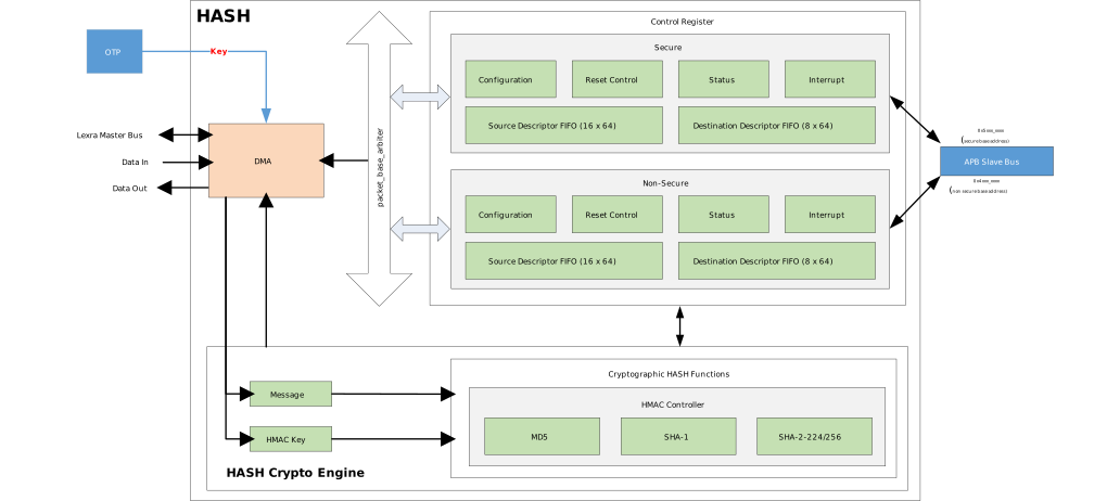
The HASH engine uses DMA to move data between memory and fifo, and uses HMAC to encrypt/decrypt data during the transfer process. DMA mode has high encryption/decryption efficiency for large amounts of data. However, DMA mode requires that the address and length of the data are aligned to the cache line length (32 bytes), otherwise there will be cache line data mismatch issues. If the address and length are not aligned, the serial port log will print a warning message. The driver has already handled the cache clean operation for the source address and cache invalidate operation for the destination address, so users do not need to clean the cache again outside the API.
DMA Mode
The HASH engine uses DMA to move data between memory and fifo, and uses HMAC to encrypt/decrypt data during the transfer process. DMA mode has high encryption/decryption efficiency for large amounts of data. However, DMA mode requires that the address and length of the data are aligned to the cache line length (32 bytes), otherwise there will be cache line data mismatch issues. If the address and length are not aligned, the serial port log will print a warning message. The driver has already handled the cache clean operation for the source address and cache invalidate operation for the destination address, so users do not need to clean the cache again outside the API.
DMA Mode
The HASH engine uses DMA to move data between memory and fifo, and uses HMAC to encrypt/decrypt data during the transfer process. DMA mode has high encryption/decryption efficiency for large amounts of data. However, DMA mode requires that the address and length of the data are aligned to the cache line length (32 bytes), otherwise there will be cache line data mismatch issues. If the address and length are not aligned, the serial port log will print a warning message. The driver has already handled the cache clean operation for the source address and cache invalidate operation for the destination address, so users do not need to clean the cache again outside the API.
DMA Mode
The HASH engine uses DMA to move data between memory and fifo, and uses HMAC to encrypt/decrypt data during the transfer process. DMA mode has high encryption/decryption efficiency for large amounts of data. However, DMA mode requires that the address and length of the data are aligned to the cache line length (32 bytes), otherwise there will be cache line data mismatch issues. If the address and length are not aligned, the serial port log will print a warning message. The driver has already handled the cache clean operation for the source address and cache invalidate operation for the destination address, so users do not need to clean the cache again outside the API.
DMA Mode
The HASH engine uses DMA to move data between memory and fifo, and uses HMAC to encrypt/decrypt data during the transfer process. DMA mode has high encryption/decryption efficiency for large amounts of data. However, DMA mode requires that the address and length of the data are aligned to the cache line length (32 bytes), otherwise there will be cache line data mismatch issues. If the address and length are not aligned, the serial port log will print a warning message. The driver has already handled the cache clean operation for the source address and cache invalidate operation for the destination address, so users do not need to clean the cache again outside the API.
DMA Mode
The HASH engine uses DMA to move data between memory and fifo, and uses HMAC to encrypt/decrypt data during the transfer process. DMA mode has high encryption/decryption efficiency for large amounts of data. However, DMA mode requires that the address and length of the data are aligned to the cache line length (32 bytes), otherwise there will be cache line data mismatch issues. If the address and length are not aligned, the serial port log will print a warning message. The driver has already handled the cache clean operation for the source address and cache invalidate operation for the destination address, so users do not need to clean the cache again outside the API.
HMAC engine supports two operation modes: DMA mode and Slave mode. Both modes can use Software key or OTP key.
DMA Mode
The HMAC engine shares a DMA controller with AES. The HMAC engine can only use channel 1 of the DMA.
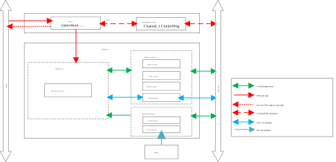
In DMA mode, the engine supports read-only mode and copy mode:
Read-only mode: At startup, only the source data address needs to be specified. The engine will only read data from the data address and calculate the hash.
Copy mode: At startup, both the source data address and destination address need to be specified. While calculating the hash, the engine will also transfer the data completely to the destination address. This is suitable for copy verification scenarios.
Slave Mode
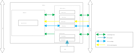
The CPU writes the message to the internal FIFO of the engine through the APB bus, then reads out the hash value. Customers do not need to be concerned with this mode.
The HMAC engine supports two operation modes: DMA mode and Slave mode. Both modes can use a Software key or an OTP key.
DMA Mode
The HMAC engine shares the same DMA controller as the AES engine but uses a separate channel 1.
In DMA mode, the HMAC engine supports read-only mode and copy mode:
Read-only mode: Only the source data address is specified at startup. The engine reads data from that address and computes the hash value, suitable for data integrity verification scenarios.
Copy mode: Both the source and destination addresses are specified at startup. The engine computes the hash while moving the data to the destination address, suitable for copy-and-verify scenarios.
Slave Mode
In Slave mode, the CPU writes the message into the engine’s internal FIFO through the APB bus, then reads out the hash value.
This mode is used internally by the low-level driver; users do not need to be concerned with the implementation details.
Note
SM3 uses the same operation modes as SHA2.
HMAC engine supports two operation modes: DMA mode and Slave mode. Both modes can use Software key or OTP key.
DMA Mode
The HMAC engine shares a DMA controller with AES. The HMAC engine can only use channel 1 of the DMA.
In DMA mode, the engine supports read-only mode and copy mode:
Read-only mode: At startup, only the source data address needs to be specified. The engine will only read data from the data address and calculate the hash.
Copy mode: At startup, both the source data address and destination address need to be specified. While calculating the hash, the engine will also transfer the data completely to the destination address. This is suitable for copy verification scenarios.
Slave Mode
The CPU writes the message to the internal FIFO of the engine through the APB bus, then reads out the hash value. Customers do not need to be concerned with this mode.
HMAC API
Realtek provides low-level HMAC APIs, freeing users from managing specific register operations and processes. For broader applicability, the SHA2 hardware acceleration engine has been integrated into MbedTLS SHA2-Hash/HMAC APIs. Other hash algorithms (e.g., SHA1/MD5) lack hardware acceleration. MbedTLS APIs only support software keys and require low-level APIs for OTP key usage. Additionally, MbedTLS APIs do not support DMA copy mode.
Crypto Key Byte Order
The Crypto Engine key byte order is consistent with MbedTLS data structures, both adopting little-endian byte order. The following example uses a 256-bit key to illustrate the correct byte order for converting from a readable hexadecimal string to an array and programming it into OTP.
Example Key
Original key (hexadecimal large number representation):
0x0123456789abcdef0123456789abcdef00112233445566778899aabbccddeeff
Key Array Definition
When passing the key as a byte array to the hardware API in a program, it must be arranged in little-endian order. Example array for 32 bytes:
/* 256-bit key, little-endian byte order */
uint8_t key1[32] = {
   0xff, 0xee, 0xdd, 0xcc, 0xbb, 0xaa, 0x99, 0x88, 0x77, 0x66, 0x55, 0x44, 0x33, 0x22, 0x11, 0x00,
   0xef, 0xcd, 0xab, 0x89, 0x67, 0x45, 0x23, 0x01, 0xef, 0xcd, 0xab, 0x89, 0x67, 0x45, 0x23, 0x01
};
OTP Key Programming Flow
The following example uses NS_IPSEC_Key2: First generate a little-endian ordered key, then use the AT+OTP=WRAW serial programming command to write to OTP physical address 0x260 (length 0x20, 32 bytes):
AT+OTP=WRAW,0x260,0x20,ffeeddccbbaa99887766554433221100efcdab8967452301efcdab8967452301
In mass production, after the key is written, key read protection and write protection must be enabled according to the OTP table descriptions to prevent OTP keys from being tampered with or leaked.
Note
The above example uses a 32-byte NS_IPSEC_Key2 key; actual address and length should be adjusted according to actual needs.
Note that after OTP programming and system reset, the OTP key can be loaded into the engine.
This byte order rule applies to all IC models.
OTP Key Content Mapping
The actual content in the OTP physical address section after writing the above command:
Address |
b0 |
b1 |
b2 |
b3 |
b4 |
b5 |
b6 |
b7 |
b8 |
b9 |
b10 |
b11 |
b12 |
b13 |
b14 |
b15 |
|---|---|---|---|---|---|---|---|---|---|---|---|---|---|---|---|---|
0x260 |
ff |
ee |
dd |
cc |
bb |
aa |
99 |
88 |
77 |
66 |
55 |
44 |
33 |
22 |
11 |
00 |
0x270 |
ef |
cd |
ab |
89 |
67 |
45 |
23 |
01 |
ef |
cd |
ab |
89 |
67 |
45 |
23 |
01 |
Raw API
AES Exported Types
-
struct AES_InitTypeDef
AES Init Structure Definition.
Public Members
-
u32 CipherMode
Specifies the AES cipher mode. This parameter can be a value of AES Cipher Mode.
-
u32 EngineMode
Specifies the AES engine mode. This parameter can be a value of AES Engine Mode.
-
u32 IsEnc
Specifies AES encrypt or decrypt. This parameter can be TRUE or FALSE.
-
u32 CipherLen
Specifies the AES cipher length in bytes.
-
u32 key_len
AES key length in bits. This parameter can be a value of AES Key Size.
-
u32 CipherMode
SHA Exported Types
-
struct SHA_InitTypeDef
SHA Init Structure Definition.
Public Members
-
u32 EngineMode
Specifies the SHA engine mode. This parameter can be a value of SHA Engine Mode.
-
u32 IcgEn
Specifies enable or disable SHA auto clock gating. This parameter can be ENABLE or DISABLE.
-
u32 DmaMode
Specifies SHA DMA mode. This parameter can be a value of SHA DMA Mode.
-
u32 HmacMode
Specifies the HMAC mode. This parameter can be a value of SHA HMAC Mode.
-
u32 EngineMode
-
struct SHA_context
SHA Context Structure Definition.
Public Members
-
u32 hmac_mode
HMAC operation mode. 0x0: hash mode. 0x1: HMAC mode.
-
u32 block_size
Block size. This parameter can be a value of SHA Block Size.
-
u32 ilen_bytes
Bytes occupied by input length storage.
-
u32 digest_len
Digest length.
-
u32 state[16]
Digest state
-
u8 buffer[128]
Data block being processed
-
u32 buf_used_bytes
Buffer bytes used
-
u32 total_len
The total number of data bytes to be processed
-
u8 dma_copy
DMA operation mode. 0x0: read-only mode. 0x1: copy mode
-
u8 seq_hash_first
Flag for sequential hash: 1 = this is the first block, 0 = subsequent block
-
u8 key_id
Key management key ID used for HMAC
-
u32 key_len_bits
HMAC key length in bits
-
u32 DMA_CTL_LOW
DMA control register low word value cached for this context
-
u32 hmac_mode
Hash Engine Mode
Not supported.
-
enum hash_engine_mode
Hash engine selector for SHA-2 and SM3 algorithms.
Values:
/* Use SHA-2 engine (supports SHA-224/256/384/512) */
HASH_SHA2_MODE = 0

/* Use SM3 engine */
HASH_SM3_MODE = 1
Crypto Symmetric Cipher Exported Types
Crypto Engine Mode
Not supported.
-
enum crypto_engine_mode
Cipher engine selector for unified symmetric cipher APIs.
Values:
/* Use AES cipher engine */
CRYPTO_AES_MODE = 0

/* Use SM4 cipher engine */
CRYPTO_SM4_MODE = 1
AES Exported Constants
AES Byte Swap Defaults
/* Default byte swap: key in native order, no swap */
#define AES_BYTE_SWAP_DEFAULTS AES_BIT_KEY_SWAP_DISABLE

/* Byte swap setting: key swap disabled (both key and payload in native order) */
#define AES_BYTE_SWAP_KEY_SWAP ((u32) 0x00)
AES Cipher Mode
/* AES encryption direction */
#define CIPHER_ENCRYPTION_MODE ((u8)0x01)

/* AES decryption direction */
#define CIPHER_DECRYPTION_MODE ((u8)0x00)

/* Electronic Codebook mode */
#define CIPHER_MODE_ECB ((u8)0x00)

/* Cipher Block Chaining mode */
#define CIPHER_MODE_CBC ((u8)0x01)

/* Cipher Feedback mode */
#define CIPHER_MODE_CFB ((u8)0x02)

/* Output Feedback mode */
#define CIPHER_MODE_OFB ((u8)0x03)

/* Counter mode */
#define CIPHER_MODE_CTR ((u8)0x04)

/* Galois Message Authentication Code mode */
#define CIPHER_MODE_GMAC ((u8)0x05)

/* Galois/Counter Mode (authenticated encryption) */
#define CIPHER_MODE_GCM ((u8)0x06)

/* Cipher-based Message Authentication Code mode */
#define CIPHER_MODE_CMAC ((u8)0x07)
/* XEX-based tweaked-codebook mode with ciphertext stealing */
#define CIPHER_MODE_XTS ((u8)0x08)

/* Check whether MODE is a valid AES cipher mode. */
#define IS_AES_CIPHER_MODE (((MODE) == CIPHER_MODE_ECB) || \
    ((MODE) == CIPHER_MODE_CBC) || \
    ((MODE) == CIPHER_MODE_CFB) || \
    ((MODE) == CIPHER_MODE_OFB) || \
    ((MODE) == CIPHER_MODE_CTR) || \
    ((MODE) == CIPHER_MODE_GMAC) || \
    ((MODE) == CIPHER_MODE_GCM) || \
    ((MODE) == CIPHER_MODE_CMAC) || \
    ((MODE) == CIPHER_MODE_XTS))
/* CBC-MAC mode */
#define CIPHER_MODE_CBC_MAC ((u8)0x09)

/* Counter with CBC-MAC mode (authenticated encryption) */
#define CIPHER_MODE_CCM ((u8)0x0A)

/* Check whether MODE is a valid AES cipher mode. */
#define IS_AES_CIPHER_MODE (((MODE) == CIPHER_MODE_ECB) || \
    ((MODE) == CIPHER_MODE_CBC) || \
    ((MODE) == CIPHER_MODE_CFB) || \
    ((MODE) == CIPHER_MODE_OFB) || \
    ((MODE) == CIPHER_MODE_CTR) || \
    ((MODE) == CIPHER_MODE_GMAC) || \
    ((MODE) == CIPHER_MODE_GCM) || \
    ((MODE) == CIPHER_MODE_CMAC))
AES DMA Size
/* AES block size in bytes */
#define AES_BLOCK_SIZE 16

/* AES block size in bits */
#define AES_BLOCK_SIZE_BIT 128

/* Maximum DMA block transfer size in transfer units */
#define AES_DMA_MAX_BLOCK_TS 536870910

/* Maximum DMA transfer size in bytes */
#define AES_DMA_MAX_BLOCK_BYTE (AES_DMA_MAX_BLOCK_TS * 1)
AES DMA Settings
/* DMA channel number for AES transfers */
#define AES_DMA_CH_NUM 0

/* DMA channel enable mask bit for AES */
#define AES_DMA_CH_MASK ((u32)0x00000001 << AES_DMA_CH_NUM)
AES Engine Mode
/* Slave mode: plaintext written directly to hardware registers */
#define AES_SLAVE_MODE ((u8)0x00)

/* DMA mode: plaintext transferred via DMA */
#define AES_DMA_MODE ((u8)0x01)

/* Check whether MODE is a valid AES engine mode. */
#define IS_AES_ENGINE_MODE (((MODE) == AES_SLAVE_MODE) || \
    ((MODE) == AES_DMA_MODE))
AES Key Size
/* Key size 128 bits */
#define AES_KEY_SIZE_128 ((u8)0x00)

/* Key size 192 bits */
#define AES_KEY_SIZE_192 ((u8)0x01)

/* Key size 256 bits */
#define AES_KEY_SIZE_256 ((u8)0x02)
AES Timeout
/* DMA mode operation timeout count */
#define AES_DMA_TIMEOUT ((u32) 10000000)

/* Engine mutex acquisition timeout count */
#define AES_MUTEX_TIMEOUT ((u32) 1000000)

/* Slave mode operation timeout count */
#define AES_SLAVE_TIMEOUT ((u32) 10000)
Crypto Block Size
Not supported.
/* AES/cipher block size in bytes */
#define CIPHER_BLOCK_SIZE 16
HW_CRYPTO_ENGINE Exported Constants
Crypto Key
/* 128 bits */
#define KEY_BIT_128 (128)

/* 192 bits */
#define KEY_BIT_192 (192)

/* 256 bits */
#define KEY_BIT_256 (256)

/* Reverse the byte order of a 32-bit word (swap big-endian and little-endian). */
#define BIG_LITTLE_SWAP32 ( (((*(long int *)&x) & 0xff000000) >> 24) | \
    (((*(long int *)&x) & 0x00ff0000) >> 8) | \
    (((*(long int *)&x) & 0x0000ff00) << 8) | \
    (((*(long int *)&x) & 0x000000ff) << 24) )
/* Check whether LEN is a valid AES key length in bits. */
#define IS_KEY_LEN_BIT (((LEN) == KEY_BIT_128) || \
    ((LEN) == KEY_BIT_192) || \
    ((LEN) == KEY_BIT_256))
/* Check whether LEN is a valid AES key length in bits. */
#define CRYPTO_IS_KEY_LEN_BIT (((LEN) == KEY_BIT_128) || \
    ((LEN) == KEY_BIT_192) || \
    ((LEN) == KEY_BIT_256))
Crypto Process Status
/* Descriptor number out of valid range */
#define _ERRNO_CRYPTO_DESC_NUM_SET_OutRange -2

/* DMA burst number out of valid range */
#define _ERRNO_CRYPTO_BURST_NUM_SET_OutRange -3

/* NULL pointer passed as argument */
#define _ERRNO_CRYPTO_NULL_POINTER -4

/* Crypto engine not initialized */
#define _ERRNO_CRYPTO_ENGINE_NOT_INIT -5

/* Buffer address not 4-byte aligned */
#define _ERRNO_CRYPTO_ADDR_NOT_4Byte_Aligned -6

/* Key index out of valid range */
#define _ERRNO_CRYPTO_KEY_OutRange -7

/* Message length out of valid range */
#define _ERRNO_CRYPTO_MSG_OutRange -8

/* IV length out of valid range */
#define _ERRNO_CRYPTO_IV_OutRange -9

/* Authentication type mismatch */
#define _ERRNO_CRYPTO_AUTH_TYPE_NOT_MATCH -10

/* Cipher type mismatch */
#define _ERRNO_CRYPTO_CIPHER_TYPE_NOT_MATCH -11

/* Key and IV length mismatch */
#define _ERRNO_CRYPTO_KEY_IV_LEN_DIFF -12

/* hash_final called without prior hash_update */
#define _ERRNO_CRYPTO_HASH_FINAL_NO_UPDATE -13

/* Secure key access error */
#define _ERRNO_CRYPTO_KEY_SECURE_ERR -14

/* Invalid key length */
#define _ERRNO_CRYPTO_KEY_LENGTH_ERR -15

/* Key load failure */
#define _ERRNO_CRYPTO_KEY_LOAD_ERR -16

/* DMA transfer error */
#define _ERRNO_CRYPTO_DMA_ERR -17

/* Invalid message length */
#define _ERRNO_CRYPTO_MESSAGE_LEN_ERR -18

/* Tag length out of valid range */
#define _ERRNO_CRYPTO_TAG_OutRange -19

/* GCM authentication tag verification failed */
#define _ERRNO_CRYPTO_GCM_TAG_NOT_MATCH -20

/* Slave mode operation timeout */
#define _ERRNO_CRYPTO_SLAVE_TIME_OUT -21

/* Slave mode hardware error */
#define _ERRNO_CRYPTO_SLAVE_ERROR -22
Not supported.
/* AAD length out of valid range */
#define _ERRNO_CRYPTO_AAD_LENGTH_OutRange -23

/* DMA operation timeout */
#define _ERRNO_CRYPTO_DMA_TIMEOUT -24

/* Invalid cipher mode */
#define _ERRNO_CRYPTO_MODE_ERR -25

/* Output buffer too small */
#define _ERRNO_CRYPTO_BUFFER_TOO_SMALL -26

/* Authentication/tag verification failed */
#define _ERRNO_CRYPTO_AUTH_FAILED -27
SHA Exported Constants
Not supported.
/* Bitmask of SHA CONTROL register bits cleared when starting a new hash operation. */
#define HASH_INIT_MASK (SHA_BIT_SLAVE_MODE | SHA_BIT_DMA_MODE | SHA_BIT_HMAC_MODE | SHA_MASK_SHA2_MODE | SHA_BIT_SM3_MODE)
SHA Block Size
/* Block size in bytes for SHA-224/256 (512-bit block = 64 bytes) */
#define SHA_BLOCK_256 64

/* Block size in bytes for SHA-384/512 (1024-bit block = 128 bytes) */
#define SHA_BLOCK_512 128
SHA Byte Inversion
/* Native (big-endian) byte order */
#define SHA_NATIVE_ORDER ((u8)0x00)

/* Inverse (little-endian) byte order */
#define SHA_INVERSE_ORDER ((u8)0x01)

/* Check whether INV is a valid SHA byte inversion setting. */
#define IS_SHA_BYTE_INV (((INV) == SHA_NATIVE_ORDER) || \
    ((INV) == SHA_INVERSE_ORDER))
SHA Byte Swap Defaults
/* Bitmask for key and payload byte inversion bits in CONTROL register */
#define SHA_MASK_BYTE_INVERSION ((u32)0x00000003 << 12)
/* Default: key in native order, payload byte-inverted */
#define SHA_BYTE_SWAP_DEFAULTS ((u32)(~SHA_BIT_KEY_BYTE_INVERSION_ENABLE) & SHA_BIT_PAYLOAD_BYTE_INVERSION_ENABLE)

/* Both key and payload in inverse byte order */
#define SHA_BYTE_SWAP_KEY_SWAP ((u32)  SHA_BIT_KEY_BYTE_INVERSION_ENABLE  | SHA_BIT_PAYLOAD_BYTE_INVERSION_ENABLE)
/* Default: key in native order, payload byte-swapped */
#define SHA_BYTE_SWAP_DEFAULTS ((u32)(~SHA_BIT_KEY_BYTE_SWAP_ENABLE) & SHA_BIT_PAYLOAD_BYTE_SWAP_ENABLE)

/* Both key and payload in inverse byte order */
#define SHA_BYTE_SWAP_KEY_SWAP ((u32)  SHA_BIT_KEY_BYTE_SWAP_ENABLE  | SHA_BIT_PAYLOAD_BYTE_SWAP_ENABLE)
SHA Digest Length
/* SHA-224 digest output length in bytes */
#define SHA_DIGEST_224 28

/* SHA-256 digest output length in bytes */
#define SHA_DIGEST_256 32

/* SHA-384 digest output length in bytes */
#define SHA_DIGEST_384 48

/* SHA-512 digest output length in bytes */
#define SHA_DIGEST_512 64
SHA DMA
/* DMA channel number for SHA transfers */
#define SHA_DMA_CH_NUM 1

/* DMA channel enable mask bit for SHA */
#define SHA_DMA_CH_MASK ((u32)0x00000001 << SHA_DMA_CH_NUM)

/* Max DMA block transfer size for SHA-224/256 (64-byte aligned) */
#define SHA_DMA_MAX_BLOCK_TS_256 0x1FFFFFC0

/* Max DMA block transfer size for SHA-384/512 (128-byte aligned) */
#define SHA_DMA_MAX_BLOCK_TS_512 0x1FFFFF80

/* DMA destination transfer width: byte */
#define SHA_DMA_DST_TR_WIDTH TrWidthOneByte

/* DMA source transfer width: byte */
#define SHA_DMA_SRC_TR_WIDTH TrWidthOneByte
SHA DMA Beat
/* Write a 64-bit value into byte buffer at offset i in big-endian order; used for SHA padding. */
#define SHA_PUT_UINT64_BE {                                                                                                          \
    (b)[(i)    ] = (unsigned char) ( (n) >> 56 );       \
    (b)[(i) + 1] = (unsigned char) ( (n) >> 48 );       \
    (b)[(i) + 2] = (unsigned char) ( (n) >> 40 );       \
    (b)[(i) + 3] = (unsigned char) ( (n) >> 32 );       \
    (b)[(i) + 4] = (unsigned char) ( (n) >> 24 );       \
    (b)[(i) + 5] = (unsigned char) ( (n) >> 16 );       \
    (b)[(i) + 6] = (unsigned char) ( (n) >>  8 );       \
    (b)[(i) + 7] = (unsigned char) ( (n)       );       \
}

/* Write a 32-bit value into byte buffer at offset i in big-endian order; used for SHA padding. */
#define SHA_PUT_UINT32_BE {                                                                                                          \
    (b)[(i)    ] = (unsigned char) ( (n) >> 24 );       \
    (b)[(i) + 1] = (unsigned char) ( (n) >> 16 );       \
    (b)[(i) + 2] = (unsigned char) ( (n) >>  8 );       \
    (b)[(i) + 3] = (unsigned char) ( (n)       );       \
}
SHA DMA Mode
/* DMA read-only mode: engine reads source, no output copy */
#define SHA_READ_MODE ((u8)0x00)

/* DMA copy mode: engine reads source and writes to destination */
#define SHA_COPY_MODE ((u8)0x01)

/* Switch from copy mode to read-only mode on next DMA transfer */
#define SHA_COPY_TO_READ_SWITCH ((u8)0x01)

/* Switch from read-only mode to copy mode on next DMA transfer */
#define SHA_READ_TO_COPY_SWITCH ((u8)0x02)

/* Check whether MODE is a valid SHA DMA mode. */
#define IS_SHA_DMA_MODE (((MODE) == SHA_READ_MODE) || \
    ((MODE) == SHA_COPY_MODE))
SHA Engine Mode
/* DMA mode: message data provided via DMA */
#define SHA_DMA_MODE ((u8)0x00)

/* Slave mode: message data written directly to FIFO */
#define SHA_SLAVE_MODE ((u8)0x01)

/* Check whether MODE is a valid SHA engine mode. */
#define IS_SHA_ENGINE_MODE (((MODE) == SHA_DMA_MODE) || \
    ((MODE) == SHA_SLAVE_MODE))
SHA HMAC Key Byte Length
/* HMAC key length: 16 bytes (128 bits) */
#define SHA_HMAC_KEY_BYTE_128 16

/* HMAC key length: 24 bytes (192 bits) */
#define SHA_HMAC_KEY_BYTE_192 24

/* HMAC key length: 32 bytes (256 bits) */
#define SHA_HMAC_KEY_BYTE_256 32
SHA HMAC Key Size
/* Register encoding for 128-bit HMAC key */
#define SHA_HMAC_KEY_SIZE_128 (0x00)

/* Register encoding for 192-bit HMAC key */
#define SHA_HMAC_KEY_SIZE_192 (0x01)

/* Register encoding for 256-bit HMAC key */
#define SHA_HMAC_KEY_SIZE_256 (0x02)

/* HMAC key length: 128 bits */
#define SHA_HMAC_KEY_BIT_128 128

/* HMAC key length: 192 bits */
#define SHA_HMAC_KEY_BIT_192 192

/* HMAC key length: 256 bits */
#define SHA_HMAC_KEY_BIT_256 256

/* Check whether SIZE is a valid HMAC key length in bits. */
#define IS_SHA_HMAC_KEY_BIT (((SIZE) == SHA_HMAC_KEY_BIT_128) || \
    ((SIZE) == SHA_HMAC_KEY_BIT_192) || \
    ((SIZE) == SHA_HMAC_KEY_BIT_256))
SHA HMAC Mode
/* Pure hash mode (no HMAC padding) */
#define SHA_HASH_MODE (0x00)

/* HMAC mode (i-pad and o-pad applied to key) */
#define SHA_HMAC_MODE (0x01)

/* Check whether MODE is a valid SHA/HMAC operation mode. */
#define IS_SHA_HMAC_MODE (((MODE) == SHA_HASH_MODE) || \
    ((MODE) == SHA_HMAC_MODE))
SHA Input Length Bytes
/* Input length field size for SHA-224/256: 8 bytes (64-bit) */
#define SHA_ILEN_BYTES_256 8

/* Input length field size for SHA-384/512: 16 bytes (128-bit) */
#define SHA_ILEN_BYTES_512 16
SHA Mode
/* SHA-224 algorithm */
#define SHA_224 ((u8)0x00)

/* SHA-256 algorithm */
#define SHA_256 ((u8)0x01)

/* SHA-384 algorithm */
#define SHA_384 ((u8)0x02)

/* SHA-512 algorithm */
#define SHA_512 ((u8)0x03)

/* Check whether MODE is a valid SHA-2 algorithm selection. */
#define IS_SHA_MODE (((MODE) == SHA_224) || \
    ((MODE) == SHA_256) || \
    ((MODE) == SHA_384) || \
    ((MODE) == SHA_512))
Not supported.
/* Bit flag set in sha_mode to indicate SM3 engine */
#define SHA_MODE_SM3_FLAG ((u8)0x80)

/* Check whether MODE indicates SM3 engine (high bit set). */
#define IS_SM3_MODE (((MODE) & SHA_MODE_SM3_FLAG) != 0)
SHA Timeout
/* DMA mode operation timeout count */
#define SHA_DMA_TIMEOUT ((u32) 1000000)

/* Engine mutex acquisition timeout count */
#define SHA_MUTEX_TIMEOUT ((u32) 1000000)

/* Slave mode operation timeout count */
#define SHA_SLAVE_TIMEOUT ((u32) 10000)
Crypto Hash Exported Constants
Hash Algorithm Selection
Not supported.
/* Select SHA-2 hash algorithm (SHA-224/256/384/512) */
#define HASH_ALGO_SHA2 ((u8)0x00)

/* Select SM3 hash algorithm */
#define HASH_ALGO_SM3 ((u8)0x01)
Hash Block Size
Not supported.
/* SHA-224 block size in bytes (512-bit block) */
#define HASH_BLOCK_SIZE_224 64

/* SHA-256 block size in bytes (512-bit block) */
#define HASH_BLOCK_SIZE_256 64

/* SHA-384 block size in bytes (1024-bit block) */
#define HASH_BLOCK_SIZE_384 128

/* SHA-512 block size in bytes (1024-bit block) */
#define HASH_BLOCK_SIZE_512 128

/* SM3 block size in bytes (512-bit block) */
#define HASH_BLOCK_SIZE_SM3 64
Hash Digest Length
Not supported.
/* SHA-224 digest output length in bytes */
#define HASH_DIGEST_224 28

/* SHA-256 digest output length in bytes */
#define HASH_DIGEST_256 32

/* SHA-384 digest output length in bytes */
#define HASH_DIGEST_384 48

/* SHA-512 digest output length in bytes */
#define HASH_DIGEST_512 64

/* SM3 digest output length in bytes */
#define HASH_DIGEST_SM3 32
Crypto Symmetric Cipher Exported Constants
Not supported.
/* Magic value marking a symmetric cipher context as initialized */
#define CRYPTO_CTX_STARTED 0x96965a5a
KEY_MANAGEMENT Exported Constants
KM Key
/* Secure Hardware Key_1, OTP raw address:0x200, size: 256-bit */
#define KM_AES_KEY_S_IPSEC_KEY1 ((u8)0x00)

/* Secure Hardware Key_2, OTP raw address:0x220, size: 256-bit */
#define KM_AES_KEY_S_IPSEC_KEY2 ((u8)0x01)

/* Secure Hardware Key_3, OTP raw address:0x240, size: 256-bit */
#define KM_AES_KEY_S_IPSEC_KEY3 ((u8)0x02)

/* Secure Hardware Key_4, OTP raw address:0x260, size: 256-bit */
#define KM_AES_KEY_S_IPSEC_KEY4 ((u8)0x03)

/* Secure Hardware Key_5, OTP raw address:0x2C0, size: 256-bit */
#define KM_AES_KEY_S_RSIP_ECB_KEY ((u8)0x04)

/* Secure Hardware Key_6, OTP raw address:0x2E0, size: 256-bit */
#define KM_AES_KEY_S_RSIP_CTR_KEY ((u8)0x05)

/* Secure Software Key, size: 256-bit */
#define KM_AES_KEY_S_SW1 ((u8)0x21)

/* Secure Software Key, size: 256-bit */
#define KM_AES_KEY_S_SW2 ((u8)0x22)

/* Non-Secure Software Key, size: 256-bit */
#define KM_AES_KEY_NS_SW1 ((u8)0x23)

/* Non-Secure Software Key, size: 256-bit */
#define KM_AES_KEY_NS_SW2 ((u8)0x24)

/* Secure Hardware Key_1, OTP raw address:0x200, size: 256-bit */
#define KM_HMAC_KEY_S_IPSEC_KEY1 ((u8)0x00)

/* Secure Hardware Key_2, OTP raw address:0x220, size: 256-bit */
#define KM_HMAC_KEY_S_IPSEC_KEY2 ((u8)0x01)

/* Secure Hardware Key_3, OTP raw address:0x240, size: 256-bit */
#define KM_HMAC_KEY_S_IPSEC_KEY3 ((u8)0x02)

/* Secure Hardware Key_4, OTP raw address:0x260, size: 256-bit */
#define KM_HMAC_KEY_S_IPSEC_KEY4 ((u8)0x03)

/* Secure Software Key, size: 256-bit */
#define KM_HMAC_KEY_S_SW ((u8)0x21)

/* Non-Secure Software Key, size: 256-bit */
#define KM_HMAC_KEY_NS_SW ((u8)0x22)
/* Secure Hardware Key_1, OTP raw address:0x200, size: 256-bit */
#define KM_KEY_S_IPSEC_KEY1 ((u8)0x00)

/* Secure Hardware Key_2, OTP raw address:0x220, size: 256-bit */
#define KM_KEY_S_IPSEC_KEY2 ((u8)0x01)

/* Secure Hardware Key_3, OTP raw address:0x240, size: 256-bit */
#define KM_KEY_S_IPSEC_KEY3 ((u8)0x02)

/* Secure Hardware Key_4, OTP raw address:0x260, size: 256-bit */
#define KM_KEY_S_IPSEC_KEY4 ((u8)0x03)

/* Secure Hardware Key_5, OTP raw address:0x2C0, size: 256-bit */
#define KM_KEY_S_RSIP_KEY1 ((u8)0x04)

/* Secure Hardware Key_6, OTP raw address:0x2E0, size: 256-bit */
#define KM_KEY_S_RSIP_KEY2 ((u8)0x05)

/* Secure Software Key, size: 256-bit */
#define KM_KEY_S_SW1 ((u8)0x21)

/* Non-Secure Software Key, size: 256-bit */
#define KM_KEY_NS_SW1 ((u8)0x22)
SM3 Exported Constants
SM3 Mode
Not supported.
/* SM3 operates in a single mode equivalent to SHA-256 (256-bit block, 256-bit digest) */
#define SM3_256 SHA_256
SM3 Block Size
Not supported.
/* SM3 block size in bytes (512-bit block = 64 bytes) */
#define SM3_BLOCK_256 64
SM3 Digest Length
Not supported.
/* SM3 digest output length in bytes */
#define SM3_DIGEST_256 32
SM4 Exported Constants
SM4 Cipher Mode
Not supported.
/* SM4 encryption direction */
#define SM4_ENCRYPTION_MODE ((u8)0x01)

/* SM4 decryption direction */
#define SM4_DECRYPTION_MODE ((u8)0x00)

/* Electronic Codebook mode */
#define SM4_MODE_ECB ((u8)0x00)

/* Cipher Block Chaining mode */
#define SM4_MODE_CBC ((u8)0x01)

/* Cipher Feedback mode */
#define SM4_MODE_CFB ((u8)0x02)

/* Output Feedback mode */
#define SM4_MODE_OFB ((u8)0x03)

/* Counter mode */
#define SM4_MODE_CTR ((u8)0x04)
AES Exported Functions
-
int crypto_aes_cbc(u8 key_id, u32 key_len_bits, u8 is_encryption, const u8 *input, u32 len, u8 iv[16], u8 *output)
Perform AES-CBC encryption and decryption in DMA mode.
- Parameters:
key_id – Value of KM Key
key_len_bits –
KEY_BIT_128
KEY_BIT_192
KEY_BIT_256
is_encryption –
1: Encryption
0: Decryption
input – The address of the input data.
len – The length of the data.
iv – IV array address. IV length must be 16 bytes.
output – The address of the output data.
- Returns:
Process status:
0: success
Other: error code. Refer to Crypto Process Status
Note
The engine will be locked during the execution of this function, and will be unlocked after execution. Avoid multiple threads/CPUs using the AES engine at the same time.
The length of encrypted and decrypted data must be 32-byte (cache line size) aligned. At the same time, the destination address is also 32-byte aligned. Otherwise, an error will be reported.
-
int crypto_aes_cfb(u8 key_id, u32 key_len_bits, u8 is_encryption, const u8 *input, u32 len, u8 iv[16], u8 *output)
Perform AES-CFB encryption and decryption in DMA mode.
- Parameters:
key_id – Value of KM Key
key_len_bits –
KEY_BIT_128
KEY_BIT_192
KEY_BIT_256
is_encryption –
1: Encryption
0: Decryption
input – The address of the input data.
len – The length of the data.
iv – IV array address. IV length must be 16 bytes.
output – The address of the output data.
- Returns:
Process status:
0: success
Other: error code. Refer to Crypto Process Status
Note
The engine will be locked during the execution of this function, and will be unlocked after execution. Avoid multiple threads/CPUs using the AES engine at the same time.
The length of encrypted and decrypted data must be 32-byte (cache line size) aligned. At the same time, the destination address is also 32-byte aligned. Otherwise, an error will be reported.
-
int crypto_aes_ctr(u8 key_id, u32 key_len_bits, u8 is_encryption, const u8 *input, u32 len, u8 iv[16], u8 *output)
Perform AES-CTR encryption and decryption in DMA mode.
- Parameters:
key_id – Value of KM Key
key_len_bits –
KEY_BIT_128
KEY_BIT_192
KEY_BIT_256
is_encryption –
1: Encryption
0: Decryption
input – The address of the input data.
len – The length of the data.
iv – IV array address. IV length must be 16 bytes.
output – The address of the output data.
- Returns:
Process status:
0: success
Other: error code. Refer to Crypto Process Status
Note
The engine will be locked during the execution of this function, and will be unlocked after execution. Avoid multiple threads/CPUs using the AES engine at the same time.
The length of encrypted and decrypted data must be 32-byte (cache line size) aligned. At the same time, the destination address is also 32-byte aligned. Otherwise, an error will be reported.
-
int crypto_aes_ecb(u8 key_id, u32 key_len_bits, u8 is_encryption, const u8 *input, u32 len, u8 *output)
Perform AES-ECB encryption and decryption in DMA mode.
- Parameters:
key_id – Value of KM Key
key_len_bits –
KEY_BIT_128
KEY_BIT_192
KEY_BIT_256
is_encryption –
1: Encryption
0: Decryption
input – The address of the input data.
len – The length of the data.
output – The address of the output data.
- Returns:
Process status:
0: success
Other: error code. Refer to Crypto Process Status
Note
The engine will be locked during the execution of this function, and will be unlocked after execution. Avoid multiple threads/CPUs using the AES engine at the same time.
The length of encrypted and decrypted data must be 32-byte (cache line size) aligned. At the same time, the destination address is also 32-byte aligned. Otherwise, an error will be reported.
-
int crypto_aes_ofb(u8 key_id, u32 key_len_bits, u8 is_encryption, const u8 *input, u32 len, u8 iv[16], u8 *output)
Perform AES-OFB encryption and decryption in DMA mode.
- Parameters:
key_id – Value of KM Key
key_len_bits –
KEY_BIT_128
KEY_BIT_192
KEY_BIT_256
is_encryption –
1: Encryption
0: Decryption
input – The address of the input data.
len – The length of the data.
iv – IV array address. IV length must be 16 bytes.
output – The address of the output data.
- Returns:
Process status:
0: success
Other: error code. Refer to Crypto Process Status
Note
The engine will be locked during the execution of this function, and will be unlocked after execution. Avoid multiple threads/CPUs using the AES engine at the same time.
The length of encrypted and decrypted data must be 32-byte (cache line size) aligned. At the same time, the destination address is also 32-byte aligned. Otherwise, an error will be reported.
-
int crypto_aes_ctr_slave(u8 key_id, u32 key_len_bits, u8 is_encryption, const u8 input[16], u8 iv[16], u8 output[16])
Perform AES-CTR mode encryption and decryption in slave mode. In order to avoid the impact of 32-byte cache line alignment, an additional slave mode interface is provided. Input and output are limited to 16 bytes.
- Parameters:
key_id – Value of KM Key
key_len_bits –
KEY_BIT_128
KEY_BIT_192
KEY_BIT_256
is_encryption –
1: Encryption
0: Decryption
input – The address of the input data.
iv – IV array address. IV length must be 16 bytes.
output – The address of the output data.
- Returns:
Process status:
0: success
Other: error code. Refer to Crypto Process Status
Note
The engine will be locked during the execution of this function, and will be unlocked after execution. Avoid multiple threads/CPUs using the AES engine at the same time.
The length of encrypted and decrypted data must be 32-byte (cache line size) aligned. At the same time, the destination address is also 32-byte aligned. Otherwise, an error will be reported.
-
int crypto_aes_ecb_slave(u8 key_id, u32 key_len_bits, u8 is_encryption, const u8 input[16], u8 output[16])
Perform AES-ECB mode encryption and decryption in slave mode. In order to avoid the impact of 32-byte cache line alignment, an additional slave mode interface is provided. Input and output are limited to 16 bytes.
- Parameters:
key_id – Value of KM Key
key_len_bits –
KEY_BIT_128
KEY_BIT_192
KEY_BIT_256
is_encryption –
1: Encryption
0: Decryption
input – The address of the input data.
output – The address of the output data.
- Returns:
Process status:
0: success
Other: error code. Refer to Crypto Process Status
Note
The engine will be locked during the execution of this function, and will be unlocked after execution. Avoid multiple threads/CPUs using the AES engine at the same time.
The length of encrypted and decrypted data must be 32-byte (cache line size) aligned. At the same time, the destination address is also 32-byte aligned. Otherwise, an error will be reported.
-
int crypto_aes_set_sw_key(u8 key_id, u32 key_len_bits, const u8 *key_addr)
Set software key value for AES.
- Parameters:
key_id – Value of KM Key
key_len_bits –
KEY_BIT_128
KEY_BIT_192
KEY_BIT_256
key_addr – Address to software key array
- Returns:
Process status:
0: success
Other: error code. Refer to Crypto Process Status
-
int crypto_aes_start(u8 key_id, u8 xts_key2_id, u32 key_len_bits, int aes_mode, u8 is_encryption, const u8 *input, u32 len, u8 iv[16], u8 *output)
Generic AES DMA mode encryption and decryption for ECB, CBC, CFB, OFB, CTR, and XTS cipher modes. This is the underlying function called by mode-specific APIs such as crypto_aes_ecb(), crypto_aes_cbc(), etc.
- Parameters:
key_id – Value of KM Key. For XTS mode, this is key 1.
xts_key2_id – XTS key 2 ID. For non-XTS modes, pass 0.
key_len_bits –
KEY_BIT_128
KEY_BIT_192
KEY_BIT_256
aes_mode – AES cipher mode. This parameter can be a value of AES Cipher Mode. Supported modes: CIPHER_MODE_ECB, CIPHER_MODE_CBC, CIPHER_MODE_CFB, CIPHER_MODE_OFB, CIPHER_MODE_CTR, CIPHER_MODE_XTS.
is_encryption –
1: encryption
0: decryption
input – The address of the input data.
len – The length of the data in bytes.
iv – IV array address. IV length must be 16 bytes. Pass NULL for ECB mode. For non-ECB modes, the updated IV is written back after the operation.
output – The address of the output data.
- Returns:
Process status:
0: success
Other: error code. Refer to Crypto Process Status
Note
The engine will be locked during the execution of this function, and will be unlocked after execution. Avoid multiple threads/CPUs using the AES engine at the same time.
The length of encrypted and decrypted data must be 32-byte (cache line size) aligned. At the same time, the destination address is also 32-byte aligned. Otherwise, an error will be reported.
-
int crypto_aes_xts(u8 key1_id, u8 key2_id, u32 key_len_bits, u8 is_encryption, const u8 *input, u32 len, u8 tweak[16], u8 *output)
AES-XTS encryption and decryption in DMA mode.
- Parameters:
key1_id – XTS key 1 ID
key2_id – XTS key 2 ID
key_len_bits –
KEY_BIT_128
KEY_BIT_192
KEY_BIT_256
is_encryption –
1: Encryption
0: Decryption
input – The address of the input data.
len – The length of the data.
tweak – Tweak array address. Tweak length must be 16 Bytes.
output – The address of the output data.
- Returns:
Process status:
0: success
Other: error code. Refer to Crypto Process Status
Note
The engine will be locked during the execution of this function, and will be unlocked after execution. Avoid multiple threads/CPUs using the AES engine at the same time.
The length of encrypted and decrypted data must be 32-byte (cache line size) aligned. At the same time, the destination address is also 32-byte aligned. Otherwise, an error will be reported.
-
int crypto_cmac(u8 key_id, u32 key_len_bits, const u8 *input, u32 len, u8 *tag)
Compute AES-CMAC authentication tag.
- Parameters:
key_id – Value of KM Key
key_len_bits –
KEY_BIT_128
KEY_BIT_192
KEY_BIT_256
input – The address of the input data.
len – The length of input data.
tag – Pointer to the output tag address
- Returns:
Process status:
0: success
Other: error code. Refer to Crypto Process Status
Note
The engine will be locked during the execution of this function, and will be unlocked after execution. Avoid multiple threads/CPUs using the AES engine at the same time.
The length of encrypted and decrypted data must be 32-byte (cache line size) aligned. At the same time, the destination address is also 32-byte aligned. Otherwise, an error will be reported.
-
int crypto_gcm_auth_decrypt(u8 key_id, u32 key_len_bits, u32 len, u8 *iv_addr, u32 iv_len, u8 *aad_addr, u32 aad_len, const u8 *input, u8 *output, u32 tag_len, u8 *tag)
AES-GCM mode decryption and authentication. While decrypting, the API will check whether the TAG generated by decryption is consistent with the input TAG. If the TAG is consistent, it will return success. Otherwise, the decryption verification fails.
- Parameters:
key_id – Value of KM Key
key_len_bits –
KEY_BIT_128
KEY_BIT_192
KEY_BIT_256
len – The length of the message.
iv_addr – IV array address.
iv_len – IV length
aad_addr – AAD address
aad_len – AAD length
input – The address of the input message.
output – The address of output data
tag_len – GCM tag length, max length is 16 bytes
tag – GCM tag address (input for authentication)
- Returns:
Process status:
0: success
Other: error code. Refer to Crypto Process Status
Note
This API supports 4 input modes of GCM mode:
Without AAD/PT/CT: set the input buffer to all 0, use slave mode to calculate tag (similar to CMAC mode input_len = 0)
Without PT/CT, with AAD: first use DMA + GMAC mode to calculate the temp tag of aad, then set the input buffer to all 0, and use slave + GCM mode to calculate the final tag
Without AAD, with PT or CT: slave + ECB mode to calculate ghash key, copy cpu_dataout reg to ghash_key reg. DMA+GCM mode, output tag
With AAD/PT or CT: Calculate IV, GMAC tag (GMAC mode) in order, output plaintext or ciphertext and tag This API is consistent with Mbedtls in various GCM modes. Users do not need to pay special attention to the calculation process. The length of encrypted and decrypted data must be 32-byte (cache line size) aligned. At the same time, the destination address is also 32-byte aligned. Otherwise, an error will be reported.
-
int crypto_gcm_encrypt_and_tag(u8 key_id, u32 key_len_bits, u8 is_encryption, u32 len, u8 *iv_addr, u32 iv_len, u8 *aad_addr, u32 aad_len, const u8 *input, u8 *output, u32 tag_len, u8 *tag)
AES-GCM mode encryption and decryption.
- Parameters:
key_id – Value of KM Key
key_len_bits –
KEY_BIT_128
KEY_BIT_192
KEY_BIT_256
is_encryption –
1: Encryption
0: Decryption
len – The length of the message.
iv_addr – IV array address.
iv_len – IV length
aad_addr – AAD address
aad_len – AAD length
input – The address of the input message.
output – The address of output data
tag_len – GCM tag length, max length is 16 bytes
tag – GCM tag output address
- Returns:
Process status:
0: success
Other: error code. Refer to Crypto Process Status
Note
This API supports 4 input modes of GCM mode:
Without AAD/PT/CT: set the input buffer to all 0, use slave mode to calculate tag (similar to CMAC mode input_len = 0)
Without PT/CT, with AAD: first use DMA + GMAC mode to calculate the temp tag of aad, then set the input buffer to all 0, and use slave + GCM mode to calculate the final tag
Without AAD, with PT or CT: slave + ECB mode to calculate ghash key, copy cpu_dataout reg to ghash_key reg. DMA+GCM mode, output tag
With AAD/PT or CT: Calculate IV, GMAC tag (GMAC mode) in order, output plaintext or ciphertext and tag This API is consistent with Mbedtls in various GCM modes. Users do not need to pay special attention to the calculation process. The length of encrypted and decrypted data must be 32-byte (cache line size) aligned. At the same time, the destination address is also 32-byte aligned. Otherwise, an error will be reported.
-
int crypto_aes_ctr_slave(u8 key_id, u32 key_len_bits, u8 *key_addr, u8 is_encryption, const u8 input[16], u8 iv[16], u8 output[16])
Perform AES-CTR mode encryption and decryption in slave mode. In order to avoid the impact of 32-byte cache line alignment, an additional slave mode interface is provided. Input and output are limited to 16 bytes.
- Parameters:
key_id – Value of KM Key
key_len_bits –
KEY_BIT_128
KEY_BIT_192
KEY_BIT_256
key_addr – Address to software key array
is_encryption –
1: Encryption
0: Decryption
input – The address of the input data.
iv – IV array address. IV length must be 16 bytes.
output – The address of the output data.
- Returns:
Process status:
0: success
Other: error code. Refer to Crypto Process Status
Note
The engine will be locked during the execution of this function, and will be unlocked after execution. Avoid multiple threads/CPUs using the AES engine at the same time.
The length of encrypted and decrypted data must be 32-byte (cache line size) aligned. At the same time, the destination address is also 32-byte aligned. Otherwise, an error will be reported.
-
int crypto_aes_ecb_slave(u8 key_id, u32 key_len_bits, u8 *key_addr, u8 is_encryption, const u8 input[16], u8 output[16])
Perform AES-ECB mode encryption and decryption in slave mode. In order to avoid the impact of 32-byte cache line alignment, an additional slave mode interface is provided. Input and output are limited to 16 bytes.
- Parameters:
key_id – Value of KM Key
key_len_bits –
KEY_BIT_128
KEY_BIT_192
KEY_BIT_256
key_addr – Address to software key array
is_encryption –
1: Encryption
0: Decryption
input – The address of the input data.
output – The address of the output data.
- Returns:
Process status:
0: success
Other: error code. Refer to Crypto Process Status
Note
The engine will be locked during the execution of this function, and will be unlocked after execution. Avoid multiple threads/CPUs using the AES engine at the same time.
The length of encrypted and decrypted data must be 32-byte (cache line size) aligned. At the same time, the destination address is also 32-byte aligned. Otherwise, an error will be reported.
-
int crypto_aes_ccm_auth_decrypt(u8 key_id, u32 key_len_bits, u8 *key_addr, u32 msg_len, u8 *nonce_addr, u32 nonce_len, u8 *aad_addr, u32 aad_len, const u8 *input, u8 *output, u32 tag_len, u8 *tag)
Perform AES-CCM mode authenticated decryption (DMA mode).
- Parameters:
key_id – Value of KM Key
key_len_bits –
KEY_BIT_128
KEY_BIT_192
KEY_BIT_256
key_addr – Software key address, set to NULL if use hardware key
msg_len – The length of the ciphertext.
nonce_addr – Nonce array address.
nonce_len – Nonce length.
aad_addr – The address of the AAD data.
aad_len – The length of the AAD data.
input – The address of the ciphertext data.
output – The address of the plaintext data.
tag_len – The length of the tag.
tag – The address of the tag input data.
- Returns:
Process status:
0: success
Other: error code. Refer to Crypto Process Status
Note
The engine will be locked during the execution of this function, and will be unlocked after execution. Avoid multiple threads/CPUs using the AES engine at the same time.
The length of input data, output data and aad data must be 32-byte (cache line size) aligned.
-
int crypto_aes_ccm_encrypt_and_tag(u8 key_id, u32 key_len_bits, u8 *key_addr, u32 msg_len, u8 *nonce_addr, u32 nonce_len, u8 *aad_addr, u32 aad_len, const u8 *input, u8 *output, u32 tag_len, u8 *tag)
Perform AES-CCM mode encryption and tag generation (DMA mode).
- Parameters:
key_id – Value of KM Key
key_len_bits –
KEY_BIT_128
KEY_BIT_192
KEY_BIT_256
key_addr – Software key address, set to NULL if use hardware key
msg_len – The length of the plaintext.
nonce_addr – Nonce array address.
nonce_len – Nonce length.
aad_addr – The address of the AAD data.
aad_len – The length of the AAD data.
input – The address of the plaintext data.
output – The address of the ciphertext data.
tag_len – The length of the tag.
tag – The address of the tag output data.
- Returns:
Process status:
0: success
Other: error code. Refer to Crypto Process Status
Note
The engine will be locked during the execution of this function, and will be unlocked after execution. Avoid multiple threads/CPUs using the AES engine at the same time.
The length of input data, output data and aad data must be 32-byte (cache line size) aligned.
-
int crypto_aes_cmac(u8 key_id, u32 key_len_bits, const u8 *input, u32 len, u8 *tag)
Compute AES-CMAC authentication tag.
- Parameters:
key_id – Value of KM Key
key_len_bits –
KEY_BIT_128
KEY_BIT_192
KEY_BIT_256
input – The address of the input data.
len – The length of input data.
tag – Pointer to the output tag buffer
- Returns:
Process status:
0: success
Other: error code. Refer to Crypto Process Status
Note
The engine will be locked during the execution of this function, and will be unlocked after execution. Avoid multiple threads/CPUs using the AES engine at the same time.
The length of encrypted and decrypted data must be 32-byte (cache line size) aligned. At the same time, the destination address is also 32-byte aligned. Otherwise, an error will be reported.
-
int crypto_aes_gcm_authenticated_decrypt(u8 key_id, u32 key_len_bits, u32 len, u8 *iv_addr, u32 iv_len, u8 *aad_addr, u32 aad_len, const u8 *input, u8 *output, u32 tag_len, u8 *tag)
Perform AES-GCM mode authenticated decryption (DMA mode).
- Parameters:
key_id – Value of KM Key
key_len_bits –
KEY_BIT_128
KEY_BIT_192
KEY_BIT_256
len – The length of the ciphertext.
iv_addr – IV array address.
iv_len – IV length.
aad_addr – The address of the AAD data.
aad_len – The length of the AAD data.
input – The address of the ciphertext data.
output – The address of the plaintext data.
tag_len – The length of the tag.
tag – The address of the tag input data.
- Returns:
Process status:
0: success
Other: error code. Refer to Crypto Process Status
Note
The engine will be locked during the execution of this function, and will be unlocked after execution. Avoid multiple threads/CPUs using the AES engine at the same time.
The length of input data, output data and aad data must be 32-byte (cache line size) aligned.
-
int crypto_aes_gcm_encrypt_and_tag(u8 key_id, u32 key_len_bits, u32 len, u8 *iv_addr, u32 iv_len, u8 *aad_addr, u32 aad_len, const u8 *input, u8 *output, u32 tag_len, u8 *tag)
Perform AES-GCM mode encryption and tag generation (DMA mode).
- Parameters:
key_id – Value of KM Key
key_len_bits –
KEY_BIT_128
KEY_BIT_192
KEY_BIT_256
len – The length of the plaintext.
iv_addr – IV array address.
iv_len – IV length.
aad_addr – The address of the AAD data.
aad_len – The length of the AAD data.
input – The address of the plaintext data.
output – The address of the ciphertext data.
tag_len – The length of the tag.
tag – The address of the tag output data.
- Returns:
Process status:
0: success
Other: error code. Refer to Crypto Process Status
Note
The engine will be locked during the execution of this function, and will be unlocked after execution. Avoid multiple threads/CPUs using the AES engine at the same time.
The length of input data, output data and aad data must be 32-byte (cache line size) aligned.
SHA Exported Functions
SHA HAL Functions
-
int crypto_hmac_sha2_final(SHA_context *ctx, u8 *output)
Perform HMAC final process.
- Parameters:
ctx – SHA context.
output – The result of HMAC function
- Returns:
Process status:
0: success
Other: error code. Refer to Crypto Process Status
Note
The HMAC key will be reloaded before the final process. If a software key is used and the key is modified in final, the calculation result will be wrong. Ensure the software key is set to the correct value before calling the final process.
The engine will be locked during the execution of this function, and will be unlocked after execution. Avoid multiple threads/CPUs using the engine at the same time.
-
int crypto_hmac_sha2_init(SHA_context *ctx, u32 SHAtype, u8 key_id, u32 key_len_bits)
Initialize the HMAC-SHA2 context for read-only DMA mode computation.
- Parameters:
SHAtype –
SHA_224
SHA_256
SHA_384
SHA_512
ctx – SHA context.
key_id – Value of KM Key
key_len_bits –
KEY_BIT_128
KEY_BIT_192
KEY_BIT_256
- Returns:
Process status:
0: success
Other: error code. Refer to Crypto Process Status
Note
The engine will be locked during the execution of this function, and will be unlocked after execution. Avoid multiple threads/CPUs using the engine at the same time.
-
int crypto_hmac_sha2_update(SHA_context *ctx, const u8 *input, u8 *dst, size_t len)
Update HMAC state.
- Parameters:
ctx – SHA context.
input – Pointer to input data.
dst – Pointer to output data. If in read-only mode, set it to NULL
len – Input data length.
- Returns:
Process status:
0: success
Other: error code. Refer to Crypto Process Status
Note
If copy mode and read-only mode are mixed for update, then ensure that the message lengths of both copy mode and read-only mode are integer multiples of the SHA-BLOCK length. (64-byte alignment for SHA-224/256, 128-byte alignment for SHA-384/512)
The HMAC key will be reloaded before each update. If a software key is used, and the key is modified between updates, the calculation result will be wrong. Ensure the software key is set to the correct value before calling update.
The engine will be locked during the execution of this function, and will be unlocked after execution. Avoid multiple threads/CPUs using the engine at the same time.
In copy mode, the destination address and calculation length must be 32 bytes (cache line size) aligned.
-
int crypto_sha2_final(SHA_context *ctx, u8 *output)
Perform SHA final process.
- Parameters:
ctx – SHA context
output – The result of SHA function
- Returns:
Process status:
0: success
Other: error code. Refer to Crypto Process Status
Note
Since the SHA engine does not support hardware padding, software padding is performed instead.
The engine will be locked during the execution of this function, and will be unlocked after execution. Avoid multiple threads/CPUs using the engine at the same time.
-
int crypto_sha2_init(SHA_context *ctx, u32 SHAtype)
Initialize the SHA-2 context for read-only DMA mode computation.
- Parameters:
SHAtype –
SHA_224
SHA_256
SHA_384
SHA_512
ctx – SHA context. This function will initialize the context.
- Returns:
Process status:
0: success
Other: error code. Refer to Crypto Process Status
Note
The engine will be locked during the execution of this function, and will be unlocked after execution. Avoid multiple threads/CPUs using the engine at the same time.
-
int crypto_sha2_update(SHA_context *ctx, const u8 *input, u8 *dst, size_t len)
Update SHA state.
- Parameters:
ctx – SHA context
input – Pointer to input data.
dst – Pointer to output data. If in read-only mode, set it to NULL
len – Input data length.
- Returns:
Process status:
0: success
Other: error code. Refer to Crypto Process Status
Note
If copy mode and read-only mode are mixed for update, then ensure that the message lengths of both copy mode and read-only mode are integer multiples of the SHA-BLOCK length. (64-byte alignment for SHA-224/256, 128-byte alignment for SHA-384/512)
The engine will be locked during the execution of this function, and will be unlocked after execution. Avoid multiple threads/CPUs using the engine at the same time.
In copy mode, the destination address and calculation length must be 32 bytes (cache line size) aligned.
-
int crypto_hmac_sha2_set_sw_key(u8 key_id, u32 key_len_bits, const u8 *key_addr)
Set software key value for HMAC.
- Parameters:
key_id – Value of KM Key
key_len_bits –
KEY_BIT_128
KEY_BIT_192
KEY_BIT_256
key_addr – Address to software key array
- Returns:
Process status:
0: success
Other: error code. Refer to Crypto Process Status
Not supported.
SM3 Exported Functions
SM3 HMAC Functions
Not supported.
-
int crypto_hmac_sm3_final(SHA_context *ctx, u8 *output)
Finalize HMAC computation.
- Parameters:
ctx – SM3 context.
output – The result of HMAC function
- Returns:
Process status:
0: success
Other: error code. Refer to Crypto Process Status
Note
The HMAC key will be reloaded before the final process. If a software key is used and the key is modified in final, the calculation result will be wrong. Ensure the software key is set to the correct value before calling the final process.
The engine will be locked during the execution of this function, and will be unlocked after execution. Avoid multiple threads/CPUs using the SM3 engine at the same time.
-
int crypto_hmac_sm3_init(SHA_context *ctx, u8 key_id, u32 key_len_bytes)
Initialize the HMAC-SM3 context for read-only DMA mode computation.
- Parameters:
ctx – SM3 context.
key_id – Value of KM Key
key_len_bytes –
Key length in bytes (not bits, unlike crypto_hmac_sha2_init). Valid values:
16 (128-bit key)
24 (192-bit key)
32 (256-bit key)
- Returns:
Process status:
0: success
Other: error code. Refer to Crypto Process Status
Note
The engine will be locked during the execution of this function, and will be unlocked after execution. Avoid multiple threads/CPUs using the SM3 engine at the same time.
-
int crypto_hmac_sm3_update(SHA_context *ctx, const u8 *input, u8 *dst, size_t len)
Update HMAC state.
- Parameters:
ctx – SM3 context.
input – Pointer to input data.
dst – Pointer to output data. If in read-only mode, set it to NULL
len – Input data length.
- Returns:
Process status:
0: success
Other: error code. Refer to Crypto Process Status
Note
If copy mode and read-only mode are mixed for update, then ensure that the message lengths of both copy mode and read-only mode are integer multiples of the SM3-BLOCK length. (64-byte alignment for SM3-256)
The HMAC key will be reloaded before each update. If a software key is used, and the key is modified between updates, the calculation result will be wrong. Ensure the software key is set to the correct value before calling update.
The engine will be locked during the execution of this function, and will be unlocked after execution. Avoid multiple threads/CPUs using the SM3 engine at the same time.
In copy mode, the destination address and calculation length must be 32 bytes (cache line size) aligned.
SM3 Normal Functions
Not supported.
-
int crypto_sm3_final(SHA_context *ctx, u8 *output)
Finalize SM3 computation.
- Parameters:
ctx – SM3 context
output – The result of SM3 function
- Returns:
Process status:
0: success
Other: error code. Refer to Crypto Process Status
Note
Since SM3 does not support hardware padding, software padding must be applied.
The engine will be locked during the execution of this function, and will be unlocked after execution. Avoid multiple threads/CPUs using the SM3 engine at the same time.
-
int crypto_sm3_init(SHA_context *ctx)
Initialize the SM3 context for read-only DMA mode computation.
- Parameters:
ctx – SM3 context. This function will initialize the context.
- Returns:
Process status:
0: success
Other: error code. Refer to Crypto Process Status
Note
The SM3 engine will be locked during the execution of this function, and will be unlocked after execution. Avoid multiple threads/CPUs using the SM3 engine at the same time.
-
int crypto_sm3_update(SHA_context *ctx, const u8 *input, u8 *dst, size_t len)
Update SM3 state.
- Parameters:
ctx – SM3 context
input – Pointer to input data.
dst – Pointer to output data. If in read-only mode, set it to NULL
len – Input data length.
- Returns:
Process status:
0: success
Other: error code. Refer to Crypto Process Status
Note
If copy mode and read-only mode are mixed for update, then ensure that the message lengths of both copy mode and read-only mode are integer multiples of the SM3-BLOCK length. (64-byte alignment for SM3-256)
The engine will be locked during the execution of this function, and will be unlocked after execution. Avoid multiple threads/CPUs using the SM3 engine at the same time.
In copy mode, the destination address and calculation length must be 32 bytes (cache line size) aligned.
KEY_MANAGEMENT Exported Functions
Not supported.
-
int crypto_km_set_sw_key(u8 key_id, u32 key_len_bits, const u8 *key_addr)
Set software key value.
- Parameters:
key_id – Value of KM Key
key_len_bits –
KEY_BIT_128
KEY_BIT_192
KEY_BIT_256
key_addr – Pointer to the software key array
- Returns:
Process status:
0: success
Other: error code. Refer to Crypto Process Status
SM4 Exported Functions
SM4 DMA Functions
Not supported.
-
int crypto_sm4_cbc(u8 key_id, u8 is_encryption, const u8 *input, u32 len, u8 iv[16], u8 *output)
Perform SM4-CBC mode encryption and decryption in DMA mode.
- Parameters:
key_id – Value of KM Key
is_encryption –
1: Encryption
0: Decryption
input – The address of the input data.
len – The length of the data.
iv – IV array address. IV length must be 16 bytes.
output – The address of the output data.
- Returns:
Process status:
0: success
Other: error code. Refer to Crypto Process Status
Note
The engine will be locked during the execution of this function, and will be unlocked after execution. Avoid multiple threads/CPUs using the SM4 engine at the same time.
The length of encrypted and decrypted data must be 32-byte (cache line size) aligned. At the same time, the destination address is also 32-byte aligned. Otherwise, an error will be reported.
SM4 only supports 128-bit key length.
-
int crypto_sm4_cfb(u8 key_id, u8 is_encryption, const u8 *input, u32 len, u8 iv[16], u8 *output)
Perform SM4-CFB mode encryption and decryption in DMA mode.
- Parameters:
key_id – Value of KM Key
is_encryption –
1: Encryption
0: Decryption
input – The address of the input data.
len – The length of the data.
iv – IV array address. IV length must be 16 bytes.
output – The address of the output data.
- Returns:
Process status:
0: success
Other: error code. Refer to Crypto Process Status
Note
The engine will be locked during the execution of this function, and will be unlocked after execution. Avoid multiple threads/CPUs using the SM4 engine at the same time.
The length of encrypted and decrypted data must be 32-byte (cache line size) aligned. At the same time, the destination address is also 32-byte aligned. Otherwise, an error will be reported.
SM4 only supports 128-bit key length.
-
int crypto_sm4_ctr(u8 key_id, u8 is_encryption, const u8 *input, u32 len, u8 iv[16], u8 *output)
Perform SM4-CTR mode encryption and decryption in DMA mode.
- Parameters:
key_id – Value of KM Key
is_encryption –
1: Encryption
0: Decryption
input – The address of the input data.
len – The length of the data.
iv – IV array address. IV length must be 16 bytes.
output – The address of the output data.
- Returns:
Process status:
0: success
Other: error code. Refer to Crypto Process Status
Note
The engine will be locked during the execution of this function, and will be unlocked after execution. Avoid multiple threads/CPUs using the SM4 engine at the same time.
The length of encrypted and decrypted data must be 32-byte (cache line size) aligned. At the same time, the destination address is also 32-byte aligned. Otherwise, an error will be reported.
SM4 only supports 128-bit key length.
-
int crypto_sm4_ecb(u8 key_id, u8 is_encryption, const u8 *input, u32 len, u8 *output)
Perform SM4-ECB mode encryption and decryption in DMA mode.
- Parameters:
key_id – Value of KM Key
is_encryption –
1: Encryption
0: Decryption
input – The address of the input data.
len – The length of the data.
output – The address of the output data.
- Returns:
Process status:
0: success
Other: error code. Refer to Crypto Process Status
Note
The engine will be locked during the execution of this function, and will be unlocked after execution. Avoid multiple threads/CPUs using the SM4 engine at the same time.
The length of encrypted and decrypted data must be 32-byte (cache line size) aligned. At the same time, the destination address is also 32-byte aligned. Otherwise, an error will be reported.
SM4 only supports 128-bit key length.
-
int crypto_sm4_ofb(u8 key_id, u8 is_encryption, const u8 *input, u32 len, u8 iv[16], u8 *output)
Perform SM4-OFB mode encryption and decryption in DMA mode.
- Parameters:
key_id – Value of KM Key
is_encryption –
1: Encryption
0: Decryption
input – The address of the input data.
len – The length of the data.
iv – IV array address. IV length must be 16 bytes.
output – The address of the output data.
- Returns:
Process status:
0: success
Other: error code. Refer to Crypto Process Status
Note
The engine will be locked during the execution of this function, and will be unlocked after execution. Avoid multiple threads/CPUs using the SM4 engine at the same time.
The length of encrypted and decrypted data must be 32-byte (cache line size) aligned. At the same time, the destination address is also 32-byte aligned. Otherwise, an error will be reported.
SM4 only supports 128-bit key length.
SM4 AEAD Functions
Not supported.
-
int crypto_sm4_ccm_auth_decrypt(u8 key_id, u8 *key_addr, u32 msg_len, u8 *nonce_addr, u32 nonce_len, u8 *aad_addr, u32 aad_len, const u8 *input, u8 *output, u32 tag_len, u8 *tag)
Perform SM4-CCM mode authenticated decryption in DMA mode.
- Parameters:
key_id – Value of KM Key
key_addr – Software key address, set to NULL if using a hardware key
msg_len – The length of the ciphertext.
nonce_addr – Nonce array address.
nonce_len – Nonce length.
aad_addr – The address of the AAD data.
aad_len – The length of the AAD data.
input – The address of the ciphertext data.
output – The address of the plaintext data.
tag_len – The length of the tag.
tag – The address of the tag input data.
- Returns:
Process status:
0: success
Other: error code. Refer to Crypto Process Status
Note
The engine will be locked during the execution of this function, and will be unlocked after execution. Avoid multiple threads/CPUs using the SM4 engine at the same time.
The length of input data, output data and aad data must be 32-byte (cache line size) aligned.
SM4 only supports 128-bit key length.
-
int crypto_sm4_ccm_encrypt_and_tag(u8 key_id, u8 *key_addr, u32 msg_len, u8 *nonce_addr, u32 nonce_len, u8 *aad_addr, u32 aad_len, const u8 *input, u8 *output, u32 tag_len, u8 *tag)
Perform SM4-CCM mode encryption and tag generation in DMA mode.
- Parameters:
key_id – Value of KM Key
key_addr – Software key address, set to NULL if using a hardware key
msg_len – The length of the plaintext.
nonce_addr – Nonce array address.
nonce_len – Nonce length.
aad_addr – The address of the AAD data.
aad_len – The length of the AAD data.
input – The address of the plaintext data.
output – The address of the ciphertext data.
tag_len – The length of the tag.
tag – The address of the tag output data.
- Returns:
Process status:
0: success
Other: error code. Refer to Crypto Process Status
Note
The engine will be locked during the execution of this function, and will be unlocked after execution. Avoid multiple threads/CPUs using the SM4 engine at the same time.
The length of input data, output data and aad data must be 32-byte (cache line size) aligned.
SM4 only supports 128-bit key length.
-
int crypto_sm4_gcm_authenticated_decrypt(u8 key_id, u32 len, u8 *iv_addr, u32 iv_len, u8 *aad_addr, u32 aad_len, const u8 *input, u8 *output, u32 tag_len, u8 *tag)
Perform SM4-GCM mode authenticated decryption in DMA mode.
- Parameters:
key_id – Value of KM Key
len – The length of the ciphertext.
iv_addr – IV array address.
iv_len – IV length.
aad_addr – The address of the AAD data.
aad_len – The length of the AAD data.
input – The address of the ciphertext data.
output – The address of the plaintext data.
tag_len – The length of the tag.
tag – The address of the tag input data.
- Returns:
Process status:
0: success
Other: error code. Refer to Crypto Process Status
Note
The engine will be locked during the execution of this function, and will be unlocked after execution. Avoid multiple threads/CPUs using the SM4 engine at the same time.
The length of input data, output data and aad data must be 32-byte (cache line size) aligned.
SM4 only supports 128-bit key length.
-
int crypto_sm4_gcm_encrypt_and_tag(u8 key_id, u32 len, u8 *iv_addr, u32 iv_len, u8 *aad_addr, u32 aad_len, const u8 *input, u8 *output, u32 tag_len, u8 *tag)
Perform SM4-GCM mode encryption and tag generation in DMA mode.
- Parameters:
key_id – Value of KM Key
len – The length of the plaintext.
iv_addr – IV array address.
iv_len – IV length.
aad_addr – The address of the AAD data.
aad_len – The length of the AAD data.
input – The address of the plaintext data.
output – The address of the ciphertext data.
tag_len – The length of the tag.
tag – The address of the tag output data.
- Returns:
Process status:
0: success
Other: error code. Refer to Crypto Process Status
Note
The engine will be locked during the execution of this function, and will be unlocked after execution. Avoid multiple threads/CPUs using the SM4 engine at the same time.
The length of input data, output data and aad data must be 32-byte (cache line size) aligned.
SM4 only supports 128-bit key length.
SM4 Authentication Functions
Not supported.
-
int crypto_sm4_cmac(u8 key_id, const u8 *input, u32 len, u8 *tag)
Compute SM4-CMAC authentication tag in DMA mode.
- Parameters:
key_id – Value of KM Key
input – The address of the input data.
len – The length of the data.
tag – The address of the CMAC output data.
- Returns:
Process status:
0: success
Other: error code. Refer to Crypto Process Status
Note
The engine will be locked during the execution of this function, and will be unlocked after execution. Avoid multiple threads/CPUs using the SM4 engine at the same time.
The length of input data must be 32-byte (cache line size) aligned.
SM4 only supports 128-bit key length.

