SDIO
Supported ICs[ RTL8721Dx ][ RTL8721F ][ RTL8720F ]
Overview
SDIO (Secure Digital Input Output) is an interface standard based on the SD card protocol that facilitates high-speed connections with devices equipped with SDIO Host.
Realtek provides a turnkey solution that turns ICs with SDIO Device into Wi-Fi network card devices or Wi-Fi/BT combo devices.
Features
Data Width: Supports both 1-bit mode and 4-bit mode
Transfer Speed: Supports both default-speed mode and high-speed mode, with clock up to 50MHz
Multi-Function: SDIO can be expanded to many functional modules
Interrupt Mechanism: SDIO pulls DAT1 low, generating an interrupt to notify host
Supports DMA
Protocol Support: Fully compatible with SDIO card protocol 2.0
Note
For more details of multi-function, please refer to Multi-Function .
SDIO Bus Width
SDIO supports both 1-bit mode and 4-bit mode.
1-bit Mode
Signal Lines: In 1-bit mode, SDIO uses one data line (DAT0), along with a command line (CMD) and a clock line (CLK) for data transmission.
Transfer Rate: Since only one data line is used, the transfer rate is relatively low, but this mode requires simpler hardware interfaces and lower power consumption.
Primary Applications: Suitable for low-cost, low-speed applications or devices where high data throughput is not required.
4-bit Mode
Signal Lines: In 4-bit mode, SDIO uses four data lines (DAT0 - DAT3) for data transmission, along with a command line (CMD) and a clock line (CLK).
Transfer Rate: Significantly improved data transfer rates.
Primary Applications: Suitable for devices requiring high data throughput, such as high-speed wireless modules, storage devices, etc.
Note
After SDIO is identified and initialized by the host, the bus width of SDIO depends on the operation of the host side.
To modify the bus width, please make changes on the SD host side.
SDIO Bus Speed Mode
SDIO supports both default-speed mode and high-speed mode to meet the needs of various devices and applications.
Default-Speed Mode
Clock frequency: Up to 25 MHz.
Application Scenarios: Suitable for devices with basic data transfer needs.
High-Speed Mode
Clock frequency: Up to 50 MHz.
Application Scenarios: Suitable for applications that require higher data transfer rates, such as wireless communication modules.
Note
After SDIO is identified and initialized by the host, SDIO works in high-speed mode by default.
If users want to make SDIO work in default-speed mode after initialization, please contact Realtek.
Multi-Function
SDIO supports multiple functions, including WLAN and Bluetooth.
Note
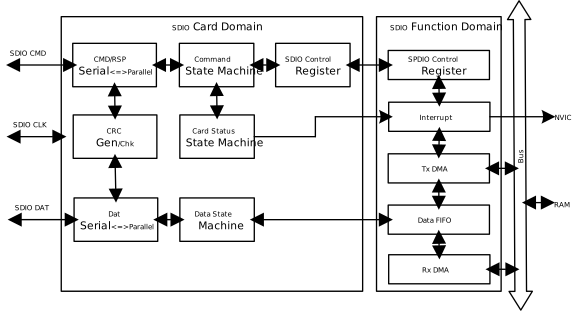
This IC supports only one function module, which is WLAN.
Note
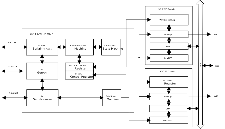
This IC supports two function modules: WLAN and Bluetooth.
Note
This IC supports two function modules: WLAN and Bluetooth.
SDIO Architecture
The structure of the SDIO interface is shown in the figure below:
Function Pin Groups
The SDIO interface has hardware flexibility, and its function pins are divided into multiple function groups.
Different development boards may provide different groups of pins, allowing developers to choose the appropriate pin group based on the hardware.
Pin Functions
CLK: Clock input pin for data synchronization.
CMD: Command input/response output pin for sending commands/receiving responses.
DAT0-DAT3: Data pins supporting 1-bit and 4-bit mode data transmission.
Pin Groups
Group |
CLK |
CMD |
DAT3 |
DAT2 |
DAT1 |
DAT0 |
|---|---|---|---|---|---|---|
0 |
PA16 |
PA15 |
PA14 |
PA13 |
PA18 |
PA17 |
1 |
PA29 |
PA28 |
PA27 |
PA26 |
PA31 |
PA30 |
2 (default) |
PB9 |
PB8 |
PB7 |
PB6 |
PB14 |
PB13 |
3 |
PB19 |
PB18 |
PB17 |
PA12 |
PB21 |
PB20 |
4 |
PB26 |
PB25 |
PB24 |
PB23 |
PB28 |
PB27 |
Group |
CLK |
CMD |
DAT3 |
DAT2 |
DAT1 |
DAT0 |
|---|---|---|---|---|---|---|
0 |
PA18 |
PA19 |
PA26 |
PA4 |
PA25 |
PA5 |
1(default) |
PA18 |
PA19 |
PA21 |
PA4 |
PA20 |
PA5 |
2 |
PA18 |
PA19 |
PA21 |
PA27 |
PA20 |
PA28 |
3 |
PA18 |
PA19 |
PA26 |
PA27 |
PA25 |
PA28 |
4 |
PA11 |
PA10 |
PA9 |
PA6 |
PA8 |
PA7 |
5 |
PB23 |
PB22 |
PB16 |
PB13 |
PB15 |
PB14 |
6 |
PC7 |
PC6 |
PC5 |
PC2 |
PC4 |
PC3 |
Group |
CLK |
CMD |
DAT3 |
DAT2 |
DAT1 |
DAT0 |
|---|---|---|---|---|---|---|
0(default) |
PA10 |
PA9 |
PA8 |
PA7 |
PA12 |
PA11 |
1 |
PA28 |
PA27 |
PA26 |
PA25 |
PA30 |
PA29 |
Note
Users can modify SDIO_Pin_Grp in the ameba_intfcfg.c file to select different pin groups, for more details please refer to
ameba_intfcfg
WHC
Ameba can be connected to the host MCU via SDIO to perform as a Wi-Fi card.
For more detailed information, please refer to Wi-Fi Card Mode .
Application Examples
Ameba SDK provides examples for SDIO device loopback test, helping users understand and utilize SDIO.
Users can run the loopback test examples to determine if the current hardware environment is functioning correctly.
The example code includes SDIO device example code and SD host example code based on Raspberry Pi.
SDIO Device Example Code
The example mbed_sdio_loopback_device demonstrates loopback test on the SDIO device side. Its main contents include:
Initialize the SDIO interface and function 1 (WLAN).
Initialize the transmit buffer and receive buffer for loopback test.
Set up the interrupt handler of the SDIO device to process received data in time and transmit data back to host.
SD Host Example Code
The example sdio_device_loopback_Raspberry demonstrates data communication with the SDIO device via SD host on a Raspberry Pi. Its main contents include:
Initialize SD host on the Raspberry Pi.
Identify and initialize the SDIO device and function 1 via the SD host.
Send data to function 1 of the SDIO device via the SD host continuously.
Receive data from function 1 of the SDIO device via the SD host continuously.
Note
For more details on the test, please refer to sdio_loopback_test_guide.pdf in the example path.
If users want to develop based on this example, please avoid occupying too much time in the tasks associated with the SDIO interrupt handler, which can prevent delays in handling interrupt-related events.
Raw API
SDIO Exported Types
-
struct SDIO_InitTypeDef
SDIO Init Structure Definition.
Public Members
-
u32 TXBD_BAR
Specifies TXBD base address
-
u32 TXBD_RING_SIZE
Specifies TXBD ring size, This parameter must be set to a value in the 0-0xFFFF range.
-
u32 TX_BUFFER_SIZE
Specifies TX buffer size, This parameter must be set to a value in the 0-0xFF range.
-
u32 RXBD_BAR
Specifies RXBD base address
-
u32 RXBD_RING_SIZE
Specifies RXBD ring size, This parameter must be set to a value in the 0-0xFFFF range.
-
u32 RXBD_FREE_TH
Specifies the threshold of free RX BD count to trigger interrupt.
-
u32 TXBD_BAR
-
struct SDIO_InitTypeDef
SDIO Init Structure Definition.
Public Members
-
u32 TXBD_BAR
Specifies TXBD base address
-
u32 TXBD_RING_SIZE
Specifies TXBD ring size, This parameter must be set to a value in the 0-0xFFFF range.
-
u32 TX_BUFFER_SIZE
Specifies TX buffer size, This parameter must be set to a value in the 0-0xFF range.
-
u32 RXBD_BAR
Specifies RXBD base address
-
u32 RXBD_RING_SIZE
Specifies RXBD ring size, This parameter must be set to a value in the 0-0xFFFF range.
-
u32 RXBD_FREE_TH
Specifies the threshold of free RX BD count to trigger interrupt.
-
u32 TX_AGG_DISPATCH
Specifies whether to enable TX aggregation dispatch function.
-
u32 TXBD_BAR
-
typedef struct SPDIO_ADAPTER *PSPDIO_ADAPTER
-
struct SPDIO_ADAPTER
SPDIO adapter structure containing all SDIO device state.
Public Members
-
void *spdio_priv
Private data from the user.
-
SPDIO_TX_BD_HANDLE *pTXBDHdl
Pointer to the allocated memory for the TX BD handle array.
-
SPDIO_TX_BD *pTXBDAddr
Start address of the TX BD array; must be 4-byte aligned.
-
u16 TXBDWPtr
Local write index of the SDIO TX (Host-to-Device) BD ring, distinct from the HW-maintained write index.
-
u16 TXBDRPtr
Read index of the SDIO TX (Host-to-Device) BD ring.
-
SPDIO_RX_BD_HANDLE *pRXBDHdl
Pointer to the allocated memory for the RX BD handle array.
-
SPDIO_RX_BD *pRXBDAddr
Start address of the RX BD array; must be 8-byte aligned.
-
u16 RXBDWPtr
Write index of the SDIO RX (Device-to-Host) BD ring.
-
u16 RXBDRPtr
Local read index of the SDIO RX (Device-to-Host) BD ring, distinct from the HW-maintained read index.
-
u16 host_rx_bd_num
Number of RX BDs on the host side.
-
u16 host_tx_bd_num
Number of TX BDs on the host side (data received from host).
-
u16 device_rx_bufsz
RX buffer size per BD: equals desired packet length plus 24 bytes (SPDIO header), must be a multiple of 64, maximum 16 KB.
-
u8 WaitForDeviceRxbuf
Flag indicating the device is waiting for an available RX buffer.
-
u8 TxOverFlow
Flag indicating a TX buffer overflow has occurred.
-
void *spdio_priv
-
struct SPDIO_RX_BD
RX Buffer Descriptor structure.
Public Members
-
u32 BuffSize
bit[13:0]: RX buffer size, maximum 16384-1.
-
u32 LS
bit[14]: Last Segment flag.
-
u32 FS
bit[15]: First Segment flag.
-
u32 Seq
bit[31:16]: Sequence number, reserved and unused.
-
u32 PhyAddr
Physical address of the RX buffer; must be 4-byte aligned.
-
u32 BuffSize
-
struct SPDIO_RX_BD_HANDLE
Handle structure binding a RX_BD with a RX packet.
Public Members
-
struct spdio_buf_t *dev_tx_buf
Pointer to the device transmit buffer associated with this RX BD.
-
SPDIO_RX_BD *pRXBD
Pointer to the RX BD buffer.
-
u8 isPktEnd
Indicates whether this BD is the last segment of a packet that spans more than one BD.
-
u8 isFree
Indicates whether this RX BD is free (DMA complete and the associated packet has been freed).
-
struct spdio_buf_t *dev_tx_buf
-
struct SPDIO_TX_BD_HANDLE
Handle structure binding a TX_BD with a TX packet.
Public Members
-
SPDIO_TX_BD *pTXBD
Pointer to the TX BD buffer.
-
struct spdio_buf_t *dev_rx_buf
Pointer to the device receive buffer associated with this TX BD.
-
u8 isPktEnd
Indicates whether this BD is the last segment of a packet that spans more than one BD.
-
u8 isFree
Indicates whether this TX BD is free.
-
SPDIO_TX_BD *pTXBD
-
struct spdio_buf_t
SPDIO buffer structure used for TX and RX data transfer.
Public Members
-
void *priv
Private data from user.
-
u32 buf_allocated
Allocated address of the SPDIO buffer.
-
u16 size_allocated
Actual allocated size of the buffer.
-
u32 buf_addr
Physical address of the SPDIO buffer, must be 4-byte aligned.
-
u16 buf_size
Size of valid data in the buffer.
-
u8 type
Data type carried by this buffer, refer to
spdio_rx_data_tandspdio_tx_data_t.
-
u8 reserved
Reserved.
-
void *priv
-
typedef s8 (*spdio_device_rx_done_cb_ptr)(PSPDIO_ADAPTER pSPDIODev, struct spdio_buf_t *buf, u8 *pdata, u16 pktsize, u8 type)
Callback function type invoked when SDIO device RX transfer from host completes.
-
typedef s8 (*spdio_device_tx_done_cb_ptr)(PSPDIO_ADAPTER pSPDIODev, struct spdio_buf_t *buf)
Callback function type invoked when SDIO device TX transfer to host completes.
SDIO Exported Constants
/* Check if the given device is a valid SDIO device. */
#define IS_SDIO_DEVICE ((x) == SDIO_WIFI)
/* DMA alignment requirement in bytes for SPDIO buffers. */
#define SPDIO_DMA_ALIGN_4 4

/* TX BD buffer size unit; must be a multiple of 64 bytes. */
#define SPDIO_TX_BD_BUF_SZ_UNIT 64

/* Threshold of free RX BDs before notifying the host. */
#define SPDIO_RX_BD_FREE_TH 5

/* Minimum number of RX BDs required to send a packet. */
#define SPDIO_MIN_RX_BD_SEND_PKT 1

/* Maximum buffer size a single RX BD can point to (4-byte aligned). */
#define SPDIO_MAX_RX_BD_BUF_SIZE 16380

/* Initial interrupt mask for SDIO device operation. */
#define SDIO_INIT_INT_MASK (SDIO_WIFI_BIT_H2C_DMA_OK | SDIO_WIFI_BIT_C2H_DMA_OK | \
    SDIO_WIFI_BIT_H2C_BUS_RES_FAIL | SDIO_WIFI_BIT_RX_BD_FLAG_ERR_INT | SDIO_NOTIFY_TYPE_INT)

/* Interrupt bits for SDIO WiFi notification events. */
#define SDIO_NOTIFY_TYPE_INT (SDIO_WIFI_BIT_H2C_MSG_INT | SDIO_WIFI_BIT_RPWM1_INT | \
    SDIO_WIFI_BIT_RPWM2_INT | SDIO_WIFI_BIT_HOST_WAKE_CPU_INT | SDIO_WIFI_BIT_H2C_SUS_REQ)

/* Checks whether x is a valid SDIO device (WiFi or BT). */
#define IS_SDIO_DEVICE (((x) == SDIO_WIFI) || ((x) == SDIO_BT))
SDIO EVENT Definitions
/* SDIO event: new RX packet ready */
#define SDIO_EVENT_RX_PKT_RDY (0x00000001 << 1)

/* SDIO event: enable periodic SDIO status dump */
#define SDIO_EVENT_DUMP (0x00000001 << 3)

/* SDIO event: request to exit the SDIO task */
#define SDIO_EVENT_EXIT (0x00000001 << 27)

/* SDIO event: SDIO MP task has stopped */
#define SDIO_EVENT_MP_STOPPED (0x00000001 << 28)

/* SDIO event: SDIO IRQ task has stopped */
#define SDIO_EVENT_IRQ_STOPPED (0x00000001 << 29)

/* SDIO event: SDIO TX task has stopped */
#define SDIO_EVENT_TX_STOPPED (0x00000001 << 30)

/* SDIO event: SDIO RX task has stopped */
#define SDIO_EVENT_RX_STOPPED (0x00000001 << 31)
Not supported.
SDIO Exported Functions
-
void SDIO_AbortRxReq(SDIO_TypeDef *SDIO)
Abort SDIO RX request.
- Parameters:
SDIO – SDIO device, refer to IS_SDIO_DEVICE() for valid values.
-
void SDIO_CPWM2_Set(SDIO_TypeDef *SDIO, u16 Val, u32 Newstate)
Set CPWM2 to host.
- Parameters:
SDIO – SDIO device, refer to IS_SDIO_DEVICE() for valid values.
Val – CPWM2 message to be sent.
Newstate – New state of CPWM2, which can be ENABLE or DISABLE.
-
u32 SDIO_DMA_CTRL_Get(SDIO_TypeDef *SDIO)
Get AHB DMA control register value.
- Parameters:
SDIO – SDIO device, refer to IS_SDIO_DEVICE() for valid values.
- Returns:
AHB DMA control register value.
-
void SDIO_DMA_Reset(SDIO_TypeDef *SDIO)
Reset SDIO DMA.
- Parameters:
SDIO – SDIO device, refer to IS_SDIO_DEVICE() for valid values.
-
u32 SDIO_H2C_MSG_Get(SDIO_TypeDef *SDIO)
Get H2C message from host.
- Parameters:
SDIO – SDIO device, refer to IS_SDIO_DEVICE() for valid values.
- Returns:
H2C message value.
-
void SDIO_INTClear(SDIO_TypeDef *SDIO, u16 SDIO_INT)
Clear specified SDIO interrupt bit(s).
- Parameters:
SDIO – SDIO device, refer to IS_SDIO_DEVICE() for valid values.
SDIO_INT – Specified interrupt bit(s) to be cleared.
-
void SDIO_INTClearAll(SDIO_TypeDef *SDIO)
Clear all the SDIO interrupt bits.
- Parameters:
SDIO – SDIO device, refer to IS_SDIO_DEVICE() for valid values.
-
void SDIO_INTConfig(SDIO_TypeDef *SDIO, u16 IntMask, u32 NewState)
Enable or disable specified interrupt source(s).
- Parameters:
SDIO – SDIO device, refer to IS_SDIO_DEVICE() for valid values.
IntMask – Specifies the interrupt source(s) to configure; refer to SPDIO_CPU_INT_MASK definitions for the target SDIO instance.
NewState – Interrupt status, which can be ENABLE or DISABLE.
-
u16 SDIO_INTStatus(SDIO_TypeDef *SDIO)
Get SDIO interrupt status.
- Parameters:
SDIO – SDIO device, refer to IS_SDIO_DEVICE() for valid values.
- Returns:
Interrupt status.
-
void SDIO_Init(SDIO_TypeDef *SDIO, SDIO_InitTypeDef *SDIOInit_Struct)
Initialize the SDIO according to the specified parameters in SDIO_InitStruct.
- Parameters:
SDIO – SDIO device, refer to IS_SDIO_DEVICE() for valid values.
SDIOInit_Struct – Pointer to an SDIO_InitTypeDef structure that contains the configuration information of the SDIO peripheral.
Note
Pinmux function and CCCR (if needed) should be configured before this function.
-
u8 SDIO_RPWM1_Get(SDIO_TypeDef *SDIO)
Get RPWM1 value from host.
- Parameters:
SDIO – SDIO device, refer to IS_SDIO_DEVICE() for valid values.
- Returns:
RPWM1 value.
-
u16 SDIO_RPWM2_Get(SDIO_TypeDef *SDIO)
Get RPWM2 value from host.
- Parameters:
SDIO – SDIO device, refer to IS_SDIO_DEVICE() for valid values.
- Returns:
RPWM2 value.
-
u16 SDIO_RXBD_RPTR_Get(SDIO_TypeDef *SDIO)
Get RXBD read pointer, which is updated by SDIO IP.
- Parameters:
SDIO – SDIO device, refer to IS_SDIO_DEVICE() for valid values.
- Returns:
RXBD read pointer.
-
void SDIO_RXBD_WPTR_Set(SDIO_TypeDef *SDIO, u16 Val)
Set RXBD write pointer, which is updated by CPU.
- Parameters:
SDIO – SDIO device, refer to IS_SDIO_DEVICE() for valid values.
Val – RXBD write pointer.
-
void SDIO_RxReq(SDIO_TypeDef *SDIO)
Set SDIO RX request.
- Parameters:
SDIO – SDIO device, refer to IS_SDIO_DEVICE() for valid values.
-
void SDIO_SetReady(SDIO_TypeDef *SDIO, int ready)
Set SDIO ready bit to tell host if SDIO is ready.
- Parameters:
SDIO – SDIO device, refer to IS_SDIO_DEVICE() for valid values.
ready – If SDIO is ready, which can be ENABLE or DISABLE.
-
void SDIO_StructInit(SDIO_InitTypeDef *SDIO_InitStruct)
Fill each SDIO_InitStruct member with its default value.
- Parameters:
SDIO_InitStruct – Pointer to an SDIO_InitTypeDef structure which will be initialized.
-
void SDIO_CPWM1_Set(SDIO_TypeDef *SDIO, u8 Val)
Set CPWM1 to host.
- Parameters:
SDIO – SDIO device, refer to IS_SDIO_DEVICE() for valid values.
Val – CPWM1 message to be sent.
-
u32 SDIO_TXBD_RPTR_Get(SDIO_TypeDef *SDIO)
Get TXBD read pointer.
- Parameters:
SDIO – SDIO device, refer to IS_SDIO_DEVICE() for valid values.
- Returns:
TXBD read pointer.
-
void SDIO_TXBD_RPTR_Set(SDIO_TypeDef *SDIO, u32 Val)
Set TXBD read pointer, which is updated by CPU.
- Parameters:
SDIO – SDIO device, refer to IS_SDIO_DEVICE() for valid values.
Val – TXBD read pointer.
-
u32 SDIO_TXBD_WPTR_Get(SDIO_TypeDef *SDIO)
Get TXBD write pointer, which is updated by SDIO IP.
- Parameters:
SDIO – SDIO device, refer to IS_SDIO_DEVICE() for valid values.
- Returns:
TXBD write pointer.
-
void SDIO_CPWM1_Set(SDIO_TypeDef *SDIO, u8 Val, u32 Newstate)
Set CPWM1 to host.
- Parameters:
SDIO – SDIO device, refer to IS_SDIO_DEVICE() for valid values.
Val – CPWM1 message to be sent.
Newstate – Reverse message or not, which can be ENABLE or DISABLE.
-
u16 SDIO_TXBD_RPTR_Get(SDIO_TypeDef *SDIO)
Get TXBD read pointer.
- Parameters:
SDIO – SDIO device, refer to IS_SDIO_DEVICE() for valid values.
- Returns:
TXBD read pointer.
-
void SDIO_TXBD_RPTR_Set(SDIO_TypeDef *SDIO, u16 Val)
Set TXBD read pointer, which is updated by CPU.
- Parameters:
SDIO – SDIO device, refer to IS_SDIO_DEVICE() for valid values.
Val – TXBD read pointer.
-
u16 SDIO_TXBD_WPTR_Get(SDIO_TypeDef *SDIO)
Get TXBD write pointer, which is updated by SDIO IP.
- Parameters:
SDIO – SDIO device, refer to IS_SDIO_DEVICE() for valid values.
- Returns:
TXBD write pointer.
-
void SDIO_C2H_MSG_EXT_Set(SDIO_TypeDef *SDIO, u32 Val)
Send C2H extended message to host.
- Parameters:
SDIO – SDIO device, refer to IS_SDIO_DEVICE() for valid values.
Val – Extended C2H message to be sent.
-
void SDIO_C2H_MSG_Set(SDIO_TypeDef *SDIO, u32 Val)
Send C2H message to host.
- Parameters:
SDIO – SDIO device, refer to IS_SDIO_DEVICE() for valid values.
Val – C2H message to be sent.
-
u32 SDIO_H2C_MSG_EXT_Get(SDIO_TypeDef *SDIO)
Get extended H2C message from host.
- Parameters:
SDIO – SDIO device, refer to IS_SDIO_DEVICE() for valid values.
- Returns:
Extended H2C message value.
-
void SDIO_RxBdHdl_Init(SPDIO_RX_BD_HANDLE *g_RXBDHdl, SPDIO_RX_BD *SPDIO_RXBDAddr, u16 host_rx_bd_num)
Initialize RX buffer descriptor handle array.
- Parameters:
g_RXBDHdl – Pointer to the RX BD handle array to be initialized.
SPDIO_RXBDAddr – Pointer to the RX BD buffer, must be 4-byte aligned.
host_rx_bd_num – Number of RX buffer descriptors.
-
void SDIO_TxBdHdl_Init(SPDIO_TX_BD_HANDLE *g_TXBDHdl, SPDIO_TX_BD *SPDIO_TXBDAddr, struct spdio_buf_t *spdio_dev_rx_buf, u16 host_tx_bd_num)
Initialize TX buffer descriptor handle array.
- Parameters:
g_TXBDHdl – Pointer to the TX BD handle array to be initialized.
SPDIO_TXBDAddr – Pointer to the TX BD buffer, must be 4-byte aligned.
spdio_dev_rx_buf – Pointer to the pre-allocated device receive buffer array.
host_tx_bd_num – Number of TX buffer descriptors.
-
void SDIO_Tx_AGG_Set(SDIO_TypeDef *SDIO, u32 Newstate)
Enable or disable Tx Agg function.
- Parameters:
SDIO – SDIO device, refer to IS_SDIO_DEVICE() for valid values.
Newstate – New state of Tx Agg function, which can be ENABLE or DISABLE.
-
u8 SPDIO_DeviceTx(SDIO_TypeDef *SDIO, PSPDIO_ADAPTER pSPDIODev, struct spdio_buf_t *pbuf)
Transmit data from device to host via SPDIO RX BD ring.
- Parameters:
SDIO – SDIO device, refer to IS_SDIO_DEVICE() for valid values.
pSPDIODev – Pointer to SPDIO adapter structure.
pbuf – Pointer to a spdio_buf_t structure which carries the payload.
- Returns:
Operation result:
TRUE: Success
FALSE: Fail
-
void SPDIO_Notify_INT(SDIO_TypeDef *SDIO, u16 IntStatus)
Handle SDIO interrupt status notification.
- Parameters:
SDIO – SDIO device, refer to IS_SDIO_DEVICE() for valid values.
IntStatus – Interrupt status bits to be handled.
-
void SPDIO_Recycle_Rx_BD(SDIO_TypeDef *SDIO, PSPDIO_ADAPTER pSPDIODev, spdio_device_tx_done_cb_ptr spdio_device_tx_done_cb)
Recycle SDIO RX buffer descriptors after host DMA is done.
- Parameters:
SDIO – SDIO device, refer to IS_SDIO_DEVICE() for valid values.
pSPDIODev – Pointer to SPDIO adapter structure.
spdio_device_tx_done_cb – Callback function called when RX BD is recycled.
Mbed API
MBED_SPDIO Exported Types
Structure Type
-
struct spdio_t
MBED SPDIO driver configuration and callback structure.
Public Members
-
SDIO_TypeDef *pSDIO
Pointer to SDIO hardware base address (SDIO_WIFI only).
-
void *priv
Reserved for internal use; not set by user.
-
u32 host_rx_bd_num
Number of host RX BDs for sending data to host; 2 BDs per packet, must be even.
-
u32 host_tx_bd_num
Number of host TX BDs for receiving data from host.
-
u32 device_rx_bufsz
RX buffer size: desired packet length + 24-byte SPDIO header; must be a multiple of 64.
-
struct spdio_buf_t *rx_buf
RX buffer array pre-allocated by user; total size = device_rx_bufsz * host_tx_bd_num.
-
char (*device_rx_done_cb)(void *priv, void *pbuf, u8 *pdata, u16 size, u8 type)
Callback function defined by user, called by SPDIO when one packet is received.
Parameters
priv: Pointer to spdio_t structure which is used to initialize the SPDIO interface.
pbuf: Pointer to spdio_buf_t structure which is the SPDIO receive buffer.
pdata: Actual received packet payload.
size: Actual payload length.
type: Received packet type, which should be a value of spdio_rx_data_t.
Returns: RTK_SUCCESS or RTK_FAIL.
-
char (*device_tx_done_cb)(void *priv, void *pbuf)
Callback function defined by user, called by SPDIO when one packet is sent.
Parameters
priv: Pointer to spdio_t structure which is used to initialize the SPDIO interface.
pbuf: Pointer to spdio_buf_t structure which carries the transmit packet.
Returns: RTK_SUCCESS or RTK_FAIL.
-
SDIO_TypeDef *pSDIO
-
struct spdio_buf_t
SPDIO buffer structure for TX and RX data transfer.
Public Members
-
void *priv
Private data from user.
-
u32 buf_allocated
Allocated address of the SPDIO buffer.
-
u16 size_allocated
Actual allocated size of the buffer.
-
u32 buf_addr
Physical address of the SPDIO buffer; must be 4-byte aligned.
-
u16 buf_size
Size of valid data in the buffer.
-
u8 type
Data type of the buffer payload; see spdio_rx_data_t and spdio_tx_data_t.
-
u8 reserved
Reserved.
-
void *priv
-
struct spdio_t
MBED SPDIO driver configuration and callback structure.
Public Members
-
SDIO_TypeDef *pSDIO
Pointer to SDIO hardware base address (SDIO_WIFI or SDIO_BT).
-
void *priv
Reserved for internal use; not set by user.
-
u32 host_rx_bd_num
Number of host RX BDs for sending data to host.
-
u32 host_tx_bd_num
Number of host TX BDs for receiving data from host.
-
u32 device_rx_bufsz
RX buffer size: desired packet length + 24-byte SPDIO header; must be a multiple of 64.
-
struct spdio_buf_t *rx_buf
RX buffer array pre-allocated by user; total size = device_rx_bufsz * host_tx_bd_num.
-
rtos_sema_t irq_sema
SDIO IRQ task semaphore.
-
rtos_task_t irq_task_hdl
SDIO IRQ task handle.
-
char (*device_rx_done_cb)(void *priv, void *pbuf, u8 *pdata, u16 size, u8 type)
Callback function defined by user, called by SPDIO when one packet is received.
Parameters
priv: Pointer to spdio_t structure which is used to initialize the SPDIO interface.
pbuf: Pointer to spdio_buf_t structure which is the SPDIO receive buffer.
pdata: Actual received packet payload.
size: Actual payload length.
type: Received packet type, which should be a value of spdio_rx_data_t.
Returns: RTK_SUCCESS or RTK_FAIL.
-
char (*device_tx_done_cb)(void *priv, void *pbuf)
Callback function defined by user, called by SPDIO when one packet is sent.
Parameters
priv: Pointer to spdio_t structure which is used to initialize the SPDIO interface.
pbuf: Pointer to spdio_buf_t structure which carries the transmit packet.
Returns: RTK_SUCCESS or RTK_FAIL.
-
SDIO_TypeDef *pSDIO
Enumeration Type
-
enum spdio_rx_data_t
Data type identifiers for SPDIO receive buffers.
Values:
/* No data type. */
SPDIO_RX_DATA_NULL = 0x00

/* Ethernet packet received. */
SPDIO_RX_DATA_ETH = 0x83

/* AT command packet received. */
SPDIO_RX_DATA_ATCMD = 0x11

/* User-defined data type. */
SPDIO_RX_DATA_USER = 0x41
-
enum spdio_tx_data_t
Data type identifiers for SPDIO transmit buffers.
Values:
/* No data type. */
SPDIO_TX_DATA_NULL = 0x00

/* Ethernet packet sent. */
SPDIO_TX_DATA_ETH = 0x82

/* AT command response packet sent. */
SPDIO_TX_DATA_ATCMDRSP = 0x10

/* User-defined data type. */
SPDIO_TX_DATA_USER = 0x40
Not supported.
MBED_SPDIO Exported Constants
/* DMA alignment requirement in bytes for SPDIO buffers. */
#define SPDIO_DMA_ALIGN_4 4

/* Align RX buffer size x to the next multiple of 64 bytes. */
#define SPDIO_RX_BUFSZ_ALIGN ((((x-1)>>6)+1)<<6)

/* Size of the SPDIO receive descriptor in bytes. */
#define SPDIO_RXDESC_SZ 24
MBED_SPDIO Exported Functions
-
void spdio_deinit(struct spdio_t *obj)
Deinitialize the SPDIO interface.
- Parameters:
obj – Pointer to a spdio_t structure which is already initialized.
-
void spdio_init(struct spdio_t *obj)
Initialize the SPDIO interface.
- Parameters:
obj –
Pointer to a spdio_t structure which should be initialized by user, and which will be used to initialize the SPDIO interface.
obj->host_rx_bd_num: Number of host RX BDs for device-to-host transfer.
obj->host_tx_bd_num: Number of host TX BDs for host-to-device transfer.
obj->device_rx_bufsz: Device RX buffer size (must be a multiple of 64).
obj->rx_buf: Device RX buffer array pre-allocated by user.
-
void spdio_structinit(struct spdio_t *obj)
Fill spdio_t structure with default settings.
- Parameters:
obj – Pointer to a spdio_t structure which will be filled with default settings.
-
void spdio_trigger_rx_handle(void)
Trigger SDIO to process a received packet when a free RX buffer is available.
-
s8 spdio_tx(struct spdio_t *obj, struct spdio_buf_t *pbuf)
Prepare RX buffer descriptor and notify the SD host.
- Parameters:
obj – Pointer to an initialized spdio_t structure.
pbuf – Pointer to a spdio_buf_t structure which carries the payload.
- Returns:
RTK_SUCCESS or RTK_FAIL.
-
u8 spdio_tx(struct spdio_t *obj, struct spdio_buf_t *pbuf)
Prepare RX buffer descriptor and notify the SD host.
- Parameters:
obj – Pointer to an initialized spdio_t structure.
pbuf – Pointer to a spdio_buf_t structure which carries the payload.
- Returns:
RTK_SUCCESS or RTK_FAIL.

