Ethernet
Supported ICs[ RTL8721F ]
Overview
Ethernet is a wired networking technology that complies with the IEEE 802.3 standard. The Ameba series chips integrate an IEEE 802.3 compliant MAC (Media Access Control) controller and connect to an external PHY (Physical Layer) chip via the RMII (Reduced Media Independent Interface), enabling access to the physical network.

Ethernet Architecture
Features
The current Ethernet module supports the following key features:
Interface Standards & Speed
Supports RMII interface standard.
Supports 10/100 Mbps speeds with Full-Duplex/Half-Duplex modes.
Supports hardware Auto-negotiation for speed and duplex modes.
Protocols & Flow Control
Full-Duplex: Supports IEEE 802.3x Flow Control.
Half-Duplex: Supports CSMA/CD (Carrier Sense Multiple Access with Collision Detection) protocol.
Operating Modes & Clocking
Supports configuring the RMII interface in MAC Mode or PHY Mode.
Supports outputting a 25/50MHz reference clock source, saving the need for an external PHY crystal.
Management & Advanced Features
Supports configuring and managing PHY devices via the SMI (MDC/MDIO) interface.
Supports SMI Master (STA) mode to control external PHYs.
Supports EEE (Energy Efficient Ethernet) standard.
Quick Start
Communication Interfaces
Communication between the Ameba MAC and the external world relies on two core interfaces: RMII for data transmission and SMI (MDC/MDIO) for configuration management.

RMII and SMI Interfaces
RMII Data Interface Signals
The Ameba chip connects to the external PHY chip via the RMII interface. The standard signal definitions and directions are described below.
Signal Name |
Abbr. |
Direction |
Description |
|---|---|---|---|
TX Data 0 |
TXD0 |
MAC ➔ PHY |
Transmit Data Bit 0. Lower bit of data transmitted from MAC to PHY. |
TX Data 1 |
TXD1 |
MAC ➔ PHY |
Transmit Data Bit 1. Higher bit of data transmitted from MAC to PHY. |
TX Enable |
TX_EN |
MAC ➔ PHY |
Transmit Enable. When high, indicates that valid data is present on TXD. |
RX Data 0 |
RXD0 |
PHY ➔ MAC |
Receive Data Bit 0. Lower bit of data transmitted from PHY to MAC. |
RX Data 1 |
RXD1 |
PHY ➔ MAC |
Receive Data Bit 1. Higher bit of data transmitted from PHY to MAC. |
RX Error* |
RX_ERR |
PHY ➔ MAC |
Receive Error. High when the PHY detects an error (e.g., coding error) in the current frame. |
CRS_DV |
CRS_DV |
PHY ➔ MAC |
Carrier Sense/Data Valid. Indicates the PHY is receiving data and the medium is not idle. |
Ref Clock |
REF_CLK |
Bi-dir |
50MHz Reference Clock. This is the core synchronization clock for RMII operation. |
Note
The IEEE 802.3u standard defines RX_ERR (Receive Error). When the PHY detects an error in a received packet, it asserts this signal to notify the MAC. However, in practice, to save pins (GPIO), the MAC controllers of many embedded SoCs do not use the hardware RX_ERR pin in RMII mode. Data integrity relies entirely on the Ethernet frame’s built-in CRC/FCS checksum mechanism.
RMII reduces the data bus from 4 bits to 2 bits, requiring fewer pins. The trade-off is a higher clock frequency: 50MHz instead of 25MHz, to maintain 100Mbps throughput.
RMII signals use REF_CLK for synchronization, so both MAC and PHY must reference the same clock source. In practice, the following REF_CLK architectures exist:
MAC supplies REF_CLK to PHY: MAC’s REF_CLK is Output; PHY’s REF_CLK is Input.
PHY supplies REF_CLK to MAC: MAC’s REF_CLK is Input; PHY’s REF_CLK is Output.
External Source supplies REF_CLK to both: Both MAC and PHY REF_CLK are set to Input.
See the figure below:

REF_CLK Direction
The specific direction setting depends on the clock source scheme. See PHY Clock Source Selection for details.
SMI Management Interface Signals
The SMI (Serial Management Interface), commonly known as the MDIO Interface, is a simple two-wire serial interface used for exchanging management data between the Ethernet MAC sublayer and the Physical Layer (PHY), with a maximum speed of 2.5MHz.
The MDIO interface uses a Master-Slave architecture containing two types of entities:
STA (Station Management Entity)
Typically integrated into the MAC controller.
Acts as the bus Master, initiating all management frames (Read/Write) and driving the clock signal (MDC).
MMD (MDIO Manageable Device) / PHY
Integrated into the Ethernet PHY chip.
Acts as the bus Slave, responding to read/write requests from the STA.
The MDIO interface consists of two signal lines:
Signal Name |
Abbr. |
Direction |
Description |
|---|---|---|---|
MDC |
MDC |
MAC ➔ PHY |
Management Data Clock. Provides the clock reference for MDIO data transfer (typically < 2.5MHz). |
MDIO |
MDIO |
Bi-dir |
Management Data Input/Output. Used to transfer configuration commands and status data. Requires an external pull-up resistor (typically 1.5kΩ). |
Tip
Aperiodic Clock: MDC does not need to be a continuous periodic signal. The STA can stop the clock between frame transmissions (holding high or low), and the PHY must support this static operation.
Frequency Independent: As long as the maximum frequency limit (2.5 MHz) is not exceeded, the interface can operate at any lower rate, allowing for software bit-banging of MDIO timing.
Operating Modes
The connection method between the Ethernet MAC controller and external devices depends on its operating mode.
MAC Mode
This is the default operating mode where the CPU’s integrated MAC connects to an external PHY chip, as shown in MAC connecting to external PHY chip. In this mode, Ameba’s RMII interface follows standard MAC definitions to drive TX signals and manage the external PHY via MDC/MDIO.

MAC connecting to external PHY chip
PHY Mode
When two MAC-equipped chips (e.g., SoC-to-SoC or SoC-to-switch) sit on the same PCB, using two PHY chips for interconnection increases BOM cost, power consumption, and PCB area.
Traditional Connection: Requires additional components, as shown below.

Traditional Connection
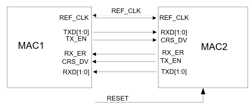
PHY Mode (MAC-to-MAC Direct Connection): The Ameba MAC controller can be configured in
PHY Mode. The connection diagram is shown in MAC to MAC Direct Connection. This mode saves PHY chips and transformers, significantly optimizing hardware architecture.

MAC to MAC Direct Connection
A typical schematic for this connection is shown below:
MAC to MAC Schematic Reference
Warning
PHY Mode Precautions
Disable Auto-negotiation: Without a PHY chip, auto-negotiation cannot be used. Speed and Duplex must be forced manually.
Cross Connection: Ensure TX/RX lines are crossed (TX connects to peer RX).
Common Clock Source: A common clock source strategy is strongly recommended. Either one SoC outputs 50MHz to the other, or both share a single external crystal source to avoid FIFO overflow or CRC errors due to clock frequency deviation (PPM).
Pin Configuration
The ameba_intfcfg.c file predefines 4 groups of Ethernet pin configurations (ETHERNET_PAD). Group 0 is used by default.
Pin Function |
Group 0 (Default) |
Group 1 |
Group 2 |
Group 3 |
|---|---|---|---|---|
RMII Signals |
(Fixed Set) |
(Fixed Set) |
(Fixed Set) |
(Fixed Set) |
REF_CLK |
PB_9 |
PB_18 |
PB_30 |
PB_18 |
TXD0 |
PB_8 |
PB_13 |
PB_29 |
PC_4 |
TXD1 |
PB_7 |
PB_16 |
PB_28 |
PC_3 |
TXEN |
PB_6 |
PB_15 |
PB_27 |
PC_2 |
RXD0 |
PB_11 |
PB_21 |
PC_0 |
PC_7 |
RXD1 |
PB_10 |
PB_19 |
PB_31 |
PC_6 |
RXERR |
PB_4 |
PB_17 |
PB_25 |
PB_17 |
CRS |
PB_5 |
PB_14 |
PB_26 |
PC_5 |
Mgmt & Clock |
||||
MDC |
PB_12 |
PB_22 |
PC_1 |
PA_25 |
MDIO |
PB_3 |
PB_23 |
PB_24 |
PA_26 |
EXTCLK |
PA_12 |
PB_24 |
PA_12 |
PB_19 |
EXTCLK is used to provide a clock to an external PHY chip. See PHY Clock Source Selection.
Note
All pin assignments under the RMII interface are fixed. Users need to check the pinmux table and modify the
ETHERNET_Pin_Grpvariable (0x0 - 0x3) inameba_intfcfg.cto select an available pin group based on the chip package.MDC, MDIO, and EXTCLK can be flexibly configured to other pins. Modify based on the pinmux table.
PHY Clock Source Selection
Ameba Supplies Clock to PHY
Configure a pin as EXT_CLK_OUT (the EXTCLK pin in Pin Configuration) via pin multiplexing. Ameba outputs a 25 MHz or 50 MHz clock to the PHY, so the PHY does not need a separate XTAL. In Menuconfig, select 50M from Ameba or 25M from Ameba accordingly.

Note
Alternative: REF_CLK to PHY XTAL2 (RTL8201FR only): REF_CLK can be connected to the PHY’s XTAL2 pin with XTAL1 tied to GND, saving the PHY crystal. In this case EXT_CLK_OUT is not used; the clock is carried on the REF_CLK line instead.

PHY Uses Independent XTAL
If the PHY’s system clock is provided by its own independent XTAL, EXT_CLK_OUT does not need to be configured. In Menuconfig, select PHY xtal.

Configuration Process
The Ameba SDK integrates the LwIP component, implementing the MAC layer driver (ameba_ethernet.c) and the PHY RTL8201FR driver (ameba_phy8201fr.c). When using a standard EVB, users can configure and use Ethernet as follows:
Menuconfig: Enable related components via
menuconfigbefore compiling.Go to
CONFIG ETHERNETand enable Ethernet.In
PHY SOURCE CLK, select the clock source based on the board hardware (see PHY Clock Source Selection).
PHY xtal: PHY clock is sourced from its own independent crystal. Select , save and exit.50M from Ameba/25M from Ameba: PHY clock is sourced from Ameba, output via theEXT_CLK_OUTpin (see Pin Configuration) at 50 MHz or 25 MHz. Go toPHY SOURCE CLK, select or , save and exit.
Pin and PHY Adaptation
If using a standard EVB, the SDK adapts to PHY RTL8201FR by default. Check the schematic and modify the
ETHERNET_Pin_Grpindex inameba_intfcfg.cto select theETHERNET_PAD[4][11]member used by the board.If using a custom board or other PHY chips:
Modify the
ETHERNET_Pin_Grpindex inameba_intfcfg.cbased on the actual pin combination.Add the PHY driver for the specific chip used. Refer to PHY Interface Adaptation.
Note
The default REF_CLK direction is MAC → PHY (Ameba outputs REF_CLK). If your board uses PHY → MAC direction, configure it accordingly in the initialization structure.
PHY Interface Adaptation
Software Architecture
Before adapting a PHY driver, it is essential to understand the Ethernet architectural layering. The Ameba Ethernet module integrates the Lightweight TCP/IP stack (LwIP) and MAC driver. The correspondence to OSI and TCP/IP models is shown below:

Ethernet Software Architecture
Layer functions:
Layer |
Component |
Description |
Core Files |
Note |
|---|---|---|---|---|
L5-7: App |
User App |
Implements user logic and high-level protocols (HTTP, MQTT). |
(User Defined) |
Socket/Netconn API |
L4: Transport |
TCP & UDP |
End-to-end communication; TCP for reliability, UDP for low latency. |
|
LwIP Core |
L3: Network |
IP & ARP |
Routing, logical addressing (IPv4/v6), address resolution. |
|
LwIP Core |
L2: Data Link |
LLC / Adapter |
Converts LwIP |
|
Porting Layer |
MAC Driver |
Manipulates MAC registers, manages DMA descriptors and interrupts. |
|
Platform Specific |
|
L1: Physical |
PHY Driver |
Configures external PHY transceiver, manages Auto-negotiation. |
|
Platform Specific |
HW Interface |
Physical bus between MAC and PHY. |
N/A |
RMII / MII |
Note
The L2 MAC driver and RMII operations are implemented in the SDK. RTL8201FR driver (L1) is provided.
Adaptation Steps
The Ameba SDK provides a flexible PHY abstraction layer, allowing users to adapt different Ethernet PHY chips by implementing the eth_phy_ops interface table and defining device instances.
Implement PHY Operations
Implement the key functions in struct eth_phy_ops based on the PHY datasheet.
Note
Standard PHY registers are defined in
ameba_phy.h.Custom registers can be defined in a user file (e.g.,
ameba_phy_custom.c).
Taking RTL8201FR as an example:
OPS Member |
Function |
Description |
Reason |
|---|---|---|---|
|
|
Init & ID Check Read PHY ID and match with |
Prevents matching wrong hardware; ensures PHY is powered and MDIO is working. |
|
|
Soft Reset Write BMCR reset bit and wait for stabilization. |
Ensures PHY is in a known state. |
|
|
Ref Clock Config Switch to Page 7 to set RMII clock direction (Input/Output). |
RMII requires a synchronized 50MHz clock. Wrong direction prevents link establishment. |
|
|
Link Config Configure Auto-Neg advertisement or force Speed/Duplex. |
Required to set 10M/100M or duplex modes. |
Define Bus Interface and PHY Instance
Define the MDIO bus read/write interface and create the eth_phy_dev instance, specifying the PHY address.
// 1. Define MDIO bus operations
// Use low-level read/write functions provided by SDK
const struct eth_mdio_ops eth_mdio_bus_default = {
.mdio_read = Ethernet_ReadPhyReg,
.mdio_write = Ethernet_WritePhyReg,
};
// 2. Define PHY device instance
struct eth_phy_dev eth_phy_dev_custom = {
.bus = ð_mdio_bus_default, // Bind bus interface
.addr = 0x01, // [Important] PHY Address must match schematic
.ops = &custom_phy_ops, // Bind operations implemented above
};
Register and Initialize
In the Ethernet initialization phase, call Ethernet_StructInit() passing the PHY instance.
void User_Ethernet_Init(void)
{
ETH_InitTypeDef eth_initstruct;
// Initialize using custom PHY device instance
// This mounts eth_phy_dev_custom to the MAC driver
Ethernet_StructInit(ð_initstruct, ð_phy_dev_custom);
// Call other Ethernet functions...
}
Functional Details
Auto-negotiation
Auto-negotiation allows devices on both ends of a link to automatically select common operating parameters:
Duplex Mode
Speed
Flow Control
Note
IEEE 802.3u makes auto-negotiation optional for 100Mbps Ethernet.
Detection Mechanism
Auto-negotiation uses pulses on the physical link:
NLP (Normal Link Pulse): Used for 10BASE-T link beat. Single 100ns pulse every 16ms ± 8ms.
FLP (Fast Link Pulse): Used for 100BASE-TX/1000BASE-T. Extends NLP into a “Burst”.
Structure: Burst every 16ms.
Encoding: 33 pulse positions (17 clock + 16 data).
Link Codeword: 16-bit word advertising speed/duplex capabilities.

Link Pulses and Codewords
Parallel Detection
Used when one side enables Auto-Neg and the other forces a fixed mode.
Principle: The Auto-Neg side detects FLP, NLP, and Idle streams.
NLP Detected: Determine peer is 10M.
4B/5B Idle Stream Detected: Determine peer is 100M.
Warning
Duplex Mismatch: Parallel detection cannot detect duplex mode. By standard, the Auto-Neg side must fallback to Half-Duplex.
Negotiation Scenarios
Link establishment depends on configuration:
Local Config |
Peer Config |
Result |
Explanation |
|---|---|---|---|
Auto-Neg |
Auto-Neg |
✅ Success |
Exchange capabilities, lock to highest common mode (e.g., 100M Full). |
Auto-Neg |
Fixed 10M/100M (Half) |
✅ Success |
Parallel detection sets local to Half-Duplex. Matches peer. |
Auto-Neg |
Fixed 10M/100M (Full) |
⚠️ Duplex Mismatch |
Link Up, but packet loss. Local falls back to Half-Duplex via parallel detection; peer is Full-Duplex. Causes collisions and CRC errors. |
Auto-Neg (Full Only) |
Auto-Neg (Half Only) |
❌ Fail |
No common capabilities. |
Fixed Mode A |
Fixed Mode B |
❌ Fail |
Mismatched speed or duplex prevents sync. |
If Auto-Neg is disabled, ensure parameters match exactly on both sides.
Note
Auto-Neg should be disabled for:
PHY Mode: Connecting to an external MAC requires fixed speed/duplex.
VLAN
VLANs (Virtual LANs) break the limitations of a flat broadcast domain:
Broadcast Storms: Limits broadcast packets to the VLAN.
Security: Provides logical isolation.

VLAN Application
VLAN Tagging adds a 4-byte tag to the frame to identify membership.
Frame Format
IEEE 802.1Q inserts a tag between the Source MAC and EtherType.

VLAN Frame Format
Fields:
Field |
Length |
Value |
Function |
Notes |
|---|---|---|---|---|
TPID |
2 Bytes |
Fixed |
Identifies the frame as an 802.1Q tagged frame. |
Devices that do not support 802.1Q typically drop frames with TPID |
PRI |
3 Bits |
0–7 (higher = higher priority) |
QoS priority. High-priority packets are forwarded first when congestion occurs. |
To set priority without a specific VLAN, set VID to |
CFI/DEI |
1 Bit |
|
Originally distinguished Ethernet / FDDI / Token Ring frames (CFI). Redefined as DEI (Drop Eligible Indicator) in IEEE 802.1Q-2011 to indicate drop priority. |
Ethernet always uses |
VID |
12 Bits |
0–4095
(1–4094 valid)
|
Identifies the VLAN the frame belongs to. |
Special values: |
QinQ (Double Tagging) uses an outer STAG (Service Tag) and inner CTAG (Customer Tag).
VLAN Frame Processing
Switch logic:
Ingress (Receive):
Untagged frame from Access Link -> Add PVID Tag -> Internal Switching.
Egress (Send):
Send to Access Link -> Strip Tag -> Send Untagged Frame.
Send to Trunk Link -> Keep Tag -> Send Tagged Frame.
VLAN Configuration
Ameba MAC supports hardware VLAN tag offload for egress insertion/removal and ingress stripping.
Note
Hardware limits:
Supports Double Tagging (STAG + CTAG). Triple Tag is not supported.
Egress: Single insertion/removal/remark per packet.
Ingress: Strips inner CTAG only; stripped tag info is stored in the RX descriptor.
Egress (TX) Configuration
Configure the target tag layer and the egress action:
Parameter |
Value |
Description |
|---|---|---|
|
|
Selects the tag layer for Insert/Remove/Remark. |
|
0x0001–0xFFFF |
STAG Protocol ID. Valid only when |
|
0–4094 |
Target VID used by hardware when the action is INSERT or REMARK_VID. |
|
See options below. |
Egress action. Determines how the MAC processes the VLAN tag before transmission. |
DefTxAction options:
Mode |
Function |
Typical Scenario |
|---|---|---|
Intact |
No modification (supports double-tag passthrough). |
Soft-Tagging: OS network stack handles tagging, hardware does not intervene; or Trunk Passthrough. |
Insert |
Insert a new tag into the packet. (Note: total tag count after insertion must not exceed the hardware limit, typically 2 layers.) |
Provider QinQ: add S-Tag outside user packet; or Port Default VLAN (PVID): hardware forces the default PVID. |
Remove |
Remove the specified tag from the packet. |
Access Port: strip tag to restore standard Ethernet frame; or QinQ Termination: strip outer S-Tag for the user side. |
Remark |
Preserve tag structure, replace VID only. |
VLAN Translation: hardware replaces VID directly for cross-domain communication. |
Configuration recommendations:
Standard internet access: use
INTACT; let the OS network stack handle tagging.Embedded gateway/router: if CPU load is high, use
REMOVE(LAN port) andINSERT(WAN port) to leverage hardware offload.
Ingress (RX) Configuration
RxStrip: Hardware stripping control.1: Enable stripping. Driver reads VLAN ID from the RX descriptor.0: Disable stripping. Received packet retains the full VLAN tag header.
Energy Efficient Ethernet (EEE)
EEE (Energy Efficient Ethernet, IEEE 802.3az) is a power management technology whose core mechanism is Low Power Idle (LPI). It allows network devices to enter a low-power state during idle intervals when the link is up but no data is being transmitted.
System Architecture
EEE requires coordination between the MAC layer (containing the LPI Client) and the PHY.

EEE Architecture
LPI Client (Policy Initiator)
Located in the MAC layer. Responsible for initiating LPI requests based on traffic load. The specific trigger implementation is vendor-defined.
PHY (Physical Layer)
Encodes RMII signals (e.g., 4B/5B or 8B/10B) and exchanges LPI state with the link partner over the physical medium.
Entering/Exiting LPI
The standard RMII interface removes the TX_ER pin present in MII, so LPI cannot be signaled using the standard IEEE 802.3az pin combination directly. Instead, LPI entry and exit are encoded via combinations of control signals (TX_EN / CRS_DV) and data bus (TXD[1:0] / RXD[1:0]). The timing is shown in LPI Signaling.

LPI Signaling
TX Path (MAC to PHY): MAC decides when the PHY enters or exits low-power mode.
Enter LPI: MAC drives
TX_EN=0,TXD=01. PHY detects this state and shuts down the analog TX circuit.Hold LPI: MAC maintains
TX_EN=0,TXD=01.Exit LPI: When MAC needs to transmit or a timer expires, MAC changes
TXD[1:0]from01to00(TX_ENstill 0). This signals a Wake Request. After the required wake-up time Twq, MAC assertsTX_ENand begins transmission.
RX Path (PHY to MAC): PHY monitors the remote link state and notifies MAC to enter or exit low-power mode.
Enter LPI: PHY detects an LPI signal from the remote end, pulls
CRS_DVlow, and drivesRXD[1:0]to01. MAC detectsCRS_DV=0,RXD=01and enters RX low-power mode.Hold LPI: PHY maintains
RXD[1:0]at01until the line state changes.Exit LPI: PHY detects an IDLE stream on the line and changes
RXD[1:0]from01back to00. MAC recovers the RX clock and decode logic, ready to receive the next frame.
When the RMII interface asserts the LPI signal, the PHY transitions through the following states:

LPI States
Sleep: Local PHY sends SLEEP codeword to notify the link partner.
Quiet:
General: PHY stops transmitting after sending SLEEP.
1000BASE-T: Both sides must exchange SLEEP before jointly entering Quiet.
Refresh: Periodic Refresh signals are sent during Quiet to maintain link parameters (e.g., equalizer coefficients, clock synchronization).
Wake: PHY sends Wake signal to notify the link partner to resume normal operation.
LPI Decision Makers
TX Path
Enter LPI: The MAC determines when to initiate an LPI request on the TX path (i.e., output
01encoding):HW Auto:
TX queue empty: Triggered immediately when the last packet is sent and no new packet arrives.
TX rate below threshold: Even if the queue is not empty, MAC may enter LPI and buffer packets to reduce frequent wake-up overhead.
Pause frame received: When a Flow Control Pause frame is received, MAC pauses transmission and may enter LPI to save power.
SW Force: Software forces MAC into LPI mode via register configuration, typically for debugging or special power management.
Exit LPI:
HW Auto wake: New packet enters TX queue, or high-priority queue has data — hardware immediately triggers the wake sequence.
SW Force wake: Software proactively exits LPI in anticipation of a data burst, to avoid hardware wake-up latency.
RX Path
RX LPI state is primarily controlled by the PHY; MAC operates passively. MAC manages internal RX circuit power by monitoring RMII signal changes.
Enter LPI: When MAC detects
CRS_DV=0&RXD=01, the internal RX clock domain logic stops, packet parsing halts, and MAC enters low-power state.Exit LPI: PHY detects IDLE or data on the line and drives
RXD[1:0]from01back to00.
Configuration Process
Prerequisites: Enable Auto-Neg, Full Duplex, PHY supports EEE.
Sleep/Wake Policy:
Sleep policy determines when the MAC initiates an LPI request. Select based on the application scenario:
Option |
Description |
Scenario |
|---|---|---|
|
Immediate (Default): Enter sleep as soon as the TX queue is empty. |
Most IoT scenarios. Lowest power, but frequent PHY state switching if traffic is bursty. |
|
Traffic Threshold: Enter sleep only when TX rate is below the configured threshold. |
Latency-sensitive scenarios. Avoids frequent sleep when packet inter-arrival time is short. |
|
Pause Frame: Enter sleep only while a Flow Control Pause frame has halted transmission. |
High-throughput scenarios. Sleep triggered by flow control. |
Wake policy determines when the MAC exits the low-power state:
Option |
Description |
Recommended Use |
|---|---|---|
|
Wake on Any Data (Default): Wake immediately when data is written to the TX buffer. |
Default. Safest and most general setting. |
|
Wake on High Priority Only: Normal data queues; only high-priority packets trigger wake-up. |
QoS scenarios with VLAN priority queuing. |
Traffic Threshold:
This configuration is valid only when the sleep policy is set to ETH_EEE_SLEEP_LOW_TRAFFIC.
It sets the TX traffic threshold to trigger EEE sleep via the TxTrafficThresh parameter (unit: Bytes). The device enters sleep mode when the transmitted traffic within the observation window falls below this threshold.
The calculation formula is as follows:
TxTrafficThresh = Round[(T_tx_rate × Rate) / 8]
T_tx_rate: The traffic observation time window (e.g., 10us).Rate: The current link speed (e.g., 100Mbps).
Example:
When T_tx_rate = 10us and the link speed is 100Mbps, the calculated threshold is 0x7D (125 Bytes). The default value is 0x3E.
Note
A larger threshold makes sleep easier to trigger; a smaller threshold makes sleep harder to trigger.
Test Modes
Loopback modes for debugging:
Binary |
Macro |
Mode |
Description |
|---|---|---|---|
|
|
Normal |
Normal operation. |
|
|
External (R2T) |
RX to TX. Forwards received RX packets directly to TX. Tests external physical connection. |
|
|
Internal (T2R) |
TX to RX. CPU sent data loops back to RX inside MAC. Does not pass to PHY. Tests driver/MAC logic. |

Loopback Test Modes
T2R Mode: Data is looped back directly within the MAC, bypassing the PHY. It is used to verify the internal logic of the MAC controller.
R2T Mode: Data transmitted to the PHY is looped back to the MAC internally at the PHY level (on the MII/RMII interface side). It is used to verify the physical connection between the MAC and the PHY (e.g., PCB traces, soldering).
Ethernet Descriptors
Descriptors are shared memory structures between software (driver) and hardware (DMA), enabling zero-copy transfers and CPU offload.

Descriptor Ring
Note
Memory Attribute: Descriptors should be in Non-cacheable SRAM (or DDR with MPU config) to avoid Cache Coherency issues.
Alignment: RX buffers must be 4-byte aligned.
Descriptor Format

Descriptor Format
OWN (Ownership Bit)
OWN = 1 (DMA): CPU has prepared data (TX) or buffer (RX). CPU must not touch.
OWN = 0 (CPU): DMA has completed operation. CPU can reclaim.
EOR (End of Ring)
EOR = 1: End of ring. DMA wraps around to base address.
Descriptor Configuration
Buffer Size: Calculated for Max Ethernet Frame + VLAN + CRC = 1522 Bytes. Aligned to cache line (32B) → 1536 Bytes.
Descriptor Count:
ETH_RxDescNum/ETH_TxDescNum. More descriptors handle burst traffic better but use more RAM.
Performance Data
Test conditions:
Storage: Code in PSRAM; descriptors in Non-Cache SRAM.
TCP: Receive window (TCP Window) = 23360 Bytes (16 × 1460 MSS).
UDP: TX delay = 0.
Buffer: Single packet buffer size = 1536 Bytes.
The table below shows UDP/TCP throughput at 100Mbps and 10Mbps in Full-Duplex and Half-Duplex modes:
Link Mode |
UDP TX |
UDP RX |
TCP TX |
TCP RX |
|---|---|---|---|---|
100Mbps Full-Duplex |
95.4 |
93.5 |
94.8 |
78.0 |
100Mbps Half-Duplex |
95.4 |
92.0 |
90.0 |
78.0 |
10Mbps Full-Duplex |
9.60 |
9.57 |
9.50 |
9.49 |
10Mbps Half-Duplex |
9.54 |
9.57 |
8.80 |
8.90 |
Note: Reference data only.
Raw API
ETHERNET Exported Types
-
struct ETH_EEE_InitTypeDef
ETH EEE (Energy Efficient Ethernet) Configuration Structure.
Public Members
-
u32 EnableTx
TX LPI Enable: 1=Enable MAC to enter TX LPI, 0=Disable
-
u32 EnableRx
RX LPI Enable: 1=Enable MAC to respond to PHY LPI, 0=Disable
-
u8 Tw_WakeTime
Tw: Wake-up time (Unit: 1us). Must be >= PHY spec (Typ: 30us)
-
u8 Tr_LpiInterval
Tr: LPI refresh time (Unit: 1us). Minimum duration for LPI signal
-
u8 Td_TxDelay
Td: Decision delay (Unit: 8us). Idle time before entering LPI
-
u8 Tp_PauseTime
Tp: Pause time (Unit: 1us). Default: 10us
-
u16 TxTrafficThresh
TX Traffic Threshold (Bytes). Formula: Round[(10us * Rate)/8]. For 100Mbps: Set 0x7D (125 Bytes)
-
ETH_EEE_SleepPolicy SleepPolicy
Auto-sleep policy selection.
-
ETH_EEE_WakePolicy WakePolicy
Auto-wake policy selection.
-
u32 EnableTx
-
enum ETH_EEE_SleepPolicy
EEE Auto-Sleep Policies (Enter LPI Mode) enumeration. These values map directly to ETH_EEE_CR1 register bits. Multiple policies can be ORed together if supported by hardware logic.
Values:
/* Enter LPI based on low traffic rate (requires Threshold) */
ETH_EEE_SLEEP_LOW_TRAFFIC = BIT_EEE_REQ_SET0

/* Enter LPI immediately when TX queue is empty (Recommended) */
ETH_EEE_SLEEP_QUEUE_EMPTY = BIT_EEE_REQ_SET1

/* Enter LPI when Flow Control Pause frame is received */
ETH_EEE_SLEEP_ON_PAUSE = BIT_EEE_REQ_SET2

/* Mask of all sleep policy bits. */
ETH_EEE_SLEEP_ALL_MASK = (BIT_EEE_REQ_SET0 | BIT_EEE_REQ_SET1 | BIT_EEE_REQ_SET2)
-
enum ETH_EEE_WakePolicy
EEE Auto-Wake Policies (Exit LPI Mode) enumeration. These values map directly to ETH_EEE_CR1 register bits. Multiple policies can be ORed together.
Values:
/* Wake up on any new data in TX queue */
ETH_EEE_WAKE_ANY_DATA = BIT_EEE_WAKE_SET0

/* Wake up only on high priority data */
ETH_EEE_WAKE_HIGH_PRIO = BIT_EEE_WAKE_SET1

/* Mask of all wake policy bits. */
ETH_EEE_WAKE_ALL_MASK = (BIT_EEE_WAKE_SET0 | BIT_EEE_WAKE_SET1)
-
struct ETH_InitTypeDef
ETH Init Structure. Contains configuration for both MAC and PHY, plus runtime buffers.
Public Members
-
struct eth_phy_dev *phy_dev
Pointer to the associated PHY device instance.
-
union ETH_InitTypeDef.eth_mac_config_u MacConfig
MAC core and flow control configuration.
-
union ETH_InitTypeDef.eth_vlan_config_u VlanConfig
VLAN tag handling configuration.
-
ETH_EEE_InitTypeDef *EEE_Config
Pointer to EEE configuration structure, NULL to disable EEE.
-
uint32_t PktFilter
Additional packet filter control word.
-
uint8_t DMA_TxThreshold
TX FIFO start-of-transmission threshold (see eth_tx_threshold).
-
uint8_t DMA_RxThreshold
RX FIFO almost-full threshold (see eth_rx_threshold).
-
uint8_t DMA_TxTriggerLevel
TX interrupt trigger packet count (see eth_trigger_level).
-
uint8_t DMA_RxTriggerLevel
RX interrupt trigger packet count (see eth_trigger_level).
-
uint32_t ETH_IntMaskAndStatus
Interrupt mask and status register value.
-
uint8_t ETH_MacAddr[6]
Local MAC address (6 bytes).
-
uint8_t *ETH_TxPktBuf
Pointer to TX packet buffer memory.
-
uint8_t *ETH_RxPktBuf
Pointer to RX packet buffer memory.
-
ETH_TxDescTypeDef *ETH_TxDesc
Pointer to TX descriptor ring.
-
ETH_RxDescTypeDef *ETH_RxDesc
Pointer to RX descriptor ring.
-
uint16_t ETH_TxDescNum
Number of TX descriptors (1-4096).
-
uint16_t ETH_RxDescNum
Number of RX descriptors (1-4096).
-
uint8_t ETH_TxDescCurrentNum
Index of the TX descriptor currently in use.
-
uint8_t ETH_RxDescCurrentNum
Index of the RX descriptor currently in use.
-
uint8_t ETH_RxFrameStartDescIdx
Descriptor index of the first segment of the current RX frame.
-
u32 ETH_RxFrameLen
Total length of the current received frame in bytes.
-
u32 ETH_TxFrameLen
Length of the last transmitted frame in bytes.
-
u32 ETH_RxSegmentCount
Number of descriptors used by the current received frame.
-
u16 ETH_TxBufSize
Size of each TX buffer in bytes.
-
u16 ETH_RxBufSize
Size of each RX buffer in bytes.
-
union ETH_InitTypeDef.eth_mac_config_u
-
uint32_t Raw
Raw 32-bit value for MAC configuration register.
-
struct ETH_InitTypeDef.eth_mac_config_u.eth_mac_config_bits Bits
Named bitfield access for MAC configuration.
-
struct ETH_InitTypeDef.eth_mac_config_u.eth_mac_config_bits
-
-
uint32_t Loopback
Loopback mode (see eth_loopback_mode).
-
uint32_t IFGTime
Inter-frame gap setting (see eth_ifg_time).
-
uint32_t RefClkDir
Reference clock direction (see eth_refclk_dir).
-
uint32_t RefClkPhase
Reference clock sampling phase (see eth_refclk_phase).
-
uint32_t RxJumbo
Jumbo frame RX enable (see eth_rx_jumbo_cfg).
-
uint32_t PktFilterConfig
Packet filter mode (see eth_packet_filter_mode).
-
uint32_t AutoNego
Auto-negotiation enable (see eth_auto_nego).
-
uint32_t Duplex
Forced duplex mode when AutoNego=0 (see eth_duplex).
-
uint32_t FlowCtrl
Flow control mode (see eth_flow_ctrl_mode).
-
uint32_t FlowForce
Force flow control settings (see eth_flow_force).
-
uint32_t EEEEnable
1 = enable Energy Efficient Ethernet (EEE).
-
uint32_t Reserved
Reserved.
-
uint32_t Loopback
-
uint32_t Raw
-
union ETH_InitTypeDef.eth_vlan_config_u
-
uint32_t Raw
Raw 32-bit value for VLAN configuration register.
-
struct ETH_InitTypeDef.eth_vlan_config_u.eth_vlan_config_bits Bits
Named bitfield access for VLAN configuration.
-
struct ETH_InitTypeDef.eth_vlan_config_u.eth_vlan_config_bits
-
uint32_t RxStrip
RX VLAN tag stripping enable (see eth_vlan_strip).
-
uint32_t TxTagType
TX VLAN tag type: 0=C-TAG, 1=S-TAG (see eth_vlan_type).
-
uint32_t STagPID
S-TAG Protocol ID for QinQ frames (default 0x88A8).
-
uint32_t Reserved
Reserved.
-
uint32_t RxStrip
-
uint32_t Raw
-
struct eth_phy_dev *phy_dev
-
struct ETH_LoopBackTest
Ethernet hardware loopback test control and status.
Public Members
-
uint32_t DataPattern
Test data pattern byte value.
-
uint32_t DisableTxCRC
1 = disable CRC insertion on TX.
-
uint32_t PktNumSel
Packet count select: 0=100 packets, 1=1 packet, 2=5 packets.
-
uint32_t PktLenSel
Packet length select: 0=random, 1=64B fixed.
-
uint32_t Status_Fail
Test status: 1 = failure detected.
-
uint32_t Status_Done
Test status: 1 = test finished.
-
uint32_t DataPatSel
Data pattern source: 0=random, 1=fixed.
-
uint32_t Enable
1 = enable loopback test function.
-
uint32_t Reserved
Reserved.
-
uint32_t DataPattern
-
struct ETH_PktMetaDef
Ethernet packet metadata structure covering all TX/RX descriptor features. Strictly 4-byte aligned to prevent compiler padding and optimize cache. Currently only length and VLAN features are implemented in TX/RX functions.
Public Members
-
u32 pkt_len
TX/RX: Packet length in bytes.
-
u8 tx_keep
TX: 1 = skip switch lookup, transmit directly.
-
u8 tx_blu
TX: 1 = L2 bridging lookup only (when tx_keep=0).
-
u8 tx_dislrn
TX: 1 = disable source MAC address learning.
-
u8 tx_lgsen
TX: 1 = enable large send offload (TSO/LSO).
-
u16 tx_lgmss
TX: Maximum segment size for large send offload.
-
u8 csum_ip
TX/RX: IP checksum offload control (TX) or error status (RX).
-
u8 csum_l4
TX/RX: L4 (TCP/UDP) checksum offload control (TX) or error status (RX).
-
u8 cpu_tag_en
TX/RX: 1 = CPU tag present or to be inserted.
-
u8 cputag_psel
TX: CPU tag port selection.
-
u8 cputag_pri
TX: CPU tag priority value (0-7).
-
u8 vlan_valid
TX/RX: 1 = VLAN info in this descriptor is valid.
-
u16 vlan_tci
TX/RX: VLAN tag control information (PCP, DEI, VID).
-
u8 vlan_act
TX: VLAN egress action (see eth_vlan_action).
-
u8 pppoe_valid
TX/RX: 1 = PPPoE info in this descriptor is valid.
-
u8 pppoe_act
TX: PPPoE egress action.
-
u8 pppoe_idx
TX: PPPoE session table index.
-
u8 src_ext_port
TX/RX: Source extension port number.
-
u8 dst_port_mask
TX/RX: Destination port mask for multicast/forwarding.
-
u8 strm_id
TX/RX: PON stream ID.
-
u8 rx_pkt_type
RX: Received packet type (see eth_packet_type).
-
u8 rx_reason
RX: Trap or drop reason code.
-
u8 rx_int_prio
RX: Internal priority assigned by the switch.
-
u8 rx_crc_err
RX: 1 = CRC error detected in received frame.
-
u8 reserved[3]
Padding for 4-byte alignment.
-
u32 pkt_len
-
struct ETH_RxDescTypeDef
Rx Descriptor Structure.
Public Members
-
uint32_t dw1
Word 0: receive status and frame length.
-
uint32_t addr
Word 1: buffer address.
-
uint32_t dw2
Word 2: extended receive status (VLAN, PON).
-
uint32_t dw3
Word 3: source/destination port and reason code.
-
uint32_t dw1
-
struct ETH_TxDescTypeDef
Tx Descriptor Structure.
Public Members
-
uint32_t dw1
Word 0: status and command flags.
-
uint32_t addr
Word 1: buffer address.
-
uint32_t dw2
Word 2: VLAN tag and timestamp info.
-
uint32_t dw3
Word 3: destination port info.
-
uint32_t dw4
Word 4: large send (LSO) configuration.
-
uint32_t dw1
-
typedef struct ETH_InitTypeDef *PETH_InitTypeDef
-
enum eth_auto_nego
Auto-negotiation (NWay) enable/disable.
Values:
/* Disable auto-negotiation; use forced mode. */
ETH_NWAY_DISABLE = 0

/* Enable auto-negotiation (NWay). */
ETH_NWAY_ENABLE = 1
-
typedef void (*eth_callback_t)(u32 event, u32 data)
Function pointer type for the ETH event callback.
-
enum eth_duplex
Ethernet link duplex mode.
Values:
/* Half-duplex mode. */
ETH_HALF_DUPLEX = 0

/* Full-duplex mode. */
ETH_FULL_DUPLEX = 1
-
enum eth_flow_ctrl_mode
Ethernet flow control mode.
Values:
/* Flow control disabled. */
ETH_FLOW_OFF = 0

/* TX flow control only: send PAUSE frames. */
ETH_FLOW_TX_ONLY = 1

/* RX flow control only: respect received PAUSE frames. */
ETH_FLOW_RX_ONLY = 2

/* Full flow control: both TX and RX enabled. */
ETH_FLOW_FULL = 3
-
enum eth_flow_force
Flow control force mode, used when auto-negotiation is disabled.
Values:
/* Flow control from auto-negotiation result. */
ETH_FLOW_AUTO = 0

/* Force flow control settings regardless of NWay. */
ETH_FLOW_FORCE = 1
-
enum eth_ifg_time
Inter-frame gap (IFG) time between consecutive transmissions.
Values:
/* IFG setting 0: minimum inter-frame gap. */
ETH_IFG_0 = 0

/* IFG setting 1. */
ETH_IFG_1 = 1

/* IFG setting 2. */
ETH_IFG_2 = 2

/* IFG setting 3: standard (9.6 us for 10 Mbps, 960 ns for 100 Mbps). */
ETH_IFG_3 = 3

/* IFG setting 4. */
ETH_IFG_4 = 4

/* IFG setting 5. */
ETH_IFG_5 = 5

/* IFG setting 6. */
ETH_IFG_6 = 6

/* IFG setting 7: maximum inter-frame gap. */
ETH_IFG_7 = 7
-
enum eth_link_event
Ethernet event flags indicating link and data-path status.
Values:
/* No event pending. */
ETH_EVT_NO_EVENT = 0

/* Packet received successfully. */
ETH_EVT_RX_DONE = (1 << 0)

/* Packet transmitted successfully. */
ETH_EVT_TX_DONE = (1 << 1)

/* Link status changed. */
ETH_EVT_LINK_CHG = (1 << 2)

/* RX overflow or runt error occurred. */
ETH_EVT_RX_ERROR = (1 << 3)

/* TX error occurred. */
ETH_EVT_TX_ERROR = (1 << 4)

/* RX descriptor unavailable for Ring1. */
ETH_EVT_RDU_RING1 = (1 << 5)

/* RX descriptor unavailable for Ring2. */
ETH_EVT_RDU_RING2 = (1 << 6)

/* RX descriptor unavailable for Ring3. */
ETH_EVT_RDU_RING3 = (1 << 7)

/* RX descriptor unavailable for Ring4. */
ETH_EVT_RDU_RING4 = (1 << 8)

/* RX descriptor unavailable for Ring5. */
ETH_EVT_RDU_RING5 = (1 << 9)

/* RX descriptor unavailable for Ring6. */
ETH_EVT_RDU_RING6 = (1 << 10)

/* Alias for Ring1 RDU event. */
ETH_EVT_RX_NO_DESC = ETH_EVT_RDU_RING1
-
enum eth_loopback_mode
Loopback Modes for debugging.
Values:
/* Normal operation, no loopback. */
ETH_LPB_NONE = 0x0

/* External line loopback: RX data echoed to TX. */
ETH_LPB_R2T_EXT = 0x1

/* Internal loopback: TX data fed back to RX. */
ETH_LPB_T2R_INT = 0x3
-
enum eth_mode
Ethernet operating mode.
Values:
/* Operates as MAC connected to external PHY (MDIO master). */
ETH_MAC_MODE

/* Operates as PHY connected to external MAC (MDIO slave). */
ETH_PHY_MODE
-
enum eth_packet_filter_mode
Ethernet packet reception filter mode.
Values:
/* Accept unicast (physical match) and broadcast. Standard mode for most applications. */
ETH_FILTER_DEFAULT_UNICAST = 0

/* Accept unicast, broadcast, and multicast. Required for IPv6, PTP, or video streaming. */
ETH_FILTER_WITH_MULTICAST

/* Accept only packets matching this MAC address, ignoring broadcast. Used in strict security scenarios. */
ETH_FILTER_STRICT_UNICAST

/* Accept all valid packets regardless of destination MAC. Used for packet sniffing or software bridging. */
ETH_FILTER_PROMISCUOUS

/* Accept all packets including error/runt frames. For hardware debugging; WARNING: High CPU load. */
ETH_FILTER_DIAGNOSTIC_ALL
-
enum eth_packet_type
Defines the type of ethernet packet.
Values:
/* Pure Ethernet frame (non-IP). */
ETH_PKT_ETHERNET = 0

/* IPv4 packet. */
ETH_PKT_IPV4 = 1

/* IPv4 over PPTP. */
ETH_PKT_IPV4_PPTP = 2

/* IPv4 with ICMP payload. */
ETH_PKT_IPV4_ICMP = 3

/* IPv4 with IGMP payload. */
ETH_PKT_IPV4_IGMP = 4

/* IPv4 with TCP payload. */
ETH_PKT_IPV4_TCP = 5

/* IPv4 with UDP payload. */
ETH_PKT_IPV4_UDP = 6

/* IPv6 packet. */
ETH_PKT_IPV6 = 7

/* IPv6 with ICMPv6 payload. */
ETH_PKT_ICMPV6 = 8

/* IPv6 with TCP payload. */
ETH_PKT_IPV6_TCP = 9

/* IPv6 with UDP payload. */
ETH_PKT_IPV6_UDP = 10
-
struct eth_phy_dev
PHY Device Instance.
Public Members
-
const struct eth_mdio_ops *bus
Associated MDIO Bus
-
const struct eth_phy_ops *ops
Driver operations
-
phy_link_config_t link_cfg
Current Link Configuration
-
uint8_t addr
PHY Address (0-31)
-
phy_link_cb_t link_cb
Registered link state change callback, NULL if not set.
-
void *cb_user_data
User-supplied context pointer passed to link_cb.
-
const struct eth_mdio_ops *bus
-
struct eth_phy_ops
PHY Driver Operation Table (VTable)
Public Members
-
int (*init)(struct eth_phy_dev *dev)
Initialize the PHY (Check ID, basic setup)
-
int (*reset)(struct eth_phy_dev *dev)
Perform Software Reset (Register reset)
-
int (*cfg_link)(struct eth_phy_dev *dev, const phy_link_config_t *cfg)
Configure Link Parameters (Speed, Duplex, Auto-Neg, Pause)
-
int (*get_link)(struct eth_phy_dev *dev, phy_link_state_t *state)
Get Current Link Status.
-
int (*autoneg_restart)(struct eth_phy_dev *dev)
Restart Auto-Negotiation.
-
int (*cfg_refclock)(struct eth_phy_dev *dev, enum eth_refclk_dir dir)
Configure reference clock(REF_CLK) direction.
-
int (*cfg_eee)(struct eth_phy_dev *dev, uint32_t new_state)
Configure EEE (Energy Efficient Ethernet)
-
int (*get_eee_cap)(struct eth_phy_dev *dev, phy_eee_capability_t *cap)
Get PHY EEE Capabilities.
-
int (*set_loopback)(struct eth_phy_dev *dev, bool enable)
Enable/Disable Loopback Mode.
-
int (*set_link_callback)(struct eth_phy_dev *dev, phy_link_cb_t cb, void *user_data)
Register Link State Callback.
-
int (*init)(struct eth_phy_dev *dev)
-
enum eth_phy_rx_setup
PHY RX data setup time relative to the clock edge.
Values:
/* PHY RX setup time: 8 ns. */
ETH_PHY_RX_SETUP_TIME_8NS = 0x8

/* PHY RX setup time: 10 ns (default). */
ETH_PHY_RX_SETUP_TIME_10NS = 0x9

/* PHY RX setup time: 12 ns. */
ETH_PHY_RX_SETUP_TIME_12NS = 0x6

/* PHY RX setup time: 14 ns. */
ETH_PHY_RX_SETUP_TIME_14NS = 0x7

/* PHY RX setup time: 16 ns. */
ETH_PHY_RX_SETUP_TIME_16NS = 0x4

/* PHY RX setup time: 18 ns. */
ETH_PHY_RX_SETUP_TIME_18NS = 0x5
-
enum eth_phy_tx_setup
PHY TX data setup time relative to the clock edge.
Values:
/* PHY TX setup time: 6 ns. */
ETH_PHY_TX_SETUP_TIME_6NS = 0x6

/* PHY TX setup time: 8 ns. */
ETH_PHY_TX_SETUP_TIME_8NS = 0x5

/* PHY TX setup time: 10 ns (default). */
ETH_PHY_TX_SETUP_TIME_10NS = 0x4

/* PHY TX setup time: 12 ns. */
ETH_PHY_TX_SETUP_TIME_12NS = 0x3

/* PHY TX setup time: 14 ns. */
ETH_PHY_TX_SETUP_TIME_14NS = 0x2

/* PHY TX setup time: 16 ns. */
ETH_PHY_TX_SETUP_TIME_16NS = 0x1

/* PHY TX setup time: 18 ns. */
ETH_PHY_TX_SETUP_TIME_18NS = 0x0
-
enum eth_phy_type
Supported PHY Transceivers.
Values:
/* Realtek RTL8201 PHY. */
ETH_PHY_RTL8201 = 0

/* Realtek RTL8211 PHY. */
ETH_PHY_RTL8211 = 1

/* Realtek RTL8721F integrated PHY. */
ETH_PHY_RTL8721F = 2

/* Realtek RTL8721G integrated PHY. */
ETH_PHY_RTL8721G = 3

/* Microchip LAN8720 PHY. */
ETH_PHY_LAN8720 = 4

/* Microchip KSZ8081 PHY. */
ETH_PHY_KSZ8081 = 5

/* Generic IEEE 802.3 compliant PHY. */
ETH_PHY_GENERIC = 6
-
enum eth_refclk_dir
RMII reference clock direction.
Values:
/* REF_CLK driven by PHY to MAC. */
ETH_REFCLK_PHY2MAC = 0x00

/* REF_CLK driven by MAC to PHY. */
ETH_REFCLK_MAC2PHY = 0x01
-
enum eth_refclk_phase
RMII reference clock sampling edge.
Values:
/* Data sampled on REF_CLK rising edge. */
ETH_SAMPLED_ON_RISING_EDGE = 0x00

/* Data sampled on REF_CLK falling edge. */
ETH_SAMPLED_ON_FALLING_EDGE = 0x01
-
enum eth_rx_jumbo_cfg
RX jumbo frame reception enable.
Values:
/* Jumbo frame reception disabled. */
ETH_RX_JUMBO_DISABLE = 0x0

/* Jumbo frame reception enabled (max 16384 bytes). */
ETH_RX_JUMBO_ENABLE = 0x1
-
enum eth_rx_threshold
RX FIFO almost-full threshold.
Values:
/* RX FIFO threshold: 1024 bytes. */
ETH_RX_THRESHOLD_1024B = 0

/* RX FIFO threshold: 128 bytes. */
ETH_RX_THRESHOLD_128B = 1

/* RX FIFO threshold: 256 bytes. */
ETH_RX_THRESHOLD_256B = 2

/* RX FIFO threshold: 512 bytes. */
ETH_RX_THRESHOLD_512B = 3
-
enum eth_speed
Ethernet link speed.
Values:
/* 100 Mbps link speed. */
ETH_SPEED_100M = 0

/* 10 Mbps link speed. */
ETH_SPEED_10M = 1
-
enum eth_sys_hw_ctrl_e
Ethernet system-level hardware power and clock control targets.
Values:
/* FE PHY IP power control. */
ETH_SYS_HW_FEPHY_IP

/* FE MAC IP power control. */
ETH_SYS_HW_FEMAC_IP

/* UABG analog block enable. */
ETH_SYS_HW_UABG_EN

/* UAHV analog block enable. */
ETH_SYS_HW_UAHV_EN

/* FE PHY enable. */
ETH_SYS_HW_FEPHY_EN

/* Lexra bus clock enable. */
ETH_SYS_HW_LX_EN
-
typedef void (*eth_task_yield)(void)
Function pointer type for the ETH task yield handler.
-
enum eth_trigger_level
Number of packets to accumulate before raising an interrupt.
Values:
/* Interrupt after 1 packet. */
ETH_TRIGGER_LEVEL_1_PKT = 0

/* Interrupt after 4 packets. */
ETH_TRIGGER_LEVEL_4_PKTS = 1

/* Interrupt after 8 packets. */
ETH_TRIGGER_LEVEL_8_PKTS = 2

/* Interrupt after 12 packets. */
ETH_TRIGGER_LEVEL_12_PKTS = 3

/* Interrupt after 16 packets. */
ETH_TRIGGER_LEVEL_16_PKTS = 4

/* Interrupt after 20 packets. */
ETH_TRIGGER_LEVEL_20_PKTS = 5

/* Interrupt after 24 packets. */
ETH_TRIGGER_LEVEL_24_PKTS = 6

/* Interrupt after 28 packets. */
ETH_TRIGGER_LEVEL_28_PKTS = 7
-
enum eth_tx_threshold
TX FIFO start-of-transmission threshold.
Values:
/* TX FIFO threshold: 128 bytes. */
ETH_TX_THRESHOLD_128B = 0

/* TX FIFO threshold: 256 bytes. */
ETH_TX_THRESHOLD_256B = 1

/* TX FIFO threshold: 512 bytes. */
ETH_TX_THRESHOLD_512B = 2

/* TX FIFO threshold: 1024 bytes. */
ETH_TX_THRESHOLD_1024B = 3
-
enum eth_vlan_action
Defines Tx Descriptor VLAN action.
Values:
/* No VLAN header modification. */
ETH_VLAN_HDR_INTACT = 0

/* Insert VLAN tag into the frame. */
ETH_VLAN_HDR_INSERT = 1

/* Remove VLAN tag from the frame. */
ETH_VLAN_HDR_REMOVE = 2

/* Remark VLAN ID in the existing tag. */
ETH_VLAN_HDR_REMARK_VID = 3
-
enum eth_vlan_strip
Rx VLAN Stripping Control. Controls BIT_RXVLAN (Bit 2).
Values:
/* VLAN tag preserved in received payload. */
ETH_VLAN_STRIP_DISABLE = 0

/* VLAN tag stripped by hardware on reception. */
ETH_VLAN_STRIP_ENABLE = 1
-
enum eth_vlan_type
VLAN Tag Type Definition for Transmit (Tx). Controls BIT_TDSC_VLAN_TYPE (Bit 15).
Values:
/* C-TAG: customer tag with TPID 0x8100. */
ETH_VLAN_TYPE_CTAG = 0

/* S-TAG: service tag (QinQ) with configurable TPID. */
ETH_VLAN_TYPE_STAG = 1
-
enum phy_clock_source_t
PHY Clock Source (Platform Specific)
Values:
/* Uses external crystal oscillator. */
PHY_CLK_XTAL = 0

/* Uses 25 MHz oscillator. */
PHY_CLK_OSC_25M

/* Uses 50 MHz oscillator as RMII reference clock. */
PHY_CLK_OSC_50M
-
enum phy_duplex_t
PHY Duplex Mode.
Values:
/* PHY half-duplex mode. */
PHY_DUPLEX_HALF = 0

/* PHY full-duplex mode. */
PHY_DUPLEX_FULL = 1
-
enum phy_eee_mode_t
EEE (Energy Efficient Ethernet) Modes.
Values:
/* EEE disabled. */
PHY_EEE_DISABLE = 0

/* Enable EEE via auto-negotiation. */
PHY_EEE_ENABLE_AN

/* Enable LPI (low power idle) signaling only. */
PHY_EEE_ENABLE_LPI
-
typedef void (*phy_link_cb_t)(struct eth_phy_dev *dev, phy_link_state_t state, void *user_data)
Link State Change Callback.
-
struct phy_link_config_t
PHY Link Configuration (For forcing mode)
Public Members
-
bool autoneg_en
true: Auto-Negotiation, false: Fixed Mode
-
phy_speed_t speed
Speed (valid only if autoneg_en == false)
-
phy_duplex_t duplex
Duplex (valid only if autoneg_en == false)
-
bool advertise_100m
Advertise 100M ability
-
bool advertise_10m
Advertise 10M ability
-
bool advertise_pause
Advertise Pause frame capability
-
bool advertise_asym_pause
Advertise Asymmetric Pause capability
-
bool autoneg_en
-
struct phy_link_state_t
PHY Link Status.
Public Members
-
bool link_up
Link is Up
-
phy_speed_t speed
Current Speed
-
phy_duplex_t duplex
Current Duplex
-
bool pause_tx
Flow Control: TX Pause enabled
-
bool pause_rx
Flow Control: RX Pause enabled
-
bool link_up
-
enum phy_speed_t
PHY Link Speed.
Values:
/* PHY link speed 10 Mbps. */
PHY_SPEED_10M = 10

/* PHY link speed 100 Mbps. */
PHY_SPEED_100M = 100

/* PHY link speed 1000 Mbps. */
PHY_SPEED_1000M = 1000
ETHERNET Exported Constants
/* Ethernet MAC address length in bytes. */
#define ETH_MAC_ADDR_LEN (6)

/* Ethernet frame header length in bytes. Dest(6) + Src(6) + Type(2) */
#define ETH_HEADER_LEN (14)

/* IEEE 802.1Q VLAN tag length in bytes. */
#define ETH_VLAN_TAG_LEN (4)

/* CRC field length in bytes. */
#define ETH_CRC_LEN (4)

/* Minimum Ethernet payload length in bytes. */
#define ETH_PAYLOAD_MIN_LEN (46)

/* Maximum standard Ethernet payload length in bytes. */
#define ETH_PAYLOAD_MAX_LEN (1500)

/* Maximum jumbo frame payload length in bytes. */
#define ETH_JUMBO_FRAME_PAYLOAD_LEN (16 * 1024)

/* Maximum total Ethernet frame size including header, VLAN, payload, and CRC. */
#define ETH_PKT_MAX_SIZE (ETH_HEADER_LEN + ETH_VLAN_TAG_LEN + ETH_PAYLOAD_MAX_LEN + ETH_CRC_LEN)

/* Maximum aligned buffer size for one Ethernet frame. */
#define ETH_MAX_BUF_SIZE ((ETH_PKT_MAX_SIZE + CACHE_LINE_SIZE) & ~(CACHE_LINE_SIZE - 1))

/* C-VLAN (802.1Q) header template value with TPID 0x8100. */
#define ETH_C_VLAN_HDR 0x8100279F

/* S-VLAN (QinQ) header template value. */
#define ETH_S_VLAN_HDR 0x88A8279F

/* TX DMA descriptor size in bytes (5 words). */
#define ETH_TX_DESC_SIZE 20

/* RX DMA descriptor size in bytes (4 words). */
#define ETH_RX_DESC_SIZE 16

/* Polling interval in microseconds when checking descriptor own bit. */
#define ETH_OWN_BIT_UPDATE_PERIOD 10

/* Maximum loop count before a hardware operation times out. */
#define ETH_TIMEOUT_CNT_MAX 1000000

/* MDIO bus operation wait time in microseconds. */
#define MDIO_WAIT_TIME 64

/* Wait condition: SMI write operation completed. */
#define WAIT_SMI_WRITE_DONE 0

/* Wait condition: SMI read operation completed. */
#define WAIT_SMI_READ_DONE 1

/* Wait condition: RMII link up detected. */
#define WAIT_RMII_LINKUP 2
ETHERNET Exported Functions
-
void Ethernet_AutoPolling(u32 opt)
Enable or disable MDIO auto-polling of the PHY status registers.
- Parameters:
opt –
This parameter can be one of the following values:
ENABLE: Enable auto-polling.
DISABLE: Disable auto-polling (required before manual MDIO read/write).
-
void Ethernet_ClearAllINT(void)
Clear all pending interrupt status bits. Usually called during initialization or error recovery.
-
void Ethernet_ClearINT(uint32_t int_events)
Clear specified interrupt events. Converts software events back to hardware register write-1-to-clear.
- Parameters:
int_events – Bitmask of events to clear.
-
u32 Ethernet_GetLinkStatus(void)
Get the Ethernet link status.
- Returns:
1 for link up, 0 for link down.
-
u32 Ethernet_GetPendingINT(void)
Get currently pending and enabled interrupt events. Converts hardware register bits to logical software events.
- Returns:
Bitmask of pending events (eth_link_event).
-
u8 *Ethernet_GetRXPktInfo(ETH_InitTypeDef *ETH_InitStruct, ETH_PktMetaDef *meta)
Get the current RX packet buffer address and extract packet metadata.
- Parameters:
ETH_InitStruct – Pointer to Ethernet initialization structure containing the RX descriptor ring and current index.
meta – Pointer to metadata structure to be populated by the driver.
- Returns:
Packet buffer address, or NULL if no complete frame is available.
-
void Ethernet_GetSpeedDuplex(void)
Get speed and duplex of ethernet.
-
u8 *Ethernet_GetTXPktInfo(ETH_InitTypeDef *ETH_InitStruct)
Get the TX packet buffer address of the current TX descriptor.
- Parameters:
ETH_InitStruct – The pointer to ETH_InitTypeDef.
- Returns:
The TX packet buffer address, or NULL if no descriptor is available.
-
int Ethernet_Init(ETH_InitTypeDef *ETH_InitStruct)
Initialize Ethernet MAC, PHY, and DMA descriptors.
- Parameters:
ETH_InitStruct – Pointer to ETH_InitTypeDef containing the full Ethernet configuration.
- Returns:
RTK_SUCCESS on success, or a negative error code:
-RTK_ERR_BADARG if ETH_InitStruct, phy_dev, or phy_dev->ops is NULL.
-RTK_ERR_TIMEOUT if MAC reset or auto-negotiation timed out.
-
int Ethernet_ReadPhyReg(uint8_t phy_addr, uint8_t reg_addr, uint16_t *data)
Read data from MDIO bus (Clause 22).
- Parameters:
phy_addr – PHY address (0-31).
reg_addr – Register address (0-31).
data – Pointer to store the read value.
- Returns:
RTK_SUCCESS on success, negative error code on failure.
-
void Ethernet_SetDescAddr(ETH_InitTypeDef *ETH_InitStruct)
Set the start address of the TX/RX descriptor ring.
- Parameters:
ETH_InitStruct – The pointer to ETH_InitTypeDef.
-
void Ethernet_SetMacAddr(u8 *ETH_MacAddr)
Set the Ethernet MAC address.
- Parameters:
ETH_MacAddr – The MAC address pointer.
-
void Ethernet_SetRefclkDirec(u32 refclk_mode)
Set the Ethernet RMII reference clock direction.
- Parameters:
refclk_mode – Reference clock direction. See eth_refclk_dir.
-
void Ethernet_StructInit(ETH_InitTypeDef *ETH_InitStruct, struct eth_phy_dev *PHY_Dev)
Initialize ETH_InitTypeDef.
- Parameters:
ETH_InitStruct – The pointer to ETH_InitTypeDef.
PHY_Dev – The pointer to eth_phy_dev.
-
void Ethernet_UpdateRXDESC(ETH_InitTypeDef *ETH_InitStruct)
Return the current RX descriptor to DMA (supports jumbo frames).
- Parameters:
ETH_InitStruct – The pointer to ETH_InitTypeDef.
-
void Ethernet_UpdateTXDESCAndSend(ETH_InitTypeDef *ETH_InitStruct, ETH_PktMetaDef *meta)
Update the TX descriptor with metadata and trigger packet transmission.
- Parameters:
ETH_InitStruct – Pointer to Ethernet initialization structure.
meta – Pointer to packet metadata (Length, VLAN, etc.).
-
void Ethernet_UseExtClk(u32 pin)
Use external 50M clock as the RMII reference source clock.
- Parameters:
pin – The pin used to input the external 50MHz clock signal. It must be a pin that supports the EXT_CLK50M_IN pinmux function.
-
int Ethernet_WritePhyReg(uint8_t phy_addr, uint8_t reg_addr, uint16_t data)
Write data to MDIO bus (Clause 22).
- Parameters:
phy_addr – PHY address (0-31).
reg_addr – Register address (0-31).
data – Data to write.
- Returns:
RTK_SUCCESS on success, negative error code on failure.
