Infrared Radiation (IR)
Supported ICs[ RTL8721Dx ][ RTL8730E ][ RTL8721F ][ RTL8720F ]
Overview
The Infrared Radiation (IR) module is a controller used for infrared transmission and reception. It supports half-duplex communication and features hardware modulation and automatic capture of infrared signals.
Operating Modes
Transmit Mode : Hardware-based modulation, sends infrared signals via the TX port. Programmable control of carrier parameters.
Receive Mode : Supports both learning mode and normal receive mode, corresponding to infrared photodiode and infrared receiver module as hardware front-ends.
Working Principle
Signal Model
To simplify understanding of infrared signals, they can be categorized into the following symbol types:
Carrier Symbol :
Description: A signal containing a number of carrier clock cycles over a certain period.
Characteristics: The modulated signal that actually propagates through the physical medium.
Space Symbol :
Description: A signal maintaining a continuous high or low level over a certain period.
Characteristics: Represents the digital signal before modulation or after demodulation.

IR Signal Model
Transmission Mode
Principles of Signal Transmission
In transmission mode, accurate modulation and transmission of the signal are ensured through the following configurations:
Carrier Frequency Configuration:
Set the base frequency for signal modulation to provide stable transmission performance.
Space Symbol Configuration:
Define the space symbols of the signal by writing the duration of the high and low levels into the TX FIFO.
Together, these configurations determine the final signal output waveform, as illustrated below:
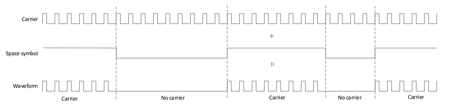
TX Workflow Diagram
Parsing TX FIFO Data
The TX FIFO data is 32 bits wide and contains the following information:
Field |
Description |
Parameter Meaning |
|---|---|---|
BIT[31] |
Carrier Transmission |
1: Transmit carrier 0: Do not transmit carrier |
BIT[30] |
Data End Flag |
1: Last packet 0: Normal packet |
BIT[29:28] |
Compensation Mode |
0: Non-carrier phase, count periods using system clock 3: Non-carrier phase, count periods using specified compensation frequency 1, 2: Not recommended |
BIT[27:0] |
Period count of carrier/non-carrier |
Counted by carrier frequency or compensation frequency |
Where the field BIT[27:0] is calculated as follows:
BIT[27:0] = fcarrier * Tduration
Parameter Meaning:
- fcarrier:
Carrier frequency (in Hertz)
- Tduration:
Duration of carrier or non-carrier symbol (in seconds)
Note
Compensation Mechanism: Effective only for the non-carrier phase in TX counting.
Compensation Mode: Using mode1 or mode2 is not recommended.
Organizing TX FIFO Data
Introduction to NEC Encoding Protocol
The NEC encoding protocol format comprises 2 start symbols, 64 data symbols, and 1 stop symbol. Specifically:
Logical 1 : Consists of a 560µs high-level signal followed by a (2250-560)µs low-level signal.
Logical 0 : Consists of a 560µs high-level signal followed by a (1120-560)µs low-level signal.
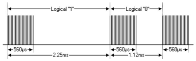
NEC Modulation
Below is an example configuration using the NEC encoding protocol with a 38KHz carrier frequency and a compensation mode set to 0, illustrating how to organize the data to be written into the TX FIFO.
Transmitting Logical 1 :
Write the following two groups of data into TX FIFO:
Entry |
BIT[31] |
BIT[30] |
BIT[29:28] |
BIT[27:0] |
|---|---|---|---|---|
First |
1 |
0 |
0 |
38 * 560 / 1000 = 21 |
Second |
0 |
0 |
0 |
38 * (1690 - 560) / 1000 = 63 |
Transmitting Logical 0 :
Write the following two groups of data into TX FIFO:
Entry |
BIT[31] |
BIT[30] |
BIT[29:28] |
BIT[27:0] |
|---|---|---|---|---|
First |
1 |
0 |
0 |
38 * 560 / 1000 = 21 |
Second |
0 |
0 |
0 |
38 * (1120 - 560) / 1000 = 21 |
Stopping Transmission :
To stop data transmission, set BIT[30]=1 in the last packet of the TX FIFO; the current data packet will still be sent.
Entry |
BIT[31] |
BIT[30] |
BIT[29:28] |
BIT[27:0] |
|---|---|---|---|---|
First |
1 |
1 |
0 |
38 * 560 / 1000 = 21 |
Reception Mode
Signal Reception Principle
The reception module monitors the duration (in sampling cycles) of the input high/low level signals and stores this information in the RX FIFO for software use.
The RX FIFO contents and their interpretation change depending on the selected reception mode:
Learning Mode :
The input signal contains the carrier wave.
The IR core captures carrier symbols.
The software needs to demodulate and decode to extract information such as carrier frequency and duty cycle.
Normal Reception Mode :
The front-end filters out the carrier wave.
The IR core captures space symbols .
No software demodulation is needed , simplifying subsequent parsing and processing.
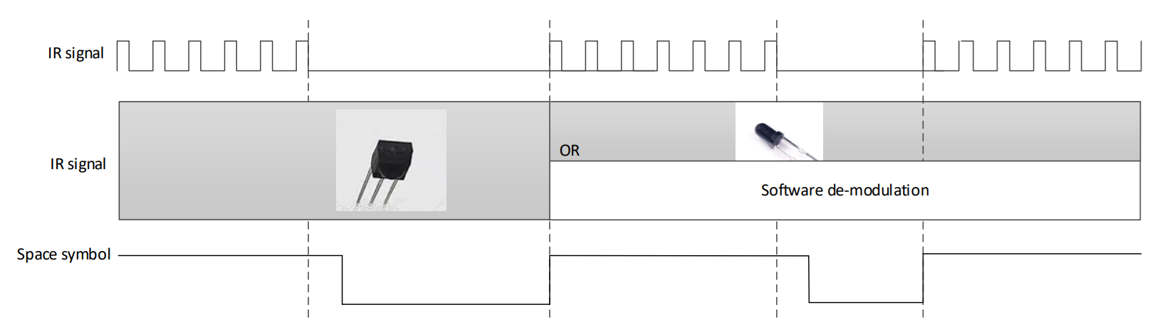
RX workflow diagram—comparison between Learning Mode and Normal Reception Mode
Parsing RX FIFO Data
The RX FIFO data is 32 bits wide and contains the following two pieces of information:
Field |
Description |
|---|---|
BIT[31] |
Signal level state received
|
BIT[30:0] |
Number of sampling clock cycles in the current signal level state
|
For example, under a sampling rate of 10 MHz (clock period of 100 ns):
Data |
RX FIFO Value |
Meaning |
|---|---|---|
Data 1 |
0X10001000 |
Indicates approximately 409.6 μs of high-level signal |
Data 2 |
0X00A1644 |
Indicates approximately 66.106 ms of low-level signal |
Start Conditions for Reception
Manual Reception : Allows manual control of the reception process.
Automatic Reception :
Trigger Condition Configuration:
Rising edge, falling edge, or any signal change.
Functionality:
The hardware will automatically start the reception process when a configured trigger is detected on the RX input signal.
Stop Conditions for Reception
Once preset conditions are met, the RX module will trigger a specific interrupt event.
Depending on system design, the interrupt handler can directly turn off the IR or release a semaphore to notify a corresponding thread to complete the IR shutdown.
Related settings include:
Signal Level State for Termination :
Explicitly define which level states will trigger the reception stop.
Duration Requirement for Signal Level State :
Define the minimum time the level state needs to be maintained to trigger the interrupt.
Enable RX Counter Threshold Interrupt :
Ensure that the RX module can trigger an IR_BIT_RX_CNT_THR_INT_STATUS interrupt once the specified level and duration are detected.
For example, the following configuration will cause the RX module to generate this interrupt event when it detects an input signal of low-level state with a duration of not less than approximately 66.1 ms:
/* Sampling rate of 10MHz */
IR_InitStruct.IR_Freq = 10000000;

/* Condition 1: Level signal state */
IR_InitStruct.IR_RxCntThrType = IR_RX_COUNT_LOW_LEVEL;

/* Condition 2: Threshold of level signal duration, set to around 66.1ms */
IR_InitStruct.IR_RxCntThr = 0xa1644;

/* Condition 3: Enable RX Counter threshold interrupt */
IR_INTConfig(IR_DEV, IR_BIT_RX_CNT_THR_INT_EN, ENABLE);
Carrier Problem in Rx Learning
Due to the characteristics of transistor, the response speed will slow down when the transistor works in deep saturation area.
Therefore, when carrier frequency is set too large, the hardware has the risk of receiving carrier waveform failed in receiving end.
In Rx learning, the maximum carrier frequency that can achieve is related to Rx circuit and the choice of transistor.
The circuit we suggested in Circuit of IR can support the maximum carrier frequency 70kHz, but you can choose the better transistor to acquire higher supported carrier frequency.
Schematic Design Guide
Leakage
To avoid the leakage problem, we suggest using the IR circuit below.
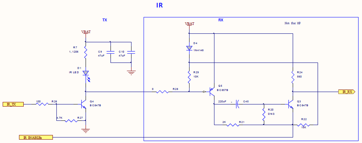
Circuit of IR
Development Process
Transmission
Set Pins
Refer to the Function Mux section for detailed information to ensure proper pin connections.
Configure Carrier Frequency and Duty Cycle
Configure appropriately according to the communication protocol’s requirements.
Configure TX FIFO
Used to control the duration of space symbols for hardware modulation.
Reception
Set Pins
Refer to the Function Mux section for detailed information to ensure proper pin connections.
Configure Sampling Frequency
Ensure that the reception module can accurately capture and record the input signal into the RX FIFO.
Configure Method to Trigger Reception
Configure Conditions to Stop Reception
Select RX FIFO Processing Strategy
Refer to Signal Reception Principle to choose based on the selected front-end hardware module.
Turn Off IR
Turn off the IR receiver when the termination conditions defined in step4 are met.
Example Applications
The SDK provides the following examples to help developers understand and use IR functions:
raw_ir_rx_learning demonstrates how to use the IR
RX learningmode.raw_ir_tx_nec_polling demonstrates how to send data using IR
polling mode.raw_ir_tx_nec_interrupt demonstrates how to send data using IR
interrupt mode.
Note
To check the IC supported by the examples, please refer to the README.md file under each example’s path.
Raw API
IR Exported Types
-
struct IR_InitTypeDef
IR Init Structure Definition.
Public Members
-
u32 IR_Clock
Specifies the IR IP core Input clock.
-
u32 IR_Freq
Specifies the clock frequency. This parameter is IR carrier frequency whose unit is Hz. This parameter can be a value of IR Carrier Frequency
-
u32 IR_DutyCycle
Specifies the IR duty cycle.
-
u32 IR_TxIdleLevel
Specifies the IR output level in Tx mode This parameter can be a value of IR Idle Level
-
u32 IR_TxInverse
Specifies inverse FIFO data or not in TX mode This parameter can be a value of IR Tx Data Level
-
u32 IR_TxFIFOThrLevel
Specifies TX FIFO interrupt threshold in TX mode. When TX FIFO depth <= threshold value, trigger interrupt. This parameter can be a value of IR Tx Threshold
-
u32 IR_TxCOMP_CLK
Specifies TX compensation clk. This CLK used when IR_Tx_DATA_TYPE = IR_TX_CLK_Self_Def.
-
u32 IR_RxStartMode
Specifies Start mode in RX mode This parameter can be a value of IR Rx Start Control
-
u32 IR_RxFIFOThrLevel
Specifies RX FIFO interrupt threshold in RX mode. When RX FIFO depth > threshold value, trigger interrupt. This parameter can be a value of IR Rx Threshold
-
u32 IR_RxFIFOFullCtrl
Specifies data discard mode in RX mode when RX FIFO is full and receiving new data This parameter can be a value of IR Rx FIFO Discard
-
u32 IR_RxTriggerMode
Specifies trigger in RX mode This parameter can be a value of IR Rx Auto Trigger Type
-
u32 IR_RxFilterTime
Specifies filter time in RX mode This parameter can be a value of IR Rx Filter Time
-
u32 IR_RxCntThrType
Specifies counter level type when trigger IR_INT_RX_CNT_THR interrupt in RX mode This parameter can be a value of IR Rx Count Level
-
u32 IR_RxCntThr
Specifies counter threshold value when trigger IR_INT_RX_CNT_THR interrupt in RX mode
-
u32 IR_Clock
-
typedef struct IR_InitTypeDef *PIR_InitTypeDef
IR Exported Constants
IR Carrier Frequency
/* Minimum IR carrier frequency in Hz. */
#define IR_TX_FREQ_HZ_MIN (25000)

/* Check if IR carrier frequency is valid. */
#define IS_IR_FREQUENCY ((F) >= IR_TX_FREQ_HZ_MIN)
IR Idle Level
/* TX idle output level is low. */
#define IR_IDLE_OUTPUT_LOW (0)

/* TX idle output level is high. */
#define IR_IDLE_OUTPUT_HIGH (1)
IR Mode
/* IR transmit mode. */
#define IR_MODE_TX (0)

/* IR receive mode. */
#define IR_MODE_RX (1)

/* Set IR mode field. */
#define IR_MODE ((MODE) & IR_BIT_MODE_SEL)
IR Rx Auto Trigger Type
/* RX triggered on falling edge. */
#define IR_RX_FALL_EDGE (0)

/* RX triggered on rising edge. */
#define IR_RX_RISING_EDGE (1)

/* RX triggered on both edges. */
#define IR_RX_DOUBLE_EDGE (2)

/* Check if IR Rx trigger edge value is valid. */
#define IS_IR_RX_TRIGGER_EDGE (((TRIGGER) == IR_RX_FALL_EDGE) || \
    ((TRIGGER) == IR_RX_RISING_EDGE) || \
    ((TRIGGER) == IR_RX_DOUBLE_EDGE))
IR Rx Count Level
/* Count threshold triggered on low level. */
#define IR_RX_COUNT_LOW_LEVEL (0)

/* Count threshold triggered on high level. */
#define IR_RX_COUNT_HIGH_LEVEL (1)
IR Rx FIFO Discard
/* Discard newest data when RX FIFO full. */
#define IR_RX_FIFO_FULL_DISCARD_NEWEST (1)

/* Discard oldest data when RX FIFO full. */
#define IR_RX_FIFO_FULL_DISCARD_OLDEST (0)
IR Rx INT Operation
/* Enable bits for all RX interrupts. */
#define IR_RX_INT_ALL_EN ((u32)0x0000003F)

/* Clear bits for all RX interrupts. */
#define IR_RX_INT_ALL_CLR ((u32)0x0000003F)

/* Mask bits for all RX interrupts. */
#define IR_RX_INT_ALL_MASK ((u32)0x000FC000)

/* Check if RX interrupt mask value is valid. */
#define IS_RX_INT_MASK (((MASK) & (~IR_RX_INT_ALL_MASK)) == 0)

/* Check if RX interrupt enable value is valid. */
#define IS_RX_INT (((MASK) & (~IR_RX_INT_ALL_EN)) == 0)

/* Check if RX interrupt clear value is valid. */
#define IS_RX_INT_CLR (((MASK) & (~IR_RX_INT_ALL_CLR)) == 0)
IR Rx Start Control
/* RX manual start mode. */
#define IR_RX_MANUAL_MODE (0)

/* RX auto trigger start mode. */
#define IR_RX_AUTO_MODE (1)
IR Rx Threshold
/* IR RX FIFO depth in entries. */
#define IR_RX_FIFO_SIZE (32)
IR Tx Data Level
/* Normal data, normal carrier output. */
#define IR_TX_DATA_NORMAL_CARRIER_NORMAL (0)

/* Normal data, inverted carrier output. */
#define IR_TX_DATA_NORMAL_CARRIER_INVERSE (1)

/* Inverted data, normal carrier output. */
#define IR_TX_DATA_INVERSE_CARRIER_NORMAL (2)

/* Inverted data, inverted carrier output. */
#define IR_TX_DATA_INVERSE_CARRIER_INVERSE (3)

/* Set TX data type and carrier inversion bits. */
#define IR_TX_DATA_TYPE_SET ((u32)(((x) << 13) & (IR_BIT_TX_OUTPUT_INVERSE | IR_BIT_TX_DE_INVERSE)))
IR Tx INT Operation
/* Mask bits for all TX interrupts. */
#define IR_TX_INT_ALL_MASK ((u32)0x0000002C)

/* Enable bits for all TX interrupts. */
#define IR_TX_INT_ALL_EN ((u32)0x00000013)

/* Clear bits for all TX interrupts. */
#define IR_TX_INT_ALL_CLR ((u32)0x0000000E)

/* Check if TX interrupt mask value is valid. */
#define IS_TX_INT_MASK (((MASK) & (~IR_TX_INT_ALL_MASK)) == 0)

/* Check if TX interrupt enable value is valid. */
#define IS_TX_INT (((MASK) & (~IR_TX_INT_ALL_EN)) == 0)

/* Check if TX interrupt clear value is valid. */
#define IS_TX_INT_CLR (((MASK) & (~IR_TX_INT_ALL_CLR)) == 0)
IR Tx Threshold
/* IR TX FIFO depth in entries. */
#define IR_TX_FIFO_SIZE (32)
IR Rx Filter Time
/* RX glitch filter time 50 ns. */
#define IR_RX_FILTER_TIME_50NS (0)

/* RX glitch filter time 75 ns. */
#define IR_RX_FILTER_TIME_75NS (1)

/* RX glitch filter time 100 ns. */
#define IR_RX_FILTER_TIME_100NS (2)

/* RX glitch filter time 125 ns. */
#define IR_RX_FILTER_TIME_125NS (3)

/* RX glitch filter time 150 ns. */
#define IR_RX_FILTER_TIME_150NS (4)

/* RX glitch filter time 175 ns. */
#define IR_RX_FILTER_TIME_175NS (5)

/* RX glitch filter time 200 ns. */
#define IR_RX_FILTER_TIME_200NS (6)

/* RX glitch filter time 225 ns. */
#define IR_RX_FILTER_TIME_225NS (7)
/* RX glitch filter time 20 ns. */
#define IR_RX_FILTER_TIME_20NS (0)

/* RX glitch filter time 30 ns. */
#define IR_RX_FILTER_TIME_30NS (1)

/* RX glitch filter time 40 ns. */
#define IR_RX_FILTER_TIME_40NS (2)

/* RX glitch filter time 50 ns. */
#define IR_RX_FILTER_TIME_50NS (3)

/* RX glitch filter time 60 ns. */
#define IR_RX_FILTER_TIME_60NS (4)

/* RX glitch filter time 70 ns. */
#define IR_RX_FILTER_TIME_70NS (5)

/* RX glitch filter time 80 ns. */
#define IR_RX_FILTER_TIME_80NS (6)

/* RX glitch filter time 90 ns. */
#define IR_RX_FILTER_TIME_90NS (7)
/* RX glitch filter time 50 ns. */
#define IR_RX_FILTER_TIME_50NS (0)

/* RX glitch filter time 75 ns. */
#define IR_RX_FILTER_TIME_75NS (1)

/* RX glitch filter time 100 ns. */
#define IR_RX_FILTER_TIME_100NS (2)

/* RX glitch filter time 125 ns. */
#define IR_RX_FILTER_TIME_125NS (3)

/* RX glitch filter time 150 ns. */
#define IR_RX_FILTER_TIME_150NS (4)

/* RX glitch filter time 175 ns. */
#define IR_RX_FILTER_TIME_175NS (5)

/* RX glitch filter time 200 ns. */
#define IR_RX_FILTER_TIME_200NS (6)

/* RX glitch filter time 225 ns. */
#define IR_RX_FILTER_TIME_225NS (7)
/* RX glitch filter time 50 ns. */
#define IR_RX_FILTER_TIME_50NS (0)

/* RX glitch filter time 75 ns. */
#define IR_RX_FILTER_TIME_75NS (1)

/* RX glitch filter time 100 ns. */
#define IR_RX_FILTER_TIME_100NS (2)

/* RX glitch filter time 125 ns. */
#define IR_RX_FILTER_TIME_125NS (3)

/* RX glitch filter time 150 ns. */
#define IR_RX_FILTER_TIME_150NS (4)

/* RX glitch filter time 175 ns. */
#define IR_RX_FILTER_TIME_175NS (5)

/* RX glitch filter time 200 ns. */
#define IR_RX_FILTER_TIME_200NS (6)

/* RX glitch filter time 225 ns. */
#define IR_RX_FILTER_TIME_225NS (7)
IR Exported Functions
-
void IR_ClearINTPendingBit(IR_TypeDef *IRx, u32 IR_CLEAR_INT)
Clear the IR interrupt pending bits.
- Parameters:
IRx – Pointer to an IR peripheral instance, can be IR_DEV
IR_CLEAR_INT –
Specifies the interrupt pending bit to clear. This parameter can be any combination of the following values:
IR_TX_FIFO_EMPTY_INT_CLR: Clear TX FIFO empty interrupt.
IR_TX_FIFO_LEVEL_INT_CLR: Clear TX FIFO threshold interrupt.
IR_TX_FIFO_OVER_INT_CLR: Clear TX FIFO overflow interrupt.
IR_RX_FIFO_FULL_INT_CLR: Clear RX FIFO full interrupt.
IR_RX_FIFO_LEVEL_INT_CLR: Clear RX FIFO threshold interrupt.
IR_RX_CNT_OF_INT_CLR: Clear RX counter overflow interrupt.
IR_RX_FIFO_OF_INT_CLR: Clear RX FIFO overflow interrupt.
IR_RX_CNT_THR_INT_CLR: Clear RX counter threshold interrupt.
IR_RX_FIFO_ERROR_INT_CLR: Clear RX FIFO error read interrupt. Trigger when RX FIFO empty and read RX FIFO.
-
void IR_ClearRxFIFO(IR_TypeDef *IRx)
Clear IR RX FIFO.
- Parameters:
IRx – Pointer to an IR peripheral instance, can be IR_DEV
-
void IR_ClearTxFIFO(IR_TypeDef *IRx)
Clear IR TX FIFO.
- Parameters:
IRx – Pointer to an IR peripheral instance, can be IR_DEV
-
void IR_Cmd(IR_TypeDef *IRx, u32 mode, u32 NewState)
Enable or disable the selected IR mode.
- Parameters:
IRx – Pointer to an IR peripheral instance, can be IR_DEV
mode –
Selected IR operation mode. This parameter can be the following values:
IR_MODE_TX: Transmission mode.
IR_MODE_RX: Receiving mode.
NewState – New state of the operation mode. This parameter can be: ENABLE or DISABLE.
-
void IR_DeInit(void)
Deinitialize the IR peripheral registers to their default values.
-
u32 IR_FSMRunning(IR_TypeDef *IRx)
Get the specified IR FSM status.
- Parameters:
IRx – Pointer to an IR peripheral instance, can be IR_DEV
- Returns:
The current state of the FSM:
TRUE: RUN
FALSE: IDLE
-
u32 IR_GetIMR(IR_TypeDef *IRx)
Get the IR interrupt mask status.
- Parameters:
IRx – Pointer to an IR peripheral instance, can be IR_DEV
- Returns:
The interrupt mask register value.
-
u32 IR_GetINTStatus(IR_TypeDef *IRx)
Get the IR interrupt status.
- Parameters:
IRx – Pointer to an IR peripheral instance, can be IR_DEV
- Returns:
The interrupt status register value.
-
u32 IR_GetRxDataLen(IR_TypeDef *IRx)
Get data size in RX FIFO.
- Parameters:
IRx – Pointer to an IR peripheral instance, can be IR_DEV
- Returns:
Current data size in RX FIFO.
-
u32 IR_GetTxFIFOFreeLen(IR_TypeDef *IRx)
Get free size of TX FIFO.
- Parameters:
IRx – Pointer to an IR peripheral instance, can be IR_DEV
- Returns:
The free size of TX FIFO
-
void IR_INTConfig(IR_TypeDef *IRx, u32 IR_INT, u32 newState)
Enable or disable the specified IR interrupts.
- Parameters:
IRx – Pointer to an IR peripheral instance, can be IR_DEV
IR_INT –
Specifies the IR interrupts sources to be enabled or disabled. This parameter can be the following values:
IR_TX_FIFO_EMPTY_INT_EN: TX FIFO empty interrupt.
IR_TX_FIFO_LEVEL_INT_EN: TX FIFO threshold interrupt.
IR_TX_FIFO_OVER_INT_EN: TX FIFO overflow interrupt.
IR_RX_FIFO_FULL_INT_EN: RX FIFO full interrupt.
IR_RX_FIFO_LEVEL_INT_EN: RX FIFO threshold interrupt.
IR_RX_CNT_OF_INT_EN: RX counter overflow interrupt.
IR_RX_FIFO_OF_INT_EN: RX FIFO overflow interrupt.
IR_RX_CNT_THR_INT_EN: RX counter threshold interrupt.
IR_RX_FIFO_ERROR_INT_EN: RX FIFO error read interrupt. Trigger when RX FIFO empty and read RX FIFO.
newState – New state of the specified IR interrupts. This parameter can be: ENABLE or DISABLE.
-
void IR_Init(IR_TypeDef *IRx, IR_InitTypeDef *IR_InitStruct)
Initialize the IR peripheral according to the specified parameters in the IR_InitStruct.
- Parameters:
IRx – Pointer to an IR peripheral instance, can be IR_DEV
IR_InitStruct – Pointer to a IR_InitTypeDef structure that contains the configuration information for the specified IR peripheral
-
void IR_MaskINTConfig(IR_TypeDef *IRx, u32 IR_INT, u32 newState)
Mask or unmask the specified IR interrupts.
- Parameters:
IRx – Pointer to an IR peripheral instance, can be IR_DEV
IR_INT –
Specifies the IR interrupts sources to be mask or unmask. This parameter can be the following values:
IR_BIT_TX_FIFO_EMPTY_INT_MASK: TX FIFO empty interrupt mask.
IR_BIT_TX_FIFO_LEVEL_INT_MASK: TX FIFO threshold interrupt mask.
IR_BIT_TX_FIFO_OVER_INT_MASK: TX FIFO overflow interrupt mask.
IR_BIT_RX_FIFO_FULL_INT_MASK: RX FIFO full interrupt mask.
IR_BIT_RX_FIFO_LEVEL_INT_MASK: RX FIFO threshold interrupt mask.
IR_BIT_RX_CNT_OF_INT_MASK: RX counter overflow interrupt mask.
IR_BIT_RX_FIFO_OF_INT_MASK: RX FIFO overflow interrupt mask.
IR_BIT_RX_CNT_THR_INT_MASK: RX counter threshold interrupt mask.
IR_BIT_RX_FIFO_ERROR_INT_MASK: RX FIFO error read interrupt mask. Trigger when RX FIFO empty and read RX FIFO.
newState – New state of the specified IR interrupts. This parameter can be: ENABLE or DISABLE.
-
void IR_ReceiveBuf(IR_TypeDef *IRx, u32 *pBuf, u32 len)
Read data From RX FIFO.
- Parameters:
IRx – Pointer to an IR peripheral instance, can be IR_DEV
pBuf – Buffer address to receive data.
len – Read data length.
-
u32 IR_ReceiveData(IR_TypeDef *IRx)
Read one data.
- Parameters:
IRx – Pointer to an IR peripheral instance, can be IR_DEV
- Returns:
Data which is read from RX FIFO.
-
void IR_SendBuf(IR_TypeDef *IRx, u32 *pBuf, u32 len, u32 IsLastPacket)
Send data.
- Parameters:
IRx – Pointer to an IR peripheral instance, can be IR_DEV
pBuf – Data buffer to send.
len – Buffer length.
IsLastPacket –
This parameter can be the following values:
ENABLE: The last data in IR packet and there is no continous data.In other words, An infrared data transmission is completed.
DISABLE: There is data to be transmitted continuously.
-
void IR_SendData(IR_TypeDef *IRx, u32 data)
Send one data.
- Parameters:
IRx – Pointer to an IR peripheral instance, can be IR_DEV
data – Send data.
-
void IR_SetRxCounterThreshold(IR_TypeDef *IRx, u32 IR_RxCntThrType, u32 IR_RxCntThr)
Configure counter threshold value in receiving mode.You can use it to stop receiving IR data.
- Parameters:
IRx – Pointer to an IR peripheral instance, can be IR_DEV
IR_RxCntThrType –
This parameter can be the following values:
IR_RX_COUNT_LOW_LEVEL: Low level counter value >= IR_RxCntThr, trigger IR_INT_RX_CNT_THR interrupt.
IR_RX_COUNT_HIGH_LEVEL: High level counter value >= IR_RxCntThr, trigger IR_INT_RX_CNT_THR interrupt.
IR_RxCntThr – Configure IR Rx counter threshold value which can be 0 to 0x7fffffffUL.
-
void IR_SetRxThreshold(IR_TypeDef *IRx, uint8_t thd)
Set Rx threshold. When RX FIFO depth > threshold value, trigger interrupt.
- Parameters:
IRx – Pointer to an IR peripheral instance, can be IR_DEV
thd – Rx threshold.
-
void IR_SetTxThreshold(IR_TypeDef *IRx, uint8_t thd)
Set Tx threshold. When TX FIFO depth <= threshold value, trigger interrupt.
- Parameters:
IRx – Pointer to an IR peripheral instance, can be IR_DEV
thd – Tx threshold.
-
void IR_StartManualRxTrigger(IR_TypeDef *IRx)
Start trigger only in manual receive mode.
- Parameters:
IRx – Pointer to an IR peripheral instance, can be IR_DEV
-
void IR_StructInit(IR_InitTypeDef *IR_InitStruct)
Fill each IR_InitStruct member with its default value.
- Parameters:
IR_InitStruct – Pointer to an IR_InitTypeDef structure which will be initialized.

