UART
Overview
Ameba series products support UART interfaces, capable of asynchronous serial full-duplex communication.
Features
Supports multiple UART data formats
Configurable receive clock, supporting low-power receive mode
Supports hardware auto flow control
Supports debounce of receive signal
Supports receive baud rate monitoring and correction
Supports serial infrared encoding and decoding
Operating Modes
Polling mode
Interrupt mode
DMA mode
TRX Clock
Transmission Clock and Baud Rate
Clock: XTAL40M
Baud Rate: 110bps - 8Mbps
Reception Clock and Baud Rate
Reception clocks may include XTAL40M, OSC2M, and XTAL2M, depending on the chip. The supported reception clocks for each chip are shown below:
Supported reception clocks include XTAL40M clock and OSC2M clock.
Supported reception clocks include XTAL40M clock, OSC2M clock and XTAL2M clock.
Supported reception clocks include XTAL40M clock, OSC2M clock and XTAL2M clock.
Supported reception clocks include XTAL40M clock, OSC2M clock and XTAL2M clock.
Supported reception clocks include XTAL40M clock, OSC2M clock and XTAL2M clock.
Supported reception clocks include XTAL40M clock, OSC2M clock and XTAL2M clock.
Supported reception clocks include XTAL40M clock and OSC2M clock.
Supported reception clocks include XTAL40M clock and OSC2M clock.
Supported reception clocks include XTAL40M clock, OSC2M clock and XTAL2M clock.
The baud rate ranges corresponding to each reception clock are shown in the table below:
Reception Clock |
XTAL40M (Default) |
OSC2M |
XTAL2M |
Baud Rate |
110bps - 8Mbps |
110bps - 115200bps |
110bps - 115200bps |
Operating Modes
According to the requirements, the UART can be configured to operate in the following three modes:
Polling Mode
This is the most basic operation mode. The CPU polls the status registers of the UART and reads/writes the FIFO buffer as needed to achieve data transmission and reception.
Suitable for small-scale data transfer with lower real-time requirements.
Interrupt Mode
When the configured trigger conditions are met, the UART hardware sends an interrupt signal to notify the CPU to handle related tasks.
This method reduces the need for frequent polling, thereby lowering CPU utilization and improving response speed.
DMA Mode
Data transfer is managed by the DMA controller through a handshaking mechanism with the UART, reducing the processing burden on the CPU.
Applicable to applications requiring handling of large amounts of data, such as audio/video streaming and large data transfers.
UART
sends datain DMA mode withGDMAas flow controller.UART
receives datain DMA mode withGDMAorUARTas flow controller:If developers need to receive a
fixed-lengthamount of data, GDMA can be used to control UART DMA.If developers need to receive a
variable-lengthamount of data, UART can be used to control UART DMA.
Note
For considerations regarding data transmission in DMA mode, refer to the DMA and Cache section.
For different methods of receiving data using UART DMA, refer to the content in Application Examples.
Hardware Auto Flow Control
UART supports hardware auto flow control through RTS and CTS signals, which automatically coordinate data transmission between devices to prevent data loss or buffer overflow.
The connection of devices for hardware auto flow control is shown in the figure below:
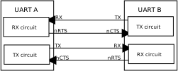
UART Auto Flow Control Signal Connection
Note
The RTS and CTS signals are active low.
RTS Signal Behavior
Device A sets its RTS signal to low when it is ready to receive data, notifying Device B that it can send data.
When the amount of data in Device A’s receive FIFO reaches the configured threshold, the RTS signal is set to high, notifying Device B to stop sending data.
When the amount of data in Device A’s receive FIFO drops back to the chip-specific threshold (see note below), the RTS signal is set to low, notifying Device B to resume data transmission.
Note
Once RTS is set to high, the timing to set RTS to low again depends on the data count in the receive FIFO.
RTL8721Dx:The RTS signal is set to low only when the receive FIFO is
completely empty.RTL8720E:The RTS signal is set to low only when the receive FIFO is
completely empty.RTL8710E:The RTS signal is set to low only when the receive FIFO is
completely empty.RTL8726E:The RTS signal is set to low only when the receive FIFO is
completely empty.RTL8713E:The RTS signal is set to low only when the receive FIFO is
completely empty.RTL8730E:The RTS signal is set to low only when the receive FIFO is
completely empty.RTL8721F:The RTS signal is set to low when the data count in the receive FIFO drops to
configured threshold - 2.RTL8720F:The RTS signal is set to low when the data count in the receive FIFO drops to
configured threshold - 2.RTL8735C:The RTS signal is set to low only when the receive FIFO is
completely empty.
CTS Signal Behavior
Device A monitors the CTS signal from Device B to determine whether to continue sending data:
When the CTS signal is low, Device A can send data.
When the CTS signal is high, Device A does not send data.
Application Examples
The SDK provides two types of functional examples to help developers understand and use UART features:
mbed Examples
Path:
{SDK}\example\peripheral\mbed\UART\{demo}Demonstrate how to implement UART control in the mbed environment.
Raw Examples
Path:
{SDK}\example\peripheral\raw\UART\{demo}Demonstrate how to directly control UART without an abstraction layer.
Below is a brief description of the functions of the raw examples:
raw_uart_poll_trx demonstrates data transmission and reception in the UART
pollingoperation mode;raw_uart_poll_autoctrl demonstrates transmission and reception of large amounts of data in UART
pollingoperation mode withauto flow control;raw_uart_int_trx demonstrates data transmission and reception in the UART
interruptoperation mode;raw_uart_int_stream demonstrates transmission and reception of large amounts of data in the UART
interruptoperation mode;raw_uart_int_rx_timeout demonstrates data transmission and reception in UART
interruptoperation mode with timeout protection;raw_uart_dma_clock demonstrates data transmission in the UART
DMAoperation mode;raw_uart_dma_stream demonstrates transmission and reception of a
fixed amountof data in the UARTDMAoperation mode;raw_uart_dma_rx_fc demonstrates reception of a
variable-lengthamount of data in the UARTDMAoperation mode.
Note
To find out which chips the examples support, check the README.md file in the example path.
Raw API
UART Exported Types
-
struct IrDA_InitTypeDef
UART IRDA Init Structure Definition.
Public Members
-
u32 UART_IrDARxInv
Specifies the uart irda rx invert control. This parameter can be ENABLE or DISABLE. ENABLE: invert the irda input signal. DISABLE: does’t invert the irda input signal. This parameter is only used in IrDA mode.
-
u32 UART_IrDATxInv
Specifies the uart irda tx invert control. This parameter can be ENABLE or DISABLE. ENABLE: invert the irda output signal. DISABLE: does’t invert the irda output signal. This parameter is only used in IrDA mode.
-
u32 UART_UpperShift
Specifies the uart irda tx pulse right edge shift direction. This parameter can be a value of UART IRDA Pulse Shift.
-
u32 UART_UpperShiftVal
Specifies the uart irda tx pulse right edge shift value in the given direction. This parameter can be a number between 0x0000 and 0x7fff.
-
u32 UART_LowShift
Specifies the uart irda tx pulse left edge shift direction. This parameter can be a value of UART IRDA Pulse Shift.
-
u32 UART_LowShiftVal
Specifies the uart irda tx pulse left edge shift value in the given direction. This parameter can be a number between 0x0000 and 0x7fff.
-
u32 UART_RxFilterThres
Specifies the uart irda rx filter threshold. This parameter can be a number between 0x0000 and 0x7fff This parameter is only used in IrDA mode.
-
u32 UART_RxFilterCmd
Specifies the uart irda rx filter control. This parameter can be ENABLE or DISABLE. ENABLE: uart IrDA rx filter is used. DISABLE: uart IrDA rx filter is not used. This parameter is only used in IrDA mode.
-
u32 UART_IrDARxInv
-
struct UART_DevTable
UART Dev Table Structure Definition.
Public Members
-
UART_TypeDef *UARTx
-
u32 Tx_HandshakeInterface
-
u32 Rx_HandshakeInterface
-
IRQn_Type IrqNum
-
UART_TypeDef *UARTx
-
struct UART_InitTypeDef
UART Init Structure Definition.
Public Members
-
u32 DmaModeCtrl
Specifies the uart DMA mode state. This parameter can be ENABLE or DISABLE.
-
u32 WordLen
Specifies the UART word length. This parameter can be a value of UART Word Length.
-
u32 StopBit
Specifies the UART stop bit number. This parameter can be a value of UART Stop Bit.
-
u32 Parity
Specifies the UART parity. This parameter can be a value of UART Parity Enable.
-
u32 ParityType
Specifies the UART parity type. This parameter can be a value of UART Parity Type.
-
u32 StickParity
Specifies the UART sticky parity. This parameter can be a value of UART Sticky Parity Type.
-
u32 FlowControl
Specifies the UART auto flow control. This parameter can be ENABLE or DISABLE.
-
u32 RxFifoTrigLevel
Specifies the UART rx fifo trigger level. This parameter can be a value of UART Rx FIFO Trigger Level.
-
u32 RxErReportCtrl
Specifies the UART rx error report control. This parameter can be a value of UART Rx Error Report.
-
u32 RxTimeOutCnt
Specifies the UART rx time out counter. This parameter can be a number between 0x00 and 0xffff.
-
u32 DmaModeCtrl
UART Exported Constants
UART IRDA Pulse Shift
/* IrDA TX pulse shift left direction. */
#define UART_IRDA_PULSE_LEFT_SHIFT ((u32)0x00000000)

/* IrDA TX pulse shift right direction. */
#define UART_IRDA_PULSE_RIGHT_SHIFT ((u32)0x00000001)

/* Check if IrDA pulse shift value is valid. */
#define IS_IRDA_PUL_SHIFT (((SHIFT) == UART_IRDA_PULSE_LEFT_SHIFT) || \
    ((SHIFT) == UART_IRDA_PULSE_RIGHT_SHIFT))
UART MAUTO FLOW CONTROL define
/* Enable UART auto flow control via AFE and RTS bits. */
#define RUART_MCL_FLOW_ENABLE ((u32)(RUART_BIT_AFE | RUART_BIT_RTS))
UART Parity Enable
/* UART parity disabled. */
#define RUART_PARITY_DISABLE ((u32)0x00000000)

/* UART parity enabled. */
#define RUART_PARITY_ENABLE ((u32)0x00000001)

/* Check if UART parity enable value is valid. */
#define IS_UART_PARITY_ENABLE (((VAL) == RUART_PARITY_DISABLE) || \
    ((VAL) == RUART_PARITY_ENABLE))
UART Parity Type
/* UART parity type: odd. */
#define RUART_ODD_PARITY ((u32)0x00000000)

/* UART parity type: even. */
#define RUART_EVEN_PARITY ((u32)0x00000001)

/* Check if UART parity type value is valid. */
#define IS_UART_PARITY_TYPE (((VAL) == RUART_ODD_PARITY) || \
    ((VAL) == RUART_EVEN_PARITY))
UART Rx Error Report
/* UART Rx error report disabled. */
#define UART_RX_ERROR_REPORT_DISABLE ((u32)0x00000000)

/* UART Rx error report enabled. */
#define UART_RX_ERROR_REPORT_ENABLE ((u32)0x00000001)

/* Check if UART Rx error report value is valid. */
#define IS_UART_RX_ERROR_REPORT (((REPORT) == UART_RX_ERROR_REPORT_DISABLE) || \
    ((REPORT) == UART_RX_ERROR_REPORT_ENABLE))
UART Rx Error Type
/* Bitmask of all Rx error flags. */
#define UART_ALL_RX_ERR (RUART_BIT_RXFIFO_ERR | \
    RUART_BIT_BREAK_INT | \
    RUART_BIT_FRM_ERR | \
    RUART_BIT_PAR_ERR | \
    RUART_BIT_OVR_ERR)
UART Rx FIFO Trigger Level
/* Rx FIFO trigger level: 1 byte. */
#define UART_RX_FIFOTRIG_LEVEL_1BYTES ((u32)0x00000000)
/* Rx FIFO trigger level: quarter full. */
#define UART_RX_FIFOTRIG_LEVEL_QUARTER ((u32)0x00000001)

/* Rx FIFO trigger level: half full. */
#define UART_RX_FIFOTRIG_LEVEL_HALF ((u32)0x00000002)

/* Rx FIFO trigger level: depth minus 2. */
#define UART_RX_FIFOTRIG_LEVEL_MINUS2 ((u32)0x00000003)
/* Rx FIFO trigger level: quarter full. */
#define UART_RX_FIFOTRIG_LEVEL_QUARTER ((u32)0x00000001)

/* Rx FIFO trigger level: half full. */
#define UART_RX_FIFOTRIG_LEVEL_HALF ((u32)0x00000002)

/* Rx FIFO trigger level: depth minus 2. */
#define UART_RX_FIFOTRIG_LEVEL_MINUS2 ((u32)0x00000003)
/* Rx FIFO trigger level: quarter full. */
#define UART_RX_FIFOTRIG_LEVEL_QUARTER ((u32)0x00000001)

/* Rx FIFO trigger level: half full. */
#define UART_RX_FIFOTRIG_LEVEL_HALF ((u32)0x00000002)

/* Rx FIFO trigger level: depth minus 2. */
#define UART_RX_FIFOTRIG_LEVEL_MINUS2 ((u32)0x00000003)
/* Rx FIFO trigger level: quarter full. */
#define UART_RX_FIFOTRIG_LEVEL_QUARTER ((u32)0x00000001)

/* Rx FIFO trigger level: half full. */
#define UART_RX_FIFOTRIG_LEVEL_HALF ((u32)0x00000002)

/* Rx FIFO trigger level: depth minus 2. */
#define UART_RX_FIFOTRIG_LEVEL_MINUS2 ((u32)0x00000003)
/* Rx FIFO trigger level: quarter full. */
#define UART_RX_FIFOTRIG_LEVEL_QUARTER ((u32)0x00000001)

/* Rx FIFO trigger level: half full. */
#define UART_RX_FIFOTRIG_LEVEL_HALF ((u32)0x00000002)

/* Rx FIFO trigger level: depth minus 2. */
#define UART_RX_FIFOTRIG_LEVEL_MINUS2 ((u32)0x00000003)
/* Rx FIFO trigger level: 16 bytes. */
#define UART_RX_FIFOTRIG_LEVEL_16BYTES ((u32)0x00000040)

/* Rx FIFO trigger level: 32 bytes. */
#define UART_RX_FIFOTRIG_LEVEL_32BYTES ((u32)0x00000080)

/* Rx FIFO trigger level: 62 bytes. */
#define UART_RX_FIFOTRIG_LEVEL_62BYTES ((u32)0x000000c0)

/* Check if UART RX FIFO trigger level is valid. */
#define IS_UART_RXFIFO_LEVEL (((LEVEL) == UART_RX_FIFOTRIG_LEVEL_1BYTES) || \
    ((LEVEL) == UART_RX_FIFOTRIG_LEVEL_16BYTES) || \
    ((LEVEL) == UART_RX_FIFOTRIG_LEVEL_32BYTES) || \
    ((LEVEL) == UART_RX_FIFOTRIG_LEVEL_62BYTES))
/* Rx FIFO trigger level: quarter full. */
#define UART_RX_FIFOTRIG_LEVEL_QUARTER ((u32)0x00000001)

/* Rx FIFO trigger level: half full. */
#define UART_RX_FIFOTRIG_LEVEL_HALF ((u32)0x00000002)

/* Rx FIFO trigger level: depth minus 2. */
#define UART_RX_FIFOTRIG_LEVEL_MINUS2 ((u32)0x00000003)
/* Rx FIFO trigger level: quarter full. */
#define UART_RX_FIFOTRIG_LEVEL_QUARTER ((u32)0x00000001)

/* Rx FIFO trigger level: half full. */
#define UART_RX_FIFOTRIG_LEVEL_HALF ((u32)0x00000002)

/* Rx FIFO trigger level: depth minus 2. */
#define UART_RX_FIFOTRIG_LEVEL_MINUS2 ((u32)0x00000003)
UART Software Status
/* TX state: DMA transfer in progress. */
#define STATETX_DMA 1

/* TX state: interrupt-driven transfer in progress. */
#define STATETX_INT 2

/* TX state: polling transfer in progress. */
#define STATETX_POLL 3

/* RX state: DMA receive in progress. */
#define STATERX_DMA 1

/* RX state: interrupt-driven receive in progress. */
#define STATERX_INT 2

/* RX state: polling receive in progress. */
#define STATERX_POLL 3
UART Sticky Parity Type
/* UART sticky parity disabled. */
#define RUART_STICK_PARITY_DISABLE ((u32)0x00000000)

/* UART sticky parity enabled. */
#define RUART_STICK_PARITY_ENABLE ((u32)0x00000001)

/* Check if UART sticky parity enable value is valid. */
#define IS_UART_STICK_PARITY_ENABLE (((VAL) == RUART_STICK_PARITY_DISABLE) || \
    ((VAL) == RUART_STICK_PARITY_ENABLE))
UART Stop Bit
/* UART stop bit: 1 stop bit. */
#define RUART_STOP_BIT_1 ((u32)0x00000000)

/* UART stop bit: 2 stop bits. */
#define RUART_STOP_BIT_2 ((u32)0x00000001)

/* Check if UART stop bit value is valid. */
#define IS_UART_STOP_BIT (((VAL) == RUART_STOP_BIT_1) || \
    ((VAL) == RUART_STOP_BIT_2))
UART Word Length
/* UART word length: 7 bits. */
#define RUART_WLS_7BITS ((u32)0x00000000)

/* UART word length: 8 bits. */
#define RUART_WLS_8BITS ((u32)0x00000001)

/* Check if UART word length value is valid. */
#define IS_UART_WLS (((VAL) == RUART_WLS_7BITS) || \
    ((VAL) == RUART_WLS_8BITS))
UART Exported Functions
-
void UART_IrDACmd(UART_TypeDef *UARTx, u32 NewState)
Enable or disable the IrDA function.
- Parameters:
UARTx – UART device pointer, which can be any UARTx_DEV defined in Peripheral Declarations.
NewState – New state of the IrDA. This parameter can be ENABLE or DISABLE.
-
void UART_IrDAInit(UART_TypeDef *UARTx, IrDA_InitTypeDef *IrDA_InitStruct)
Configure the UART’s IrDA interface.
- Parameters:
UARTx – UART device pointer, which can be any UARTx_DEV defined in Peripheral Declarations.
IrDA_InitStruct – Pointer to a IrDA_InitTypeDef structure that contains the configuration information of the IrDA module.
-
void UART_IrDAStructInit(IrDA_InitTypeDef *IrDA_InitStruct)
Fill each IrDA_InitStruct member with its default value.
- Parameters:
IrDA_InitStruct – Pointer to a IrDA_InitTypeDef structure which will be initialized.
-
void UART_LPRxBaudSet(UART_TypeDef *UARTx, u32 BaudRate, u32 RxIPClockHz)
Set UART baud rate of low power rx path.
- Parameters:
UARTx – UART device pointer, which can be any UARTx_DEV defined in Peripheral Declarations.
BaudRate – Desired baud rate.
RxIPClockHz – UART rx clock in Hz.
Note
According to the baud rate calculation formula in low power rx path, CycPerbit = round(fpclock/BaudRate)
-
void UART_MonitorParaConfig(UART_TypeDef *UARTx, u32 BitNumThres, u32 OscPerbitUpdCtrl)
Configure UART monitor parameters.
- Parameters:
UARTx – UART device pointer, which can be any UARTx_DEV defined in Peripheral Declarations.
BitNumThres – Configure bit number threshold of one monitor period.
OscPerbitUpdCtrl – OSC cycnum_perbit update bit, which can be ENABLE or DISABLE.
-
void UART_RXDMACmd(UART_TypeDef *UARTx, u32 NewState)
Enable or disable UART RX DMA.
- Parameters:
UARTx – UART device pointer, which can be any UARTx_DEV defined in Peripheral Declarations.
NewState – New state of UART RX DMA. This parameter can be ENABLE or DISABLE.
-
void UART_RXDMAConfig(UART_TypeDef *UARTx, u32 RxDmaBurstSize)
Configure UART RX DMA burst size.
- Parameters:
UARTx – UART device pointer, which can be any UARTx_DEV defined in Peripheral Declarations.
RxDmaBurstSize – UART RX DMA burst size.
Note
RxDmaBurstSize should not be more than half of rxfifo depth.
RxDmaBurstSize should not be smaller than GDMA_SrcMsize in function UART_RXGDMA_Init().
For better performance, it is suggested to make RxDmaBurstSize be equal to GDMA_SrcMsize, which is 16.
-
bool UART_RXGDMA_Init(u8 UartIndex, GDMA_InitTypeDef *GDMA_InitStruct, void *CallbackData, IRQ_FUN CallbackFunc, u8 *pRxBuf, u32 RxCount)
Initialize and enable UART RX GDMA.
- Parameters:
UartIndex – UART index, which can be 0~(MAX_UART_INDEX-1).
GDMA_InitStruct – Pointer to a GDMA_InitTypeDef structure that contains configuration information of the GDMA peripheral.
CallbackData – GDMA callback data.
CallbackFunc – GDMA callback function.
pRxBuf – Pointer to rx buffer.
RxCount – Rx count, 0 means using UART as DMA flow controller.
- Returns:
TRUE or FALSE.
-
void UART_RxDebounceCmd(UART_TypeDef *UARTx, u32 NewState)
Enable or disable the rx debounce function.
- Parameters:
UARTx – UART device pointer, which can be any UARTx_DEV defined in Peripheral Declarations.
NewState – New state of rx debounce function. This parameter can be ENABLE or DISABLE.
-
void UART_RxDebounceConfig(UART_TypeDef *UARTx, u32 RxDebounceCycle)
Configure UART RX Debounce Cycle.
- Parameters:
UARTx – UART device pointer, which can be any UARTx_DEV defined in Peripheral Declarations.
RxDebounceCycle – UART RX Debounce Cycle.
Note
unit is cycle of sclk.
-
u32 UART_RxMonBaudCtrlRegGet(UART_TypeDef *UARTx)
Get the Monitor Baud Rate control register value of the Low Power Rx Path.
- Parameters:
UARTx – UART device pointer, which can be any UARTx_DEV defined in Peripheral Declarations.
- Returns:
The value of the MON_BAUD_CTRL register.
Note
MON_BAUD_CTRL[28:9] field value is the monitor result under OSC 2M Hz Clock.
-
void UART_RxMonitorCmd(UART_TypeDef *UARTx, u32 NewState)
Enable or disable the monitor function in Low Power Rx Path.
- Parameters:
UARTx – UART device pointer, which can be any UARTx_DEV defined in Peripheral Declarations.
NewState – New state of monitoring. This parameter can be ENABLE or DISABLE.
-
u32 UART_RxMonitorSatusGet(UART_TypeDef *UARTx)
Get the status of the Low Power Rx Monitoring.
- Parameters:
UARTx – UART device pointer, which can be any UARTx_DEV defined in Peripheral Declarations.
- Returns:
The value of the REG_MON_BAUD_STS register.
Note
Read this register can clear the monitor interrupt status. Besides, REG_MON_BAUD_STS[19:0] field value is the monitor result under XTAL 2M Hz Clock.
-
void UART_TXDMACmd(UART_TypeDef *UARTx, u32 NewState)
Enable or disable UART TX DMA.
- Parameters:
UARTx – UART device pointer, which can be any UARTx_DEV defined in Peripheral Declarations.
NewState – New state of UART TX DMA. This parameter can be ENABLE or DISABLE.
-
void UART_TXDMAConfig(UART_TypeDef *UARTx, u32 TxDmaBurstSize)
Configure UART TX DMA burst size.
- Parameters:
UARTx – UART device pointer, which can be any UARTx_DEV defined in Peripheral Declarations.
TxDmaBurstSize – UART TX DMA burst size.
Note
TxDmaBurstSize should not be smaller than GDMA_DstMsize in function UART_TXGDMA_Init().
For better performance, it is suggested to make TxDmaBurstSize be equal to GDMA_DstMsize, which is 4.
-
bool UART_TXGDMA_Init(u8 UartIndex, GDMA_InitTypeDef *GDMA_InitStruct, void *CallbackData, IRQ_FUN CallbackFunc, u8 *pTxBuf, u32 TxCount)
Initialize and enable UART TX GDMA.
- Parameters:
UartIndex – UART index, which can be 0~(MAX_UART_INDEX-1).
GDMA_InitStruct – Pointer to a GDMA_InitTypeDef structure that contains configuration information of the GDMA peripheral.
CallbackData – GDMA callback data.
CallbackFunc – GDMA callback function.
pTxBuf – Pointer to tx buffer.
TxCount – Tx count.
- Returns:
TRUE or FALSE.
-
void UART_RTSForceCmd(UART_TypeDef *UARTx, u32 NewState)
Force UART RTS_output to be logic 1(inactive) or logic 0(active).
- Parameters:
UARTx – UART device pointer, which can be any UARTx_DEV defined in Peripheral Declarations.
NewState –
This parameter can be one of the following values:
ENABLE: Force RTS_output to be inactive, informing peer device to stop sending data.
DISABLE: RTS_output stays active until Rx FIFO level reaches RECVTRG and becomes active again, informing peer device to continue sending data.
Note
BIT_AFE should be set to 1 when call UART_RTSForceCmd().
Not supported.
Not supported.
Not supported.
Not supported.
Not supported.
-
void UART_REToThreConfig(UART_TypeDef *UARTx, u32 RxTimeout)
Configure UART rxfifo empty timeout threshold.
- Parameters:
UARTx – UART device pointer, which can be any UARTx_DEV defined in Peripheral Declarations.
RxTimeout – Rx timeout counter works in uart_rclk.
FUNCTION_REF=UART_RTSForceCmd
-
void UART_RxToThreConfig(UART_TypeDef *UARTx, u32 RxTimeout)
Configure UART rx timeout threshold.
- Parameters:
UARTx – UART device pointer, which can be any UARTx_DEV defined in Peripheral Declarations.
RxTimeout – Rx timeout value, unit is one bit time.
FUNCTION_REF=UART_RTSForceCmd
-
void UART_RxMaxLenConfig(UART_TypeDef *UARTx, u32 RxMaxLen)
Configure UART rx dma max length.
- Parameters:
UARTx – UART device pointer, which can be any UARTx_DEV defined in Peripheral Declarations.
RxMaxLen – Rx DMA max len, unit is one byte.
Note
It only works when UART acts as RX DMA flow controller.
FUNCTION_REF=UART_RxToThreConfig
UART Normal Functions
-
void UART_BaudParaGet(u32 baudrate, u32 *ovsr, u32 *ovsr_adj)
Get ovsr & ovsr_adj parameters according to the given baudrate.
- Parameters:
baudrate – Desired baudrate in bps.
ovsr – Pointer to ovsr parameter.
ovsr_adj – Pointer to ovsr_adj parameter.
-
void UART_BaudParaGetFull(u32 IPclk, u32 baudrate, u32 *ovsr, u32 *ovsr_adj)
Get ovsr & ovsr_adj parameters according to the given baudrate and UART IP clock.
- Parameters:
IPclk – UART IP clock in Hz.
baudrate – Desired baudrate in bps.
ovsr – Pointer to ovsr parameter.
ovsr_adj – Pointer to ovsr_adj parameter.
-
void UART_BreakCtl(UART_TypeDef *UARTx, u32 NewState)
Enable or disable UART break control function.
- Parameters:
UARTx – UART device pointer, which can be any UARTx_DEV defined in Peripheral Declarations.
NewState – New state of UART Break Signal. This parameter can be ENABLE or DISABLE.
-
void UART_CharGet(UART_TypeDef *UARTx, u8 *pRxByte)
Receive single data from UART rx FIFO.
- Parameters:
UARTx – UART device pointer, which can be any UARTx_DEV defined in Peripheral Declarations.
pRxByte – Pointer to received data.
-
void UART_CharPut(UART_TypeDef *UARTx, u8 TxData)
Transmit single data to UART tx FIFO.
- Parameters:
UARTx – UART device pointer, which can be any UARTx_DEV defined in Peripheral Declarations.
TxData – Data to be transmitted.
-
u32 UART_ClearRxFifo(UART_TypeDef *UARTx)
Clear Rx FIFO.
- Parameters:
UARTx – UART device pointer, which can be any UARTx_DEV defined in Peripheral Declarations.
- Returns:
Rx FIFO is empty or not, which can be a value of:
TRUE: Rx FIFO is cleared.
FALSE: Rx FIFO is not cleared.
-
void UART_ClearTxFifo(UART_TypeDef *UARTx)
Clear Tx FIFO.
- Parameters:
UARTx – UART device pointer, which can be any UARTx_DEV defined in Peripheral Declarations.
-
void UART_DeInit(UART_TypeDef *UARTx)
Deinitialize the UARTx peripheral registers to their default reset values.
- Parameters:
UARTx – UART device pointer, which can be any UARTx_DEV defined in Peripheral Declarations.
-
void UART_INTConfig(UART_TypeDef *UARTx, u32 UART_IT, u32 newState)
Enable or disable specified UARTx interrupt(s).
- Parameters:
UARTx – UART device pointer, which can be any UARTx_DEV defined in Peripheral Declarations.
UART_IT – Specified UARTx interrupt sources to be enabled or disabled. This parameter can be one or a combination of IER register bits.
newState – New state of the specified UARTx interrupts. This parameter can be ENABLE or DISABLE.
-
void UART_INT_Clear(UART_TypeDef *UARTx, u32 UART_IT)
Clear specified UARTx interrupt status.
- Parameters:
UARTx – UART device pointer, which can be any UARTx_DEV defined in Peripheral Declarations.
UART_IT – Specified UARTx interrupt sources to be clear. This parameter can be one or a combination of ICR register bits.
-
void UART_Init(UART_TypeDef *UARTx, UART_InitTypeDef *UART_InitStruct)
Initialize the UARTx peripheral according to the specified parameters in the UART_InitStruct.
- Parameters:
UARTx – UART device pointer, which can be any UARTx_DEV defined in Peripheral Declarations.
UART_InitStruct – Pointer to a UART_InitTypeDef structure that contains the configuration information of the specified UART peripheral.
-
u32 UART_IntStatus(UART_TypeDef *UARTx)
Get the interrupt identification register value.
- Parameters:
UARTx – UART device pointer, which can be any UARTx_DEV defined in Peripheral Declarations.
- Returns:
The interrupt identification register value.
-
u32 UART_LineStatusGet(UART_TypeDef *UARTx)
Get the Line status register value.
- Parameters:
UARTx – UART device pointer, which can be any UARTx_DEV defined in Peripheral Declarations.
- Returns:
The Line status register value.
-
u32 UART_ModemStatusGet(UART_TypeDef *UARTx)
Get the modem status register value.
- Parameters:
UARTx – UART device pointer, which can be any UARTx_DEV defined in Peripheral Declarations.
- Returns:
The modem status register value.
-
u32 UART_Readable(UART_TypeDef *UARTx)
Check if there is data in rx FIFO.
- Parameters:
UARTx – UART device pointer, which can be any UARTx_DEV defined in Peripheral Declarations.
- Returns:
Status value, which can be one of the following values:
1: Rx FIFO has valid data and data can be read from rx FIFO.
0: Rx FIFO is empty.
-
void UART_ReceiveData(UART_TypeDef *UARTx, u8 *OutBuf, u32 Count)
Receive data from rx FIFO to given buffer.
- Parameters:
UARTx – UART device pointer, which can be any UARTx_DEV defined in Peripheral Declarations.
OutBuf – Pointer to buffer to save data read from UART FIFO.
Count – Number of data to be read.
-
u32 UART_ReceiveDataTO(UART_TypeDef *UARTx, u8 *OutBuf, u32 Count, u32 Times)
Receive data from rx FIFO before timeout.
- Parameters:
UARTx – UART device pointer, which can be any UARTx_DEV defined in Peripheral Declarations.
OutBuf – Pointer to buffer to save data read from UART FIFO.
Count – Number of data to be read.
Times – Polling times before timeout.
- Returns:
Received data length.
-
void UART_RxByteCntClear(UART_TypeDef *UARTx)
Clear Rx Byte Counter.
- Parameters:
UARTx – UART device pointer, which can be any UARTx_DEV defined in Peripheral Declarations.
Note
Clear Rx Byte Counter(REG_RX_BYTE_CNT[15:0]) by writing 1 to clr_rx_byte_cnt(REG_RX_BYTE_CNT[16]).
-
u32 UART_RxByteCntGet(UART_TypeDef *UARTx)
Get Rx Byte Counter Value.
- Parameters:
UARTx – UART device pointer, which can be any UARTx_DEV defined in Peripheral Declarations.
- Returns:
The value of Rx Byte Counter.
Note
This counter will be increased by 1 each time reading rx FIFO, no matter rx FIFO is empty or not.
-
void UART_RxCmd(UART_TypeDef *UARTx, u32 NewState)
Enable or disable UART high rate rx path.
- Parameters:
UARTx – UART device pointer, which can be any UARTx_DEV defined in Peripheral Declarations.
NewState – New state of the Rx Path. This parameter can be ENABLE or DISABLE.
Note
Because the TX/RX of the IrDA transceiver are in the same module, RX FIFO can also receive available data when in the process of TX. Therefore, the RX Path must be disabled when TX is going on. Namely, IrDA must work in the Half duplex mode, though normal UART IP supports Full duplex.
-
void UART_SendData(UART_TypeDef *UARTx, u8 *InBuf, u32 Count)
Transmit data to tx FIFO with polling UART writable status.
- Parameters:
UARTx – UART device pointer, which can be any UARTx_DEV defined in Peripheral Declarations.
InBuf – Pointer to buffer to be written to Tx FIFO.
Count – Number of data to be written.
-
u32 UART_SendDataTO(UART_TypeDef *UARTx, u8 *InBuf, u32 Count, u32 Times)
Transmit data to tx FIFO before timeout.
- Parameters:
UARTx – UART device pointer, which can be any UARTx_DEV defined in Peripheral Declarations.
InBuf – Pointer to buffer to be written to Tx FIFO.
Count – Number of data to be written.
Times – Polling times before timeout.
- Returns:
Transmitted data length.
-
void UART_SetBaud(UART_TypeDef *UARTx, u32 BaudRate)
Set UART baudrate according to given baudrate.
- Parameters:
UARTx – UART device pointer, which can be any UARTx_DEV defined in Peripheral Declarations.
BaudRate – Desired baudrate in bps.
-
void UART_SetBaudExt(UART_TypeDef *UARTx, u32 Ovsr, u32 Ovsr_adj)
Set UART baudrate according to given baudrate parameter Ovsr & Ovsr_adj.
- Parameters:
UARTx – UART device pointer, which can be any UARTx_DEV defined in Peripheral Declarations.
Ovsr – Ovsr parameter, which is related with integer part. This parameter is calculated with UART IP clock and desired baudrate.
Ovsr_adj – Ovsr_adj parameter, which is related with fractional part. This parameter is also calculated with UART IP clock and desired baudrate.
-
void UART_SetRxLevel(UART_TypeDef *UARTx, u32 FifoLv)
Set UART RX FIFO level to trigger RX interrupt/RTS de-assert.
- Parameters:
UARTx – UART device pointer, which can be any UARTx_DEV defined in Peripheral Declarations.
FifoLv – RX FIFO trigger level, this parameter can be one of the values in UART Rx FIFO Trigger Level.
-
void UART_StructInit(UART_InitTypeDef *UART_InitStruct)
Fill each UART_InitStruct member with its default value.
- Parameters:
UART_InitStruct – Pointer to a UART_InitTypeDef structure which will be initialized.
-
void UART_WaitBusy(UART_TypeDef *UARTx, u32 PollTimes)
Wait until uart tx completes.
- Parameters:
UARTx – UART device pointer, which can be any UARTx_DEV defined in Peripheral Declarations.
PollTimes – Polling times before exiting.
-
u32 UART_Writable(UART_TypeDef *UARTx)
Check if tx FIFO is writable.
- Parameters:
UARTx – UART device pointer, which can be any UARTx_DEV defined in Peripheral Declarations.
- Returns:
Status value, which can be one of the following values:
1: Tx FIFO is not full and writing data to tx FIFO is ok.
0: Tx FIFO is full.
Mbed API
MBED_UART Exported Types
Enumeration Type
-
enum FlowControl
UART FlowControl mode used by serial_set_flow_control.
Values:
/* No RTS/CTS. */
FlowControlNone

/* RTS enable. */
FlowControlRTS

/* CTS enable. */
FlowControlCTS

/* RTS/CTS enable. */
FlowControlRTSCTS
-
enum SerialFifoLevel
Define RX FIFO Level: RX interrupt trigger, RTS de-assert trigger.
Values:
/* RX FIFO trigger level at 1 byte. */
FifoLv1Byte = 0

/* RX FIFO trigger level at quarter full. */
FifoLvQuarter = 1

/* RX FIFO trigger level at half full. */
FifoLvHalf = 2

/* RX FIFO trigger level at nearly full. */
FifoLvFull = 3
-
enum SerialIrq
UART Interrupt enable/disable used by serial_irq_set.
Values:
/* RX IRQ enable/disable. */
RxIrq

/* TX IRQ enable/disable. */
TxIrq
-
enum SerialParity
UART Parity mode used by serial_format.
Values:
/* Parity disable. */
ParityNone = 0

/* Odd parity enable. */
ParityOdd = 1

/* Even parity enable. */
ParityEven = 2

/* Sticky parity 1 enable. */
ParityForced1 = 3

/* Sticky parity 0 enable. */
ParityForced0 = 4
Structure Type
-
typedef struct serial_s serial_t
Serial object type, defined as struct serial_s.
MBED_UART Exported Functions
-
void serial_baud(serial_t *obj, int baudrate)
Set UART device baudrate.
- Parameters:
obj – UART object defined in application software.
baudrate – Baud Rate in units of bps, e.g. 115200.
-
void serial_break_clear(serial_t *obj)
Disable UART break control function.
- Parameters:
obj – UART object defined in application software.
-
void serial_break_set(serial_t *obj)
Enable UART break control function.
- Parameters:
obj – UART object defined in application software.
-
void serial_clear(serial_t *obj)
Clear UART Rx FIFO.
- Parameters:
obj – UART object defined in application software.
-
void serial_clear_rx(serial_t *obj)
Clear UART Rx FIFO.
- Parameters:
obj – UART object defined in application software.
-
void serial_clear_tx(serial_t *obj)
Clear UART Tx FIFO.
- Parameters:
obj – UART object defined in application software.
-
void serial_disable(serial_t *obj)
Disable UART clock and function.
- Parameters:
obj – UART object defined in application software.
-
void serial_enable(serial_t *obj)
Enable UART clock and function.
- Parameters:
obj – UART object defined in application software.
-
void serial_format(serial_t *obj, int data_bits, SerialParity parity, int stop_bits)
Set UART format.
- Parameters:
obj – UART object defined in application software.
data_bits –
Data bits, this parameter can be one of the following values:
7
8
parity –
Parity type, this parameter can be one of the following values:
ParityNone
ParityOdd
ParityEven
ParityForced1
ParityForced0
stop_bits –
Stop bit, this parameter can be one of the following values:
2
1
-
void serial_free(serial_t *obj)
Deinitialize the UART device, including clock, function, interrupt and UART registers.
- Parameters:
obj – UART object defined in application software.
-
int serial_getc(serial_t *obj)
Get one byte data through UART.
- Parameters:
obj – UART object defined in application software.
- Returns:
Received character.
Note
This function is a synchronous, blocking API.
-
void serial_init(serial_t *obj, PinName tx, PinName rx)
Initialize the UART device, including clock, function, interrupt and UART registers.
- Parameters:
obj – UART object defined in application software.
tx – Tx PinName according to pinmux spec.
rx – Rx PinName according to pinmux spec.
-
void serial_irq_handler(serial_t *obj, uart_irq_handler handler, uint32_t id)
Register UART interrupt handler if needed.
- Parameters:
obj – UART object defined in application software.
handler – UART interrupt callback function.
id – UART interrupt callback parameter.
-
void serial_irq_set(serial_t *obj, SerialIrq irq, uint32_t enable)
Configure UART interrupt.
- Parameters:
obj – UART object defined in application software.
irq –
Tx or Rx interrupt, this parameter can be one of the following values:
RxIrq
TxIrq
enable –
This parameter can be one of the following values:
0: Disable specified irq handler.
1: Enable specified irq handler.
-
void serial_putc(serial_t *obj, int c)
Send one byte data through UART.
- Parameters:
obj – UART object defined in application software.
c – Data to be transmitted.
Note
This function is a synchronous, blocking API.
-
int serial_readable(serial_t *obj)
Check if there is data in UART Rx FIFO.
- Parameters:
obj – UART object defined in application software.
- Returns:
Check result, which can be a value of the followings:
1: There is data in Rx FIFO.
0: There is no data in Rx FIFO.
-
int32_t serial_recv_blocked(serial_t *obj, char *prxbuf, uint32_t len, uint32_t timeout_ms)
Receive data of target length under polling mode before timeout.
- Parameters:
obj – UART object defined in application software.
prxbuf – Pointer to the buffer that saves data read from UART FIFO.
len – Number of data to be received.
timeout_ms – Polling time before timeout in units of ms.
- Returns:
Bytes of received data.
Note
This function is synchronous API.
-
void serial_recv_comp_handler(serial_t *obj, void *handler, uint32_t id)
Register UART Rx complete handler.
- Parameters:
obj – UART object defined in application software.
handler – UART Rx complete callback function.
id – UART Rx complete callback parameter.
Note
This function is called when asynchronous API is used.
-
int32_t serial_recv_stream(serial_t *obj, char *prxbuf, uint32_t len)
Receive data of target length under interrupt mode.
- Parameters:
obj – UART object defined in application software.
prxbuf – Pointer to the buffer that saves data read from UART FIFO.
len – Number of data to be read.
- Returns:
HAL status, which can be a value of the followings:
HAL_OK(0): Success.
HAL_BUSY(1): Error.
Note
This function is asynchronous API.
-
int32_t serial_recv_stream_abort(serial_t *obj)
Stop the stream or stream_dma RX.
- Parameters:
obj – UART object defined in application software.
- Returns:
Number of Bytes received before stop.
-
int32_t serial_recv_stream_dma(serial_t *obj, char *prxbuf, uint32_t len)
Receive data of target length under DMA mode.
- Parameters:
obj – UART object defined in application software.
prxbuf – Pointer to the buffer that saves data read from UART FIFO.
len – Number of data to be read.
- Returns:
HAL status, which can be a value of the followings:
HAL_OK(0): Success.
HAL_BUSY(1): Error.
Note
This function is asynchronous API.
-
int32_t serial_recv_stream_dma_timeout(serial_t *obj, char *prxbuf, uint32_t len, uint32_t timeout_ms, void *force_cs)
Receive data under DMA mode before hardware timeout and UART is flow controller.
- Parameters:
obj – UART object defined in application software.
prxbuf – Pointer to the buffer that saves data read from UART FIFO.
len – Maximum received data length before timeout, or unused on platforms where data reception length is determined by hardware timeout only.
timeout_ms – Hardware timeout in ms for Rx.
force_cs – Not used, reserved for compatibility.
- Returns:
HAL status, which can be a value of the followings:
HAL_OK(0): Success.
HAL_BUSY(1): Error.
Note
This function is asynchronous API.
-
int32_t serial_recv_stream_timeout(serial_t *obj, char *prxbuf, uint32_t len, uint32_t timeout_ms, void *force_cs)
Receive data of target length under interrupt mode before timeout.
- Parameters:
obj – UART object defined in application software.
prxbuf – Pointer to the buffer that saves data read from UART FIFO.
len – Number of data to be received.
timeout_ms – Polling time before timeout.
force_cs – Forcing context switch function.
- Returns:
Bytes of data received before timeout if success or -1 if error happens.
Note
This function is a synchronous, blocking API.
-
void serial_rx_fifo_level(serial_t *obj, SerialFifoLevel FifoLv)
Set UART Rx FIFO trigger level.
- Parameters:
obj – UART object defined in application software.
FifoLv – FIFO level enum index.
-
int32_t serial_send_blocked(serial_t *obj, char *ptxbuf, uint32_t len, uint32_t timeout_ms)
Send data of target length under polling mode before timeout.
- Parameters:
obj – UART object defined in application software.
ptxbuf – Pointer to the buffer that saves data to be written to Tx FIFO.
len – Number of data to be sent.
timeout_ms – Polling time before timeout.
- Returns:
Bytes of transmitted data.
Note
This function is synchronous API.
-
void serial_send_comp_handler(serial_t *obj, void *handler, uint32_t id)
Register UART Tx complete handler.
- Parameters:
obj – UART object defined in application software.
handler – UART Tx complete callback function.
id – UART Tx complete callback parameter.
Note
This function is called when asynchronous API is used.
-
int32_t serial_send_stream(serial_t *obj, char *ptxbuf, uint32_t len)
Send data of target length under interrupt mode.
- Parameters:
obj – UART object defined in application software.
ptxbuf – Pointer to the buffer that saves data to be written to Tx FIFO.
len – Number of data to be sent.
- Returns:
HAL status, which can be a value of the followings:
HAL_OK(0): Success.
HAL_BUSY(1): Error.
Note
This function is asynchronous API.
-
int32_t serial_send_stream_abort(serial_t *obj)
Stop the stream or stream_dma TX.
- Parameters:
obj – UART object defined in application software.
- Returns:
Number of Bytes sent before stop if UART is in Tx state or HAL_OK(0) if not.
-
int32_t serial_send_stream_dma(serial_t *obj, char *ptxbuf, uint32_t len)
Send data of target length under DMA mode.
- Parameters:
obj – UART object defined in application software.
ptxbuf – Pointer to the buffer that saves data to be written to Tx FIFO.
len – Number of data to be sent.
- Returns:
HAL status, which can be a value of the followings:
HAL_OK(0): Success.
HAL_BUSY(1): Error.
Note
This function is asynchronous API.
-
void serial_set_flow_control(serial_t *obj, FlowControl type, PinName rxflow, PinName txflow)
Set UART auto flow control.
- Parameters:
obj – UART object defined in application software.
type – Auto flow control type.
rxflow – RTS pin.
txflow – CTS pin.
-
int serial_writable(serial_t *obj)
Check whether it is permitted to write data to UART Tx FIFO.
- Parameters:
obj – UART object defined in application software.
- Returns:
Check result, which can be a value of the followings:
1: It is ok to write data to Tx FIFO.
0: It is not ok to write data to Tx FIFO.
Troubleshooting
Data Loss on Wakeup via UART
Phenomenon |
Data sent to the UART to wake up the system results in some data loss after waking up. |
Cause |
The UART receive FIFO has limited size. When sent data is too long, the system cannot process it in time, resulting in only part of the data being retained. |
Solution |
|
Out-of-Bounds Data Reception with UART DMA
Phenomenon |
On RTL8721Dx/RTL8720E/RTL8710E/RTL8726E/RTL8713E/RTL8730E, received data exceeds the predefined buffer limits when running the raw_uart_dma_rx_fc example. |
Cause |
The amount of received data cannot be controlled when UART performs as DMA rx flow controller. |
Solution |
Run the raw_uart_dma_stream example and enable the definition of macro UART_USE_GTIMER_TO. This allows developers to receive no more than a specified amount of data under continuous reception. |

