Light Emitting Diode Controller (LEDC)
Supported ICs[ RTL8721Dx ][ RTL8720E ][ RTL8710E ][ RTL8726E ][ RTL8713E ][ RTL8730E ]
Introduction
LEDC (LED Controller) is a highly efficient embedded solution that supports the control of smart LED lights (such as WS2812B) and is compatible with the DSHOT protocol to drive brushless motors.
Features
Configurable data transmission pulse time and non-data period
Configurable RGB888 display mode and LED refresh time
Supports up to 8192 data sequence entries
Supports up to 1024 LEDs
Supports DMA transmission
Working Principle
Logical 0/1 Encoding and Configuration Guide
Logical “0” and “1” Encoding
Logical “0” (referred to as “Code 0”) and logical “1” (referred to as “Code 1”) are composed of high and low levels, as shown in the figure.
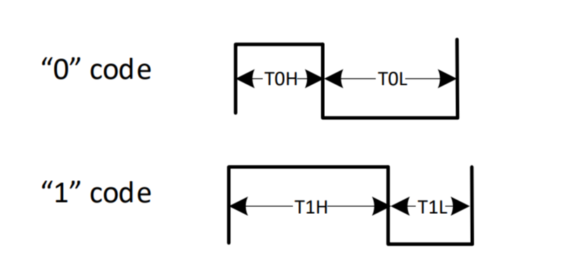
Input Code Timing
Logic Level Timing
The high and low level duration of Code 0 and Code 1 varies among different devices.
Taking the WS2812B-2020 smart LED as an example:
code0_code1_timing Code
Description
Time Range
Unit
T0H
Code 0, High Level Time
220 ~ 380
ns
T0L
Code 0, Low Level Time
580 ~ 1000
ns
T1H
Code 1, High Level Time
580 ~ 1000
ns
T1L
Code 1, Low Level Time
220 ~ 420
ns
RESET
Frame reset, Low Level time
> 280
μs
Encoding total time:
Code 0: 800ns ~ 1380ns
Code 1: 800ns ~ 1420ns
Encoding Time Configuration
By adjusting the
TxH_CNTandTxL_CNTparameters in the register, you can flexibly set the clock cycle number for the high and low levels of Code 0 and Code 1.x: Refers to 0 or 1
Count clock: XTAL40MHz
Data Transmission Timing
LED Communication Mode
Taking WS2812B LED as an example, it uses the single-wire non-return-to-zero (NRZ) communication protocol and adopts a cascade method for data transmission:
Power-on reset: After power-on, the LED receives data from the controller through the DI port. The first LED will capture and latch the first 24-bit data.
Data passing: The remaining data is transmitted to the next LED through the internal reshaping circuit from the DO port.
Signal decrement: With each LED, the signal will be reduced by 24 bits of data.
LEDC Transmission Timing
The data timing sent by LEDC to the first LED is as follows:
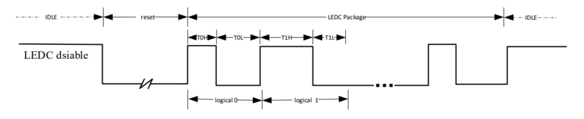
LEDC Data Transmission Timing
Reset Signal: Configurable period used to refresh the LED.
Interval Adjustment:
Supports insertion of low-level intervals between adjacent pixels
Supports insertion of low-level intervals between adjacent frames
Number of LEDs
The formula to calculate the number of supported LEDs is:
LED_NUM = (1 / LED refresh rate (frame/s) - 280 μs) / ((logical 0 or 1 coding time) * 24)
Using the timing of Code 0 and Code 1 from table code0_code1_timing as an example, the number of supported LEDs is calculated as follows:
When the LED refresh rate is 30 frames per second, the number of supported LEDs is 681 ~ 1023.
When the LED refresh rate is 60 frames per second, the number of supported LEDs is 337 ~ 853.
Application Example
raw_ledc_ws2812 demonstrates how to configure and control multiple LED lights using the LEDC module.
Note
To see the chips supported by the example, check the README.md file in the example path.
Raw API
LEDC Exported Types
-
struct LEDC_InitTypeDef
LEDC Init Structure Definition.
Public Members
-
u32 led_count
Number of external LED lamps connected. This parameter can be a value of LEDC LED Number.
-
u32 data_length
Total transfer data length in 32-bit units. This parameter can be a value of LEDC Data Length.
-
u32 t1h_ns
Logical “1” high level cycle count.
-
u32 t1l_ns
Logical “1” low level cycle count.
-
u32 t0h_ns
Logical “0” high level cycle count.
-
u32 t0l_ns
Logical “0” low level cycle count.
-
u32 reset_ns
LED reset signal cycle count N. This parameter can be a value of LEDC Reset Count.
-
u32 wait_data_time_ns
FIFO data wait timeout cycle count N. This parameter can be a value of LEDC Wait Data Time Count.
-
u32 wait_time0_en
Enable or disable wait time0 insertion between two LED data packets. This parameter can be: ENABLE or DISABLE.
-
u32 wait_time1_en
Enable or disable wait time1 insertion between two LED frame data. This parameter can be: ENABLE or DISABLE.
-
u32 wait_time0_ns
Wait time0 between two LED data packets, cycle count N. This parameter can be a value of LEDC Wait Time0 Count.
-
u32 wait_time1_ns
Wait time1 between two LED frame data, cycle count N. This parameter can be a value of LEDC Wait Time1 Count.
-
u32 output_RGB_mode
RGB byte output order. This parameter can be a value of LEDC RGB Mode.
-
u32 ledc_polarity
Output signal idle level. This parameter can be a value of LEDC Idle Level.
-
u32 ledc_trans_mode
Data transfer mode (CPU or DMA). This parameter can be a value of LEDC Transfer Mode.
-
u32 ledc_fifo_level
FIFO trigger level threshold (0 to 31). A DMA or CPU request is generated when the remaining FIFO space exceeds this value. This parameter can be a value of LEDC FIFO Level.
-
u32 led_count
LEDC Exported Constants
LEDC Data Length
/* Maximum LEDC transfer data length (8192 entries). */
#define LEDC_MAX_DATA_LENGTH (0x2000)

/* Checks if the data length parameter is within valid range. */
#define IS_LEDC_DATA_LENGTH ((LENGTH > 0) && ((LENGTH) <= LEDC_MAX_DATA_LENGTH))
LEDC FIFO Level
/* LEDC internal FIFO total depth (32 entries). */
#define LEDC_FIFO_DEPTH (32)

/* Default LEDC FIFO trigger level for DMA/CPU requests. */
#define LEDC_DEFAULT_FIFO_TRIG_LEVEL (15)
LEDC Idle Level
/* LEDC output idle level is low. */
#define LEDC_IDLE_POLARITY_LOW (0)

/* LEDC output idle level is high. */
#define LEDC_IDLE_POLARITY_HIGH (1)
LEDC Input Order
/* LEDC input data bit order: LSB first. */
#define LEDC_INPUT_LSB (0)

/* LEDC input data bit order: MSB first. */
#define LEDC_INPUT_MSB (1)

/* Checks if the input bit order parameter is valid. */
#define IS_LEDC_INPUT_ORDER ((ORDER) == LEDC_INPUT_LSB || \
    (ORDER) == LEDC_INPUT_MSB)
LEDC Interrupt
/* Bitmask for all LEDC interrupt sources. */
#define LEDC_INT_ALL ((u32)0x0000001F)

/* Bitmask for all externally-enabled LEDC interrupt sources. */
#define LEDC_INT_EXT_EN ((u32)0x0000001D)

/* Checks if the interrupt parameter is within valid range. */
#define IS_LEDC_INTERRUPT ((INT) <= LEDC_INT_ALL)
LEDC LED Number
/* Default number of LEDs connected to LEDC. */
#define LEDC_DEFAULT_LED_NUM (32)

/* Maximum number of LEDs supported by LEDC (1024). */
#define LEDC_MAX_LED_NUM (1024)

/* Checks if the LED number parameter is within valid range. */
#define IS_LEDC_LED_NUM ((NUM > 0) && (NUM <= LEDC_MAX_LED_NUM))
LEDC Output Order
/* Bitmask for the LEDC output byte order field. */
#define LEDC_OUTPUT_ORDER_MASK ((u32)0x0000001C)

/* Sets the LEDC output byte order field value. */
#define LEDC_OUTPUT_ORDER ((u32)((x) & 0x00000007) << 2)
LEDC RGB Mode
/* LEDC RGB output order: GRB. */
#define LEDC_OUTPUT_GRB (0)

/* LEDC RGB output order: GBR. */
#define LEDC_OUTPUT_GBR (1)

/* LEDC RGB output order: RGB. */
#define LEDC_OUTPUT_RGB (2)

/* LEDC RGB output order: BGR. */
#define LEDC_OUTPUT_BGR (3)

/* LEDC RGB output order: RBG. */
#define LEDC_OUTPUT_RBG (4)

/* LEDC RGB output order: BRG. */
#define LEDC_OUTPUT_BRG (5)

/* Checks if the RGB output mode parameter is valid. */
#define IS_LEDC_OUTPUT_MODE ((MODE) == LEDC_OUTPUT_GRB || \
    (MODE) == LEDC_OUTPUT_GBR || \
    (MODE) == LEDC_OUTPUT_RGB || \
    (MODE) == LEDC_OUTPUT_BGR || \
    (MODE) == LEDC_OUTPUT_RBG || \
    (MODE) == LEDC_OUTPUT_BRG)
LEDC Reset Count
/* Minimum LEDC LED reset count value (0). */
#define LEDC_MIN_RESET_CNT ((u32)0)

/* Maximum LEDC LED reset count value (0x3FFF). */
#define LEDC_MAX_RESET_CNT ((u32)0x3FFF)

/* Checks if the reset count value is within valid range. */
#define IS_LEDC_RESET_VAL ((NUM) <= LEDC_MAX_RESET_CNT)
LEDC Transfer Mode
/* LEDC CPU transfer mode. */
#define LEDC_CPU_MODE (0)

/* LEDC DMA transfer mode. */
#define LEDC_DMA_MODE (1)

/* Checks if the transfer mode parameter is valid. */
#define IS_LEDC_TRANS_MODE (((MODE) == LEDC_CPU_MODE ||\
    (MODE) == LEDC_DMA_MODE))
LEDC Wait Data Time Count
/* Minimum LEDC wait-data timeout count value (0). */
#define LEDC_MIN_WAIT_DATA_TIME_CNT ((u32)0)

/* Maximum LEDC wait-data timeout count value (0x7FFF). */
#define LEDC_MAX_WAIT_DATA_TIME_CNT ((u32)0x7FFF)

/* Checks if the wait-data time count is within valid range. */
#define IS_LEDC_WAIT_DATA_TIME_VAL ((NUM) <= LEDC_MAX_WAIT_DATA_TIME_CNT)
LEDC Wait Time0 Count
/* Minimum LEDC wait time0 count value (0). */
#define LEDC_MIN_WAIT_TIME0_CNT ((u32)0)

/* Maximum LEDC wait time0 count value (0x1FF). */
#define LEDC_MAX_WAIT_TIME0_CNT ((u32)0x1FF)

/* Checks if the wait time0 count is within valid range. */
#define IS_LEDC_WAIT_TIME0_VAL ((NUM) <= LEDC_MAX_WAIT_TIME0_CNT)
LEDC Wait Time1 Count
/* Minimum LEDC wait time1 count value (0). */
#define LEDC_MIN_WAIT_TIME1_CNT ((u32)0)

/* Maximum LEDC wait time1 count value (0x7FFFFFFF). */
#define LEDC_MAX_WAIT_TIME1_CNT ((u32)0x7FFFFFFF)

/* Checks if the wait time1 count is within valid range. */
#define IS_LEDC_WAIT_TIME1_VAL ((NUM) <= LEDC_MAX_WAIT_TIME1_CNT)
LEDC Exported Functions
-
void LEDC_ClearINT(LEDC_TypeDef *LEDCx, u32 LEDC_IT)
Clear the LEDC’s interrupt bits.
- Parameters:
LEDCx – Selected LEDC peripheral.
LEDC_IT –
Specifies the LEDCx interrupt sources to be cleared. This parameter can be one or combinations of the following values:
BIT_LEDC_FIFO_OVERFLOW_INT_EN: LEDC FIFO Overflow Interrupt
BIT_LEDC_WAITDATA_TIMEOUT_INT_EN: LEDC Wait Data Timeout Interrupt
BIT_LEDC_CPUREQ_FIFO_INT_EN: LEDC CPU Request Interrupt
BIT_LEDC_TRANS_FINISH_INT_EN: LEDC Transfer Finish Interrupt
-
void LEDC_Cmd(LEDC_TypeDef *LEDCx, u8 NewState)
Enable or disable LEDC peripheral.
- Parameters:
LEDCx – Selected LEDC peripheral.
NewState – New state of the operation mode. This parameter can be: ENABLE or DISABLE.
-
u32 LEDC_GetFIFOLevel(LEDC_TypeDef *LEDCx)
Get LEDC FIFO Level.
- Parameters:
LEDCx – Selected LEDC peripheral.
- Returns:
LEDC FIFO level
-
u32 LEDC_GetINT(LEDC_TypeDef *LEDCx)
Get LEDC interrupt status.
- Parameters:
LEDCx – Selected LEDC peripheral.
- Returns:
Current interrupt status, each bit of this value represents one interrupt status:
bit 17 : FIFO_EMPTY FIFO empty status flag.
0 : FIFO is not empty
1 : FIFO is empty
bit 16 : FIFO_FULL FIFO full status flag.
0 : FIFO is not full
1 : FIFO is full
bit 3 : FIFO_OVERFLOW_INT FIFO overflow interrupt.
0 : FIFO does not overflow
1 : FIFO overflows
bit 2 : WAITDATA_TIMEOUT_INT Wait data timeout interrupt.
0 : LEDC is not timeout
1 : LEDC is timeout
bit 1 : FIFO_CPUREQ_INT CPU request interrupt when FIFO space is less than threshold.
0 : FIFO doesn’t request CPU for data
1 : FIFO requests CPU to transfer data
bit 0 : LED_TRANS_FINISH_INT Transfer done interrupt.
0 : Data transfer has not completed
1 : Data transfer has completed
-
u32 LEDC_GetTransferMode(LEDC_TypeDef *LEDCx)
Get LEDC transfer mode.
- Parameters:
LEDCx – Selected LEDC peripheral.
- Returns:
LEDC transfer mode:
LEDC_DMA_MODE
LEDC_CPU_MODE
-
void LEDC_INTConfig(LEDC_TypeDef *LEDCx, u32 LEDC_IT, u32 NewState)
ENABLE/DISABLE LEDC’s interrupt bits.
- Parameters:
LEDCx – Selected LEDC peripheral.
LEDC_IT –
Specifies the LEDCx interrupt sources to be enabled or disabled. This parameter can be one or combinations of the following values:
BIT_LEDC_FIFO_OVERFLOW_INT_EN: LEDC FIFO Overflow Interrupt
BIT_LEDC_WAITDATA_TIMEOUT_INT_EN: LEDC Wait Data Timeout Interrupt
BIT_LEDC_CPUREQ_FIFO_INT_EN: LEDC CPU Request Interrupt
BIT_LEDC_TRANS_FINISH_INT_EN: LEDC Transfer Finish Interrupt
NewState –
Specifies the state of the interrupt. This parameter can be one of the following values:
ENABLE
DISABLE
-
void LEDC_Init(LEDC_TypeDef *LEDCx, LEDC_InitTypeDef *LEDC_InitStruct)
Initialize the LEDC peripheral according to the specified parameters in the LEDC_InitStruct.
- Parameters:
LEDCx – Selected LEDC peripheral.
LEDC_InitStruct – Pointer to a LEDC_InitTypeDef structure that contains the configuration information for the specified LEDC peripheral
-
void LEDC_LEDReset(LEDC_TypeDef *LEDCx)
Set LEDC Send LED refresh signal.
- Parameters:
LEDCx – Selected LEDC peripheral.
-
u32 LEDC_SendData(LEDC_TypeDef *LEDCx, void *data, u32 Len)
Send Specific Data to LEDC FIFO.
- Parameters:
LEDCx – Selected LEDC peripheral.
data – LEDCx input source data, only the lower 24bits valid.
Len – Data length to send.
- Returns:
Number of data items actually sent to LEDC FIFO.
-
void LEDC_SetFIFOLevel(LEDC_TypeDef *LEDCx, u8 FifoLevel)
Set LEDC’s FIFO Level.
- Parameters:
LEDCx – Selected LEDC peripheral.
FifoLevel – LEDCx FIFO level. Value range: 0 to 31. When the number of transmit FIFO entries is greater or equal to this value, DMA request or BIT_LEDC_CPUREQ_FIFO_INT_EN happens. This parameter is recommended to 7 or 15.
-
void LEDC_SetInputMode(LEDC_TypeDef *LEDCx, u8 order)
Set LEDC Input MSB or LSB order.
- Parameters:
LEDCx – Selected LEDC peripheral.
order –
This parameter can be one of the following values:
LEDC_INPUT_LSB: LSB first
LEDC_INPUT_MSB: MSB first
-
void LEDC_SetLEDNum(LEDC_TypeDef *LEDCx, u32 Num)
Set LEDC LED Number.
- Parameters:
LEDCx – Selected LEDC peripheral.
Num – LEDCx LED number. Value range: 1 to 1024.
-
void LEDC_SetOutputMode(LEDC_TypeDef *LEDCx, u32 mode)
Set LEDC Output RGB Mode.
- Parameters:
LEDCx – Selected LEDC peripheral.
mode –
LEDCx Output mode with input GBR mode order. This parameter can be one of the following values:
LEDC_OUTPUT_GRB: LEDC Output in order of GRB
LEDC_OUTPUT_GBR: LEDC Output in order of GBR
LEDC_OUTPUT_RGB: LEDC Output in order of RGB
LEDC_OUTPUT_BGR: LEDC Output in order of BGR
LEDC_OUTPUT_RBG: LEDC Output in order of RBG
LEDC_OUTPUT_BRG: LEDC Output in order of BRG
-
void LEDC_SetOutputOrder(LEDC_TypeDef *LEDCx, u8 order)
Set LEDC Output data with MSB or LSB order.
- Parameters:
LEDCx – Selected LEDC peripheral.
order –
Specifies the output order, can be one of the following values:
LEDC_INPUT_LSB: LEDC input data in order of GRB
LEDC_INPUT_MSB: LEDC input data in order of GBR
-
void LEDC_SetPolarity(LEDC_TypeDef *LEDCx, u32 Pol)
Set LEDC Idle Output Level.
- Parameters:
LEDCx – Selected LEDC peripheral.
Pol –
LEDCx Output level. This parameter can be one of the following values:
LEDC_IDLE_POLARITY_HIGH: LEDC Idle output High Level
LEDC_IDLE_POLARITY_LOW: LEDC Idle output Low Level
-
void LEDC_SetReset_val(LEDC_TypeDef *LEDCx, u32 RstVal)
Set LEDC Reset Time Value.
- Parameters:
LEDCx – Selected LEDC peripheral.
RstVal – LEDC reset time Value. Value range is LEDC_MIN_RESET_CNT to LEDC_MAX_RESET_CNT.
-
void LEDC_SetT0H_val(LEDC_TypeDef *LEDCx, u32 T0hVal)
Set LEDC logic 0 high level time.
- Parameters:
LEDCx – Selected LEDC peripheral.
T0hVal – LEDC logic 0 high level time. Value Range is 0 to 0x7F.
-
void LEDC_SetT0L_val(LEDC_TypeDef *LEDCx, u32 T0lVal)
Set LEDC logic 0 low level time.
- Parameters:
LEDCx – Selected LEDC peripheral.
T0lVal – LEDC logic 0 low level time. Value Range is 0 to 0x7F.
-
void LEDC_SetT1H_val(LEDC_TypeDef *LEDCx, u32 T1hVal)
Set LEDC logic 1 high level time.
- Parameters:
LEDCx – Selected LEDC peripheral.
T1hVal – LEDC logic 1 high level time. Value Range is 0 to 0x7F.
-
void LEDC_SetT1L_val(LEDC_TypeDef *LEDCx, u32 T1lVal)
Set LEDC logic 1 low level time.
- Parameters:
LEDCx – Selected LEDC peripheral.
T1lVal – LEDC logic 1 low level time. Value Range is 0 to 0x7F.
-
void LEDC_SetTotalLength(LEDC_TypeDef *LEDCx, u32 TotalData)
Set LEDC Total Data Length.
- Parameters:
LEDCx – Selected LEDC peripheral.
TotalData – LEDCx data length. Value range: 1 to 8192. This specifies total amount of 32-bit data words to transfer.
-
void LEDC_SetTransferMode(LEDC_TypeDef *LEDCx, u32 mode)
Set LEDC transfer mode.
- Parameters:
LEDCx – Selected LEDC peripheral.
mode –
This parameter can be one of the following values:
LEDC_CPU_MODE
LEDC_DMA_MODE
-
void LEDC_SetWaitDataTime_val(LEDC_TypeDef *LEDCx, u32 WaitDataVal)
Set LEDC Wait data Time Value.
- Parameters:
LEDCx – Selected LEDC peripheral.
WaitDataVal – LEDC wait data. Value range is LEDC_MIN_WAIT_DATA_TIME_CNT to LEDC_MAX_WAIT_DATA_TIME_CNT.
-
void LEDC_SetWaitTime0_val(LEDC_TypeDef *LEDCx, u32 WaitTime0, u8 NewState)
Set LEDC Wait between Two Packages Time0 Value.
- Parameters:
LEDCx – Selected LEDC peripheral.
WaitTime0 – LEDC wait time0. Value range is LEDC_MIN_WAIT_TIME0_CNT to LEDC_MAX_WAIT_TIME0_CNT.
NewState –
Enable or disable wait time between two packages. This parameter can be one of the following values:
ENABLE
DISABLE
-
void LEDC_SetWaitTime1_val(LEDC_TypeDef *LEDCx, u32 WaitTime1, u8 NewState)
Set LEDC Wait between Two Frames Time1 Value.
- Parameters:
LEDCx – Selected LEDC peripheral.
WaitTime1 – LEDC wait time1. Value range is LEDC_MIN_WAIT_TIME1_CNT to LEDC_MAX_WAIT_TIME1_CNT.
NewState –
Enable or disable wait time between two frames. This parameter can be one of the following values:
ENABLE
DISABLE
-
void LEDC_SoftReset(LEDC_TypeDef *LEDCx)
Set LEDC soft reset, Force LEDC Enters IDLE State.
- Parameters:
LEDCx – Selected LEDC peripheral.
Note
LEDC soft reset will clear to 0 after set 1; after LEDC soft reset, LEDC enters idle state, which brings all interrupt status cleared, FIFO read write pointer cleared, finished data count is 0 and LEDC_EN bit is cleared to 0.
-
void LEDC_StructInit(LEDC_InitTypeDef *LEDC_InitStruct)
Fill each LEDC_InitStruct member with its default value.
- Parameters:
LEDC_InitStruct – Pointer to an LEDC_InitTypeDef structure which will be initialized.
-
bool LEDC_TXGDMA_Init(LEDC_TypeDef *LEDCx, PGDMA_InitTypeDef GDMA_InitStruct, void *CallbackData, IRQ_FUN CallbackFunc, u32 *pTxData, u32 Length)
Init and Enable LEDC TX GDMA.
- Parameters:
LEDCx – Selected LEDC peripheral.
GDMA_InitStruct – Pointer to a GDMA_InitTypeDef structure that contains the configuration information for the GDMA peripheral.
CallbackData – GDMA callback data.
CallbackFunc – GDMA callback function.
pTxData – Tx Buffer.
Length – Tx Count.
- Returns:
Init status:
TRUE: Init success
FALSE: Init fail
-
void LEDC_WriteData(LEDC_TypeDef *LEDCx, u32 data)
Write Data to LEDC FIFO.
- Parameters:
LEDCx – Selected LEDC peripheral.
data – LEDCx input data, only the lower 24bits valid.

