Inter-Processor Communication (IPC)
Introduction
Inter-Processor Communication (IPC) is a hardware-accelerated communication mechanism specifically designed for multi-core heterogeneous systems. It enables cross-core data interaction through shared SRAM, ensuring low-latency information transfer between multiple cores. Its core objective is to provide efficient collaborative capabilities for multi-core systems.
IPC Architecture
Hardware Architecture Features
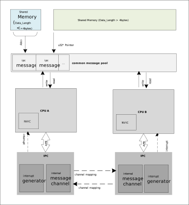
The block diagram of IPC is illustrated in the following figure:
Symmetric Structure
Each CPU is equipped with an identical IPC module.
Full-Duplex Communication Model
Supports bidirectional, full-duplex communication.
Channel Isolation
Channels are designed with hardware-level resource isolation, ensuring data transmission on any channel does not block others.
Supports parallel multi-channel operations (e.g., CPUA can simultaneously transmit sensor data via Channel n and log information via Channel m).
Message Pool
A pre-allocated memory block where each IPC channel sends/receives messages through predefined fixed addresses in the pool.
Shared Memory
For messages larger than 4 bytes: The sender dynamically allocates a shared memory block, writes the memory address into the message pool, and the receiver copies the data locally before the sender releases the shared memory.
For messages ≤4 bytes: Directly write the message into the message pool.
NVIC Interrupt Generator
After data is ready in an IPC channel, writing to specific registers in the IPC block triggers a receive interrupt on the receiving end. Similarly, completing reception can trigger a transmission completion interrupt on the sender side.
Data Flow Model
Sender Process: [Shared Information] → Select available channel → Write to shared memory → Update channel register → Trigger remote interrupt → Remote core reads memory.
Receiver Process: Interrupt notification → Read channel register → Locate shared memory → Copy data locally → Process data → Clear interrupt flag.
IPC Definition
Channel
Concept: An IPC channel is a bidirectional, independent communication path between two IPC entities. Each direction contains multiple channels.
Purpose: Used to transmit send/receive events between two CPUs to achieve inter-core communication.
Component
IPC Configuration Table (IPC_INIT_TABLE)
Purpose: Defines all information for the entire transmission link, including data type, receive/transmit callback functions, interrupt handler parameters, transmission direction, and IPC channel number.
Usage: Users must place an instance of this structure in the IPC_TABLE_DATA_SECTION. The SDK will enable Tx/Rx interrupts for the corresponding channel and register interrupt handlers based on the structure’s members.
Structure Definition:
IPC_TABLE_DATA_SECTION
typedef struct _IPC_INIT_TABLE_ {
   u32 USER_MSG_TYPE;  /* Data type: IPC_USER_DATA (data less than 32 bits) or IPC_USER_POINT (address of data larger than 32 bits) */
   void (*Rxfunc)(void *Data, u32 IrqStatus, u32 ChanNum); /* Receive interrupt callback function */
   void *RxIrqData;    /* Parameter for receive callback function */
   void (*Txfunc)(void *Data, u32 IrqStatus, u32 ChanNum); /* Transmit completion interrupt callback function */
   void *TxIrqData;    /* Parameter for transmit callback function */
   u32 IPC_Direction;  /* Transmission direction */
   u32 IPC_Channel;    /* IPC channel number */
} IPC_INIT_TABLE, *PIPC_INIT_TABLE;
IPC Data Structure (IPC_MSG_STRUCT)
Purpose: In the message pool, each IPC channel has a fixed location to store the
IPC_MSG_STRUCTstructure, which is used to store and transmit data.Structure Definition:
typedef struct ipc_msg_struct {
u32 msg_type;   /* Data type, same as USER_MSG_TYPE */
u32 msg;       /* 32-bit data to transmit or data address (for data larger than 32 bits) */
u32 msg_len;    /* Data length */
u32 rsvd;      /* Reserved field */
} IPC_MSG_STRUCT, *PIPC_MSG_STRUCT, ipc_msg_struct_t;
IPC Standard Usage
Communication Protocol Stack Registration
1.1 Channel Selection
File Path: ameba_ipccfg.h
Select and Define Channels:
Choose and customize channels by uncommenting and modifying their definitions. Example:
1/* Uncomment Channel n and add a functional description */
2#define IPC_N2A_Channeln  n  /*!< User-defined channel: Sensor data transfer from KM0 to KM4 */
3...
4//#define IPC_A2N_Channeln  n  /*!< User-defined channel: Sensor data transfer from KM4 to KM0 */
Confirm Transmission Direction:
1IPC_KM0_TO_KM4 = 0,  // KM0 as sender, KM4 as receiver
2IPC_KM4_TO_KM0 = 1,  // Reverse direction
Guidelines:
Each direction supports 16 physical channels; channel numbers must be within 0–15.
Avoid using system-reserved channels (e.g., those used by Wi-Fi/BT system components).
1.2 Define Receiver Callback Function
The receiver callback function reads messages from the message pool. For pointer-type messages, use
_memcpy()to copy shared data to local memory. The SDK automatically clears interrupt flags after the handler exits.1uint32_t local_buffer[32] = {0}; 2 3/* Receive handler (interrupt context) */ 4void Rx_Channeln_Handler(*Data, u32 IrqStatus, u32 ChanNum) { 5 PIPC_MSG_STRUCT msg = ipc_get_message(IPC_KM0_TO_KM4, IPC_N2A_Channeln); /* Retrieve message metadata */ 6 uint32_t *sensor_data = (uint32_t*)msg->msg; /* Extract data pointer */ 7 _memcpy(local_buffer, (void*)sensor_data, data_size); /* Copy data to local (data length pre-agreed) */ 8 rtos_sema_give(ipc_sema); /* Trigger task-level processing */ 9}
1.3 Register IPC Configuration Table
Register an IPC configuration table for each channel on the receiver side. The SDK automatically enables receive interrupts.
 1 /* Channel configuration table */
 2IPC_TABLE_DATA_SECTION
 3const IPC_INIT_TABLE ipc_chn_config = {
 4    .USER_MSG_TYPE = IPC_USER_POINT,     // Message type: pointer (data > 32 bits)
 5    .Rxfunc        = Rx_Channeln_Handler,
 6    .RxIrqData     = NULL,               // No additional parameters
 7    .Txfunc        = NULL,               // Unidirectional transfer (no TX callback)
 8    .TxIrqData     = NULL,
 9    .IPC_Direction = IPC_KM0_TO_KM4,       // Direction identifier
10    .IPC_Channel   = IPC_N2A_Channeln   // Channel macro
11};
Data Transmission and Reception
2.1. Sender Implementation
Call
ipc_send_message()with direction, channel number, and message.Example: IPC sends a request from KM0 to KM4 via Channel n.
 1 void send_sensor_data(void) {
 2   IPC_MSG_STRUCT ipc_msg_temp;
 3   sensor_buffer = read_sensor();  // Update shared memory
 4
 5   ipc_msg_temp.msg_type = IPC_USER_POINT; // Pointer-based transfer
 6   ipc_msg_temp.msg = (u32)&sensor_buffer;
 7   ipc_msg_temp.msg_len = 1;              // Data length (bytes)
 8   ipc_msg_temp.rsvd = 0;
 9
10   /* Send shared data (SDK API) with timeout handling */
11   ipc_send_message(IPC_KM0_TO_KM4, IPC_N2A_Channeln, &ipc_msg_temp);
12 }
2.2. Receiver Handling
The receiver thread monitors
ipc_sema, processes data upon arrival, and proceeds to next steps.1 /* Interrupt context: Fast data capture */ 2void Rx_Channeln_Handler(*Data, u32 IrqStatus, u32 ChanNum){ 3} 4 5/* Task context: Data processing */ 6void ipc_task(void *param) { 7 while (1) { 8 /* Wait for data arrival */ 9 rtos_sema_take(ipc_sema, RTOS_WAIT_FOREVER); 10 /* Process data (already copied to local_buffer via _memcpy) */ 11 data_pipeline_process(local_buffer); 12 } 13}
Communication Protocol Stack Registration
1.1 Channel Selection
File Path: ameba_ipc.h
Select and Define Channels:
Choose and customize channels by uncommenting and modifying their definitions. Example:
1/* Uncomment Channel n and add a functional description */
2#define IPC_R2M_Channeln  n  /*!< User-defined channel: Sensor data transfer from KR4 to KM4 */
3...
4//#define IPC_M2R_Channeln  n  /*!< User-defined channel: Sensor data transfer from KM4 to KR4 */
Confirm Transmission Direction:
1IPC_KR4_TO_KM4 = 0x00,  // KR4 as sender, KM4 as receiver
2IPC_KR4_TO_DSP = 0x01,  // Reverse direction
Guidelines:
Each direction supports 8 physical channels; channel numbers must be within 0–7.
Avoid using system-reserved channels (e.g., those used by Wi-Fi/BT system components).
1.2 Define Receiver Callback Function
The receiver callback function reads messages from the message pool. For pointer-type messages, use
_memcpy()to copy shared data to local memory. The SDK automatically clears interrupt flags after the handler exits.1uint32_t local_buffer[32] = {0}; 2 3/* Receive handler (interrupt context) */ 4void Rx_Channeln_Handler(*Data, u32 IrqStatus, u32 ChanNum) { 5 PIPC_MSG_STRUCT msg = ipc_get_message(IPC_KR4_TO_KM4, IPC_R2M_Channeln); /* Retrieve message metadata */ 6 uint32_t *sensor_data = (uint32_t*)msg->msg; /* Extract data pointer */ 7 _memcpy(local_buffer, (void*)sensor_data, data_size); /* Copy data to local (data length pre-agreed) */ 8 rtos_sema_give(ipc_sema); /* Trigger task-level processing */ 9}
1.3 Register IPC Configuration Table
Register an IPC configuration table for each channel on the receiver side. The SDK automatically enables receive interrupts.
 1   /* Channel configuration table */
 2IPC_TABLE_DATA_SECTION
 3const IPC_INIT_TABLE ipc_chn_config = {
 4   .USER_MSG_TYPE = IPC_USER_POINT,     // Message type: pointer (data > 32 bits)
 5   .Rxfunc        = Rx_Channeln_Handler,
 6   .RxIrqData     = NULL,               // No additional parameters
 7   .Txfunc        = NULL,               // Unidirectional transfer (no TX callback)
 8   .TxIrqData     = NULL,
 9   .IPC_Direction = IPC_KR4_TO_KM4,     // Direction identifier
10   .IPC_Channel   = IPC_R2M_Channeln    // Channel macro
11};
Data Transmission and Reception
2.1. Sender Implementation
Call
ipc_send_message()with direction, channel number, and message.Example: IPC sends a request from KR4 to KM4 via Channel n.
 1   void send_sensor_data(void) {
 2   IPC_MSG_STRUCT ipc_msg_temp;
 3   sensor_buffer = read_sensor();  // Update shared memory
 4
 5   ipc_msg_temp.msg_type = IPC_USER_POINT; // Pointer-based transfer
 6   ipc_msg_temp.msg = (u32)&sensor_buffer;
 7   ipc_msg_temp.msg_len = 1;              // Data length (bytes)
 8   ipc_msg_temp.rsvd = 0;
 9
10   /* Send shared data (SDK API) with timeout handling */
11   ipc_send_message(IPC_KR4_TO_KM4, IPC_R2M_Channeln, &ipc_msg_temp);
12   }
2.2. Receiver Handling
The receiver thread monitors
ipc_sema, processes data upon arrival, and proceeds to next steps.1 /* Interrupt context: Fast data capture */ 2void Rx_Channeln_Handler(*Data, u32 IrqStatus, u32 ChanNum){ 3} 4 5/* Task context: Data processing */ 6void ipc_task(void *param) { 7 while (1) { 8 /* Wait for data arrival */ 9 rtos_sema_take(ipc_sema, RTOS_WAIT_FOREVER); 10 /* Process data (already copied to local_buffer via _memcpy) */ 11 data_pipeline_process(local_buffer); 12 } 13}
Communication Protocol Stack Registration
1.1 Channel Selection
File Path: ameba_ipc.h
Select and Define Channels:
Choose and customize channels by uncommenting and modifying their definitions. Example:
1/* Uncomment Channel n and add a functional description */
2#define IPC_R2M_Channeln  n  /*!< User-defined channel: Sensor data transfer from KR4 to KM4 */
3...
4//#define IPC_M2R_Channeln  n  /*!< User-defined channel: Sensor data transfer from KM4 to KR4 */
Confirm Transmission Direction:
1IPC_KR4_TO_KM4 = 0x00,  // KR4 as sender, KM4 as receiver
2IPC_KR4_TO_DSP = 0x01,  // Reverse direction
Guidelines:
Each direction supports 8 physical channels; channel numbers must be within 0–7.
Avoid using system-reserved channels (e.g., those used by Wi-Fi/BT system components).
1.2 Define Receiver Callback Function
The receiver callback function reads messages from the message pool. For pointer-type messages, use
_memcpy()to copy shared data to local memory. The SDK automatically clears interrupt flags after the handler exits.1uint32_t local_buffer[32] = {0}; 2 3/* Receive handler (interrupt context) */ 4void Rx_Channeln_Handler(*Data, u32 IrqStatus, u32 ChanNum) { 5 PIPC_MSG_STRUCT msg = ipc_get_message(IPC_KR4_TO_KM4, IPC_R2M_Channeln); /* Retrieve message metadata */ 6 uint32_t *sensor_data = (uint32_t*)msg->msg; /* Extract data pointer */ 7 _memcpy(local_buffer, (void*)sensor_data, data_size); /* Copy data to local (data length pre-agreed) */ 8 rtos_sema_give(ipc_sema); /* Trigger task-level processing */ 9}
1.3 Register IPC Configuration Table
Register an IPC configuration table for each channel on the receiver side. The SDK automatically enables receive interrupts.
 1   /* Channel configuration table */
 2IPC_TABLE_DATA_SECTION
 3const IPC_INIT_TABLE ipc_chn_config = {
 4   .USER_MSG_TYPE = IPC_USER_POINT,     // Message type: pointer (data > 32 bits)
 5   .Rxfunc        = Rx_Channeln_Handler,
 6   .RxIrqData     = NULL,               // No additional parameters
 7   .Txfunc        = NULL,               // Unidirectional transfer (no TX callback)
 8   .TxIrqData     = NULL,
 9   .IPC_Direction = IPC_KR4_TO_KM4,     // Direction identifier
10   .IPC_Channel   = IPC_R2M_Channeln    // Channel macro
11};
Data Transmission and Reception
2.1. Sender Implementation
Call
ipc_send_message()with direction, channel number, and message.Example: IPC sends a request from KR4 to KM4 via Channel n.
 1   void send_sensor_data(void) {
 2   IPC_MSG_STRUCT ipc_msg_temp;
 3   sensor_buffer = read_sensor();  // Update shared memory
 4
 5   ipc_msg_temp.msg_type = IPC_USER_POINT; // Pointer-based transfer
 6   ipc_msg_temp.msg = (u32)&sensor_buffer;
 7   ipc_msg_temp.msg_len = 1;              // Data length (bytes)
 8   ipc_msg_temp.rsvd = 0;
 9
10   /* Send shared data (SDK API) with timeout handling */
11   ipc_send_message(IPC_KR4_TO_KM4, IPC_R2M_Channeln, &ipc_msg_temp);
12   }
2.2. Receiver Handling
The receiver thread monitors
ipc_sema, processes data upon arrival, and proceeds to next steps.1 /* Interrupt context: Fast data capture */ 2void Rx_Channeln_Handler(*Data, u32 IrqStatus, u32 ChanNum){ 3} 4 5/* Task context: Data processing */ 6void ipc_task(void *param) { 7 while (1) { 8 /* Wait for data arrival */ 9 rtos_sema_take(ipc_sema, RTOS_WAIT_FOREVER); 10 /* Process data (already copied to local_buffer via _memcpy) */ 11 data_pipeline_process(local_buffer); 12 } 13}
Communication Protocol Stack Registration
1.1 Channel Selection
File Path: ameba_ipc.h
Select and Define Channels:
Choose and customize channels by uncommenting and modifying their definitions. Example:
1/* Uncomment Channel n and add a functional description */
2#define IPC_R2M_Channeln  n  /*!< User-defined channel: Sensor data transfer from KR4 to KM4 */
3...
4//#define IPC_M2R_Channeln  n  /*!< User-defined channel: Sensor data transfer from KM4 to KR4 */
5//#define IPC_D2R_Channeln  n  /*!< User-defined channel: Sensor data transfer from DSP to KR4 */
6//#define IPC_R2D_Channeln  n  /*!< User-defined channel: Sensor data transfer from KR4 to DSP */
7//#define IPC_D2M_Channeln  n  /*!< User-defined channel: Sensor data transfer from DSP to KM4 */
8//#define IPC_M2D_Channeln  n  /*!< User-defined channel: Sensor data transfer from KM4 to DSP */
Confirm Transmission Direction:
1IPC_KR4_TO_KM4 = 0x00,  // KR4 as sender, KM4 as receiver
2IPC_KR4_TO_DSP = 0x01,  // KR4 as sender, DSP as receiver
3IPC_KM4_TO_KR4 = 0x10,  // KM4 as sender, KR4 as receiver
4IPC_KM4_TO_DSP = 0x11,  // KM4 as sender, DSP as receiver
5IPC_DSP_TO_KR4 = 0x20,  // DSP as sender, KR4 as receiver
6IPC_DSP_TO_KM4 = 0x21,  // DSP as sender, KM4 as receiver
Guidelines:
Each direction supports 8 physical channels; channel numbers must be within 0–7.
Avoid using system-reserved channels (e.g., those used by Wi-Fi/BT system components).
1.2 Define Receiver Callback Function
The receiver callback function reads messages from the message pool. For pointer-type messages, use
_memcpy()to copy shared data to local memory. The SDK automatically clears interrupt flags after the handler exits.1uint32_t local_buffer[32] = {0}; 2 3/* Receive handler (interrupt context) */ 4void Rx_Channeln_Handler(*Data, u32 IrqStatus, u32 ChanNum) { 5 PIPC_MSG_STRUCT msg = ipc_get_message(IPC_KR4_TO_KM4, IPC_R2M_Channeln); /* Retrieve message metadata */ 6 uint32_t *sensor_data = (uint32_t*)msg->msg; /* Extract data pointer */ 7 _memcpy(local_buffer, (void*)sensor_data, data_size); /* Copy data to local (data length pre-agreed) */ 8 rtos_sema_give(ipc_sema); /* Trigger task-level processing */ 9}
1.3 Register IPC Configuration Table
Register an IPC configuration table for each channel on the receiver side. The SDK automatically enables receive interrupts.
 1   /* Channel configuration table */
 2IPC_TABLE_DATA_SECTION
 3const IPC_INIT_TABLE ipc_chn_config = {
 4   .USER_MSG_TYPE = IPC_USER_POINT,     // Message type: pointer (data > 32 bits)
 5   .Rxfunc        = Rx_Channeln_Handler,
 6   .RxIrqData     = NULL,               // No additional parameters
 7   .Txfunc        = NULL,               // Unidirectional transfer (no TX callback)
 8   .TxIrqData     = NULL,
 9   .IPC_Direction = IPC_KR4_TO_KM4,     // Direction identifier
10   .IPC_Channel   = IPC_R2M_Channeln    // Channel macro
11};
Data Transmission and Reception
2.1. Sender Implementation
Call
ipc_send_message()with direction, channel number, and message.Example: IPC sends a request from KR4 to KM4 via Channel n.
 1   void send_sensor_data(void) {
 2   IPC_MSG_STRUCT ipc_msg_temp;
 3   sensor_buffer = read_sensor();  // Update shared memory
 4
 5   ipc_msg_temp.msg_type = IPC_USER_POINT; // Pointer-based transfer
 6   ipc_msg_temp.msg = (u32)&sensor_buffer;
 7   ipc_msg_temp.msg_len = 1;              // Data length (bytes)
 8   ipc_msg_temp.rsvd = 0;
 9
10   /* Send shared data (SDK API) with timeout handling */
11   ipc_send_message(IPC_KR4_TO_KM4, IPC_R2M_Channeln, &ipc_msg_temp);
12}
2.2. Receiver Handling
The receiver thread monitors
ipc_sema, processes data upon arrival, and proceeds to next steps.1 /* Interrupt context: Fast data capture */ 2void Rx_Channeln_Handler(*Data, u32 IrqStatus, u32 ChanNum){ 3} 4 5/* Task context: Data processing */ 6void ipc_task(void *param) { 7 while (1) { 8 /* Wait for data arrival */ 9 rtos_sema_take(ipc_sema, RTOS_WAIT_FOREVER); 10 /* Process data (already copied to local_buffer via _memcpy) */ 11 data_pipeline_process(local_buffer); 12 } 13}
Communication Protocol Stack Registration
1.1 Channel Selection
File Path: ameba_ipc.h
Select and Define Channels:
Choose and customize channels by uncommenting and modifying their definitions. Example:
1/* Uncomment Channel n and add a functional description */
2#define IPC_R2M_Channeln  n  /*!< User-defined channel: Sensor data transfer from KR4 to KM4 */
3...
4//#define IPC_M2R_Channeln  n  /*!< User-defined channel: Sensor data transfer from KM4 to KR4 */
5//#define IPC_D2R_Channeln  n  /*!< User-defined channel: Sensor data transfer from DSP to KR4 */
6//#define IPC_R2D_Channeln  n  /*!< User-defined channel: Sensor data transfer from KR4 to DSP */
7//#define IPC_D2M_Channeln  n  /*!< User-defined channel: Sensor data transfer from DSP to KM4 */
8//#define IPC_M2D_Channeln  n  /*!< User-defined channel: Sensor data transfer from KM4 to DSP */
Confirm Transmission Direction:
1IPC_KR4_TO_KM4 = 0x00,  // KR4 as sender, KM4 as receiver
2IPC_KR4_TO_DSP = 0x01,  // KR4 as sender, DSP as receiver
3IPC_KM4_TO_KR4 = 0x10,  // KM4 as sender, KR4 as receiver
4IPC_KM4_TO_DSP = 0x11,  // KM4 as sender, DSP as receiver
5IPC_DSP_TO_KR4 = 0x20,  // DSP as sender, KR4 as receiver
6IPC_DSP_TO_KM4 = 0x21,  // DSP as sender, KM4 as receiver
Guidelines:
Each direction supports 8 physical channels; channel numbers must be within 0–7.
Avoid using system-reserved channels (e.g., those used by Wi-Fi/BT system components).
1.2 Define Receiver Callback Function
The receiver callback function reads messages from the message pool. For pointer-type messages, use
_memcpy()to copy shared data to local memory. The SDK automatically clears interrupt flags after the handler exits.1uint32_t local_buffer[32] = {0}; 2 3/* Receive handler (interrupt context) */ 4void Rx_Channeln_Handler(*Data, u32 IrqStatus, u32 ChanNum) { 5 PIPC_MSG_STRUCT msg = ipc_get_message(IPC_KR4_TO_KM4, IPC_R2M_Channeln); /* Retrieve message metadata */ 6 uint32_t *sensor_data = (uint32_t*)msg->msg; /* Extract data pointer */ 7 _memcpy(local_buffer, (void*)sensor_data, data_size); /* Copy data to local (data length pre-agreed) */ 8 rtos_sema_give(ipc_sema); /* Trigger task-level processing */ 9}
1.3 Register IPC Configuration Table
Register an IPC configuration table for each channel on the receiver side. The SDK automatically enables receive interrupts.
 1   /* Channel configuration table */
 2IPC_TABLE_DATA_SECTION
 3const IPC_INIT_TABLE ipc_chn_config = {
 4   .USER_MSG_TYPE = IPC_USER_POINT,     // Message type: pointer (data > 32 bits)
 5   .Rxfunc        = Rx_Channeln_Handler,
 6   .RxIrqData     = NULL,               // No additional parameters
 7   .Txfunc        = NULL,               // Unidirectional transfer (no TX callback)
 8   .TxIrqData     = NULL,
 9   .IPC_Direction = IPC_KR4_TO_KM4,     // Direction identifier
10   .IPC_Channel   = IPC_R2M_Channeln    // Channel macro
11};
Data Transmission and Reception
2.1. Sender Implementation
Call
ipc_send_message()with direction, channel number, and message.Example: IPC sends a request from KR4 to KM4 via Channel n.
 1   void send_sensor_data(void) {
 2   IPC_MSG_STRUCT ipc_msg_temp;
 3   sensor_buffer = read_sensor();  // Update shared memory
 4
 5   ipc_msg_temp.msg_type = IPC_USER_POINT; // Pointer-based transfer
 6   ipc_msg_temp.msg = (u32)&sensor_buffer;
 7   ipc_msg_temp.msg_len = 1;              // Data length (bytes)
 8   ipc_msg_temp.rsvd = 0;
 9
10   /* Send shared data (SDK API) with timeout handling */
11   ipc_send_message(IPC_KR4_TO_KM4, IPC_R2M_Channeln, &ipc_msg_temp);
12}
2.2. Receiver Handling
The receiver thread monitors
ipc_sema, processes data upon arrival, and proceeds to next steps.1 /* Interrupt context: Fast data capture */ 2void Rx_Channeln_Handler(*Data, u32 IrqStatus, u32 ChanNum){ 3} 4 5/* Task context: Data processing */ 6void ipc_task(void *param) { 7 while (1) { 8 /* Wait for data arrival */ 9 rtos_sema_take(ipc_sema, RTOS_WAIT_FOREVER); 10 /* Process data (already copied to local_buffer via _memcpy) */ 11 data_pipeline_process(local_buffer); 12 } 13}
Communication Protocol Stack Registration
1.1 Channel Selection
File Path: ameba_ipc.h
Select and Define Channels:
Choose and customize channels by uncommenting and modifying their definitions. Example:
1/* Uncomment Channel n and add a functional description */
2#define IPC_L2N_Channeln  n  /*!< User-defined channel: Sensor data transfer from LP to NP */
3...
4//#define IPC_N2L_Channeln  n  /*!< User-defined channel: Sensor data transfer from NP to LP */
5//#define IPC_L2A_Channeln  n  /*!< User-defined channel: Sensor data transfer from LP to AP */
6//#define IPC_A2L_Channeln  n  /*!< User-defined channel: Sensor data transfer from AP to LP */
7//#define IPC_N2A_Channeln  n  /*!< User-defined channel: Sensor data transfer from NP to AP */
8//#define IPC_A2N_Channeln  n  /*!< User-defined channel: Sensor data transfer from AP to NP */
Confirm Transmission Direction:
1IPC_LP_TO_NP = 0x00,  // LP as sender, NP as receiver
2IPC_LP_TO_AP = 0x01,  // LP as sender, AP as receiver
3IPC_NP_TO_LP = 0x10,  // NP as sender, LP as receiver
4IPC_NP_TO_AP = 0x11,  // NP as sender, AP as receiver
5IPC_AP_TO_LP = 0x20,  // AP as sender, LP as receiver
6IPC_AP_TO_NP = 0x21,  // AP as sender, NP as receiver
Guidelines:
Each direction supports 8 physical channels; channel numbers must be within 0–7.
Avoid using system-reserved channels (e.g., those used by Wi-Fi/BT system components).
1.2 Define Receiver Callback Function
The receiver callback function reads messages from the message pool. For pointer-type messages, use
_memcpy()to copy shared data to local memory. The SDK automatically clears interrupt flags after the handler exits.1uint32_t local_buffer[32] = {0}; 2 3/* Receive handler (interrupt context) */ 4void Rx_Channeln_Handler(*Data, u32 IrqStatus, u32 ChanNum) { 5 PIPC_MSG_STRUCT msg = ipc_get_message(IPC_LP_TO_NP, IPC_L2N_Channeln); /* Retrieve message metadata */ 6 uint32_t *sensor_data = (uint32_t*)msg->msg; /* Extract data pointer */ 7 _memcpy(local_buffer, (void*)sensor_data, data_size); /* Copy data to local (data length pre-agreed) */ 8 rtos_sema_give(ipc_sema); /* Trigger task-level processing */ 9}
1.3 Register IPC Configuration Table
Register an IPC configuration table for each channel on the receiver side. The SDK automatically enables receive interrupts.
 1 /* Channel configuration table */
 2IPC_TABLE_DATA_SECTION
 3const IPC_INIT_TABLE ipc_chn_config = {
 4   .USER_MSG_TYPE = IPC_USER_POINT,     // Message type: pointer (data > 32 bits)
 5   .Rxfunc        = Rx_Channeln_Handler,
 6   .RxIrqData     = NULL,               // No additional parameters
 7   .Txfunc        = NULL,               // Unidirectional transfer (no TX callback)
 8   .TxIrqData     = NULL,
 9   .IPC_Direction = IPC_LP_TO_NP,     // Direction identifier
10   .IPC_Channel   = IPC_L2N_Channeln    // Channel macro
11};
Data Transmission and Reception
2.1. Sender Implementation
Call
ipc_send_message()with direction, channel number, and message.Example: IPC sends a request from LP to NP via Channel n.
 1 void send_sensor_data(void) {
 2   IPC_MSG_STRUCT ipc_msg_temp;
 3   sensor_buffer = read_sensor();  // Update shared memory
 4
 5   ipc_msg_temp.msg_type = IPC_USER_POINT; // Pointer-based transfer
 6   ipc_msg_temp.msg = (u32)&sensor_buffer;
 7   ipc_msg_temp.msg_len = 1;              // Data length (bytes)
 8   ipc_msg_temp.rsvd = 0;
 9
10   /* Send shared data (SDK API) with timeout handling */
11   ipc_send_message(IPC_LP_TO_NP, IPC_L2N_Channeln, &ipc_msg_temp);
12}
2.2. Receiver Handling
The receiver thread monitors
ipc_sema, processes data upon arrival, and proceeds to next steps.1 /* Interrupt context: Fast data capture */ 2void Rx_Channeln_Handler(*Data, u32 IrqStatus, u32 ChanNum){ 3} 4 5/* Task context: Data processing */ 6void ipc_task(void *param) { 7 while (1) { 8 /* Wait for data arrival */ 9 rtos_sema_take(ipc_sema, RTOS_WAIT_FOREVER); 10 /* Process data (already copied to local_buffer via _memcpy) */ 11 data_pipeline_process(local_buffer); 12 } 13}
Communication Protocol Stack Registration
1.1 Channel Selection
File Path: ameba_ipccfg.h
Select and Define Channels:
Choose and customize channels by uncommenting and modifying their definitions. Example:
1/* Uncomment Channel n and add a functional description */
2#define IPC_N2A_Channeln  n  /*!< User-defined channel: Sensor data transfer from NP to AP */
3...
4//#define IPC_A2N_Channeln  n  /*!< User-defined channel: Sensor data transfer from AP to NP */
Confirm Transmission Direction:
1IPC_NP_TO_AP = 0,  // NP as sender, AP as receiver
2IPC_AP_TO_NP = 1,  // Reverse direction
Guidelines:
Each direction supports 16 physical channels; channel numbers must be within 0–15.
Avoid using system-reserved channels (e.g., those used by Wi-Fi/BT system components).
1.2 Define Receiver Callback Function
The receiver callback function reads messages from the message pool. For pointer-type messages, use
_memcpy()to copy shared data to local memory. The SDK automatically clears interrupt flags after the handler exits.1uint32_t local_buffer[32] = {0}; 2 3/* Receive handler (interrupt context) */ 4void Rx_Channeln_Handler(*Data, u32 IrqStatus, u32 ChanNum) { 5 PIPC_MSG_STRUCT msg = ipc_get_message(IPC_NP_TO_AP, IPC_N2A_Channeln); /* Retrieve message metadata */ 6 uint32_t *sensor_data = (uint32_t*)msg->msg; /* Extract data pointer */ 7 _memcpy(local_buffer, (void*)sensor_data, data_size); /* Copy data to local (data length pre-agreed) */ 8 rtos_sema_give(ipc_sema); /* Trigger task-level processing */ 9}
1.3 Register IPC Configuration Table
Register an IPC configuration table for each channel on the receiver side. The SDK automatically enables receive interrupts.
 1 /* Channel configuration table */
 2IPC_TABLE_DATA_SECTION
 3const IPC_INIT_TABLE ipc_chn_config = {
 4   .USER_MSG_TYPE = IPC_USER_POINT,     // Message type: pointer (data > 32 bits)
 5   .Rxfunc        = Rx_Channeln_Handler,
 6   .RxIrqData     = NULL,               // No additional parameters
 7   .Txfunc        = NULL,               // Unidirectional transfer (no TX callback)
 8   .TxIrqData     = NULL,
 9   .IPC_Direction = IPC_NP_TO_AP,     // Direction identifier
10   .IPC_Channel   = IPC_N2A_Channeln    // Channel macro
11};
Data Transmission and Reception
2.1. Sender Implementation
Call
ipc_send_message()with direction, channel number, and message.Example: IPC sends a request from NP to AP via Channel n.
 1 void send_sensor_data(void) {
 2   IPC_MSG_STRUCT ipc_msg_temp;
 3   sensor_buffer = read_sensor();  // Update shared memory
 4
 5   ipc_msg_temp.msg_type = IPC_USER_POINT; // Pointer-based transfer
 6   ipc_msg_temp.msg = (u32)&sensor_buffer;
 7   ipc_msg_temp.msg_len = 1;              // Data length (bytes)
 8   ipc_msg_temp.rsvd = 0;
 9
10   /* Send shared data (SDK API) with timeout handling */
11   ipc_send_message(IPC_NP_TO_AP, IPC_N2A_Channeln, &ipc_msg_temp);
12 }
2.2. Receiver Handling
The receiver thread monitors
ipc_sema, processes data upon arrival, and proceeds to next steps.1 /* Interrupt context: Fast data capture */ 2void Rx_Channeln_Handler(*Data, u32 IrqStatus, u32 ChanNum){ 3} 4 5/* Task context: Data processing */ 6void ipc_task(void *param) { 7 while (1) { 8 /* Wait for data arrival */ 9 rtos_sema_take(ipc_sema, RTOS_WAIT_FOREVER); 10 /* Process data (already copied to local_buffer via _memcpy) */ 11 data_pipeline_process(local_buffer); 12 } 13}
Communication Protocol Stack Registration
1.1 Channel Selection
File Path: ameba_ipccfg.h
Select and Define Channels:
Choose and customize channels by uncommenting and modifying their definitions. Example:
1/* Uncomment Channel n and add a functional description */
2#define IPC_N2A_Channeln  n  /*!< User-defined channel: Sensor data transfer from NP to AP */
3...
4//#define IPC_A2N_Channeln  n  /*!< User-defined channel: Sensor data transfer from AP to NP */
Confirm Transmission Direction:
1IPC_NP_TO_AP = 0,  // NP as sender, AP as receiver
2IPC_AP_TO_NP = 1,  // Reverse direction
Guidelines:
Each direction supports 16 physical channels; channel numbers must be within 0–15.
Avoid using system-reserved channels (e.g., those used by Wi-Fi/BT system components).
1.2 Define Receiver Callback Function
The receiver callback function reads messages from the message pool. For pointer-type messages, use
_memcpy()to copy shared data to local memory. The SDK automatically clears interrupt flags after the handler exits.1uint32_t local_buffer[32] = {0}; 2 3/* Receive handler (interrupt context) */ 4void Rx_Channeln_Handler(*Data, u32 IrqStatus, u32 ChanNum) { 5 PIPC_MSG_STRUCT msg = ipc_get_message(IPC_NP_TO_AP, IPC_N2A_Channeln); /* Retrieve message metadata */ 6 uint32_t *sensor_data = (uint32_t*)msg->msg; /* Extract data pointer */ 7 _memcpy(local_buffer, (void*)sensor_data, data_size); /* Copy data to local (data length pre-agreed) */ 8 rtos_sema_give(ipc_sema); /* Trigger task-level processing */ 9}
1.3 Register IPC Configuration Table
Register an IPC configuration table for each channel on the receiver side. The SDK automatically enables receive interrupts.
 1 /* Channel configuration table */
 2IPC_TABLE_DATA_SECTION
 3const IPC_INIT_TABLE ipc_chn_config = {
 4   .USER_MSG_TYPE = IPC_USER_POINT,     // Message type: pointer (data > 32 bits)
 5   .Rxfunc        = Rx_Channeln_Handler,
 6   .RxIrqData     = NULL,               // No additional parameters
 7   .Txfunc        = NULL,               // Unidirectional transfer (no TX callback)
 8   .TxIrqData     = NULL,
 9   .IPC_Direction = IPC_NP_TO_AP,     // Direction identifier
10   .IPC_Channel   = IPC_N2A_Channeln    // Channel macro
11};
Data Transmission and Reception
2.1. Sender Implementation
Call
ipc_send_message()with direction, channel number, and message.Example: IPC sends a request from NP to AP via Channel n.
 1 void send_sensor_data(void) {
 2   IPC_MSG_STRUCT ipc_msg_temp;
 3   sensor_buffer = read_sensor();  // Update shared memory
 4
 5   ipc_msg_temp.msg_type = IPC_USER_POINT; // Pointer-based transfer
 6   ipc_msg_temp.msg = (u32)&sensor_buffer;
 7   ipc_msg_temp.msg_len = 1;              // Data length (bytes)
 8   ipc_msg_temp.rsvd = 0;
 9
10   /* Send shared data (SDK API) with timeout handling */
11   ipc_send_message(IPC_NP_TO_AP, IPC_N2A_Channeln, &ipc_msg_temp);
12 }
2.2. Receiver Handling
The receiver thread monitors
ipc_sema, processes data upon arrival, and proceeds to next steps.1 /* Interrupt context: Fast data capture */ 2void Rx_Channeln_Handler(*Data, u32 IrqStatus, u32 ChanNum){ 3} 4 5/* Task context: Data processing */ 6void ipc_task(void *param) { 7 while (1) { 8 /* Wait for data arrival */ 9 rtos_sema_take(ipc_sema, RTOS_WAIT_FOREVER); 10 /* Process data (already copied to local_buffer via _memcpy) */ 11 data_pipeline_process(local_buffer); 12 } 13}
Communication Protocol Stack Registration
1.1 Channel Selection
File Path: ameba_ipccfg.h
Select and Define Channels:
Choose and customize channels by uncommenting and modifying their definitions. Example:
1/* Uncomment Channel n and add a functional description */
2#define IPC_N2A_Channeln  n  /*!< User-defined channel: Data transfer from NP to AP */
3...
4//#define IPC_A2N_Channeln  n  /*!< User-defined channel: Data transfer from AP to NP */
5//#define IPC_N2V_Channeln  n  /*!< User-defined channel: Data transfer from NP to VP */
6//#define IPC_V2N_Channeln  n  /*!< User-defined channel: Data transfer from VP to NP */
7//#define IPC_N2F_Channeln  n  /*!< User-defined channel: Data transfer from NP to FP */
8//#define IPC_F2N_Channeln  n  /*!< User-defined channel: Data transfer from FP to NP */
Confirm Transmission Direction:
 1#define IPC_NP_TO_FP   0   // NP as sender, FP as receiver
 2#define IPC_NP_TO_AP   1   // NP as sender, AP as receiver
 3#define IPC_NP_TO_VP   2   // NP as sender, VP as receiver
 4#define IPC_VP_TO_NP   3   // VP as sender, NP as receiver
 5#define IPC_VP_TO_AP   4   // VP as sender, AP as receiver
 6#define IPC_VP_TO_FP   5   // VP as sender, FP as receiver
 7#define IPC_AP_TO_NP   6   // AP as sender, NP as receiver
 8#define IPC_AP_TO_VP   7   // AP as sender, VP as receiver
 9#define IPC_AP_TO_FP   8   // AP as sender, FP as receiver
10#define IPC_FP_TO_NP   9   // FP as sender, NP as receiver
11#define IPC_FP_TO_VP   10  // FP as sender, VP as receiver
12#define IPC_FP_TO_AP   11  // FP as sender, AP as receiver
Guidelines:
Each direction supports 16 channels; channel numbers must be within 0–15.
Avoid using system-reserved channels (e.g., those used by Wi-Fi/BT system components).
1.2 Define Receiver Callback Function
The receiver callback function reads messages from the message pool. For pointer-type messages, use
_memcpy()to copy shared data to local memory. The SDK automatically clears interrupt flags after the handler exits.1uint32_t local_buffer[32] = {0}; 2 3/* Receive handler (interrupt context) */ 4void Rx_Channeln_Handler(void *Data, u32 IrqStatus, u32 ChanNum) { 5 PIPC_MSG_STRUCT msg = ipc_get_message(IPC_NP_TO_AP, IPC_N2A_Channeln); /* Retrieve message metadata */ 6 uint32_t *sensor_data = (uint32_t*)msg->msg; /* Extract data pointer */ 7 _memcpy(local_buffer, (void*)sensor_data, data_size); /* Copy data to local (data length pre-agreed) */ 8 rtos_sema_give(ipc_sema); /* Trigger task-level processing */ 9}
1.3 Register IPC Configuration Table
Register an IPC configuration table for each channel on the receiver side. The SDK automatically enables receive interrupts.
 1 /* Channel configuration table */
 2IPC_TABLE_DATA_SECTION
 3const IPC_INIT_TABLE ipc_chn_config = {
 4   .USER_MSG_TYPE = IPC_USER_POINT,     // Message type: pointer (data > 32 bits)
 5   .Rxfunc        = Rx_Channeln_Handler,
 6   .RxIrqData     = NULL,               // No additional parameters
 7   .Txfunc        = NULL,               // Unidirectional transfer (no TX callback)
 8   .TxIrqData     = NULL,
 9   .IPC_Direction = IPC_NP_TO_AP,       // Direction identifier
10   .IPC_Channel   = IPC_N2A_Channeln   // Channel macro
11};
Data Transmission and Reception
2.1. Sender Implementation
Call
ipc_send_message()with direction, channel number, and message.Example: IPC sends a request from NP to AP via Channel n.
 1 void send_sensor_data(void) {
 2   IPC_MSG_STRUCT ipc_msg_temp;
 3   sensor_buffer = read_sensor();  // Update shared memory
 4
 5   ipc_msg_temp.msg_type = IPC_USER_POINT; // Pointer-based transfer
 6   ipc_msg_temp.msg = (u32)&sensor_buffer;
 7   ipc_msg_temp.msg_len = 1;              // Data length (bytes)
 8   ipc_msg_temp.rsvd = 0;
 9
10   /* Send shared data (SDK API) with timeout handling */
11   ipc_send_message(IPC_NP_TO_AP, IPC_N2A_Channeln, &ipc_msg_temp);
12 }
2.2. Receiver Handling
The receiver thread monitors
ipc_sema, processes data upon arrival, and proceeds to next steps.1 /* Interrupt context: Fast data capture */ 2void Rx_Channeln_Handler(void *Data, u32 IrqStatus, u32 ChanNum) { 3} 4 5/* Task context: Data processing */ 6void ipc_task(void *param) { 7 while (1) { 8 /* Wait for data arrival */ 9 rtos_sema_take(ipc_sema, RTOS_WAIT_FOREVER); 10 /* Process data (already copied to local_buffer via _memcpy) */ 11 data_pipeline_process(local_buffer); 12 } 13}
IPC Advanced Usage
Application Scenarios
The sender must immediately detect whether the receiver has accepted the transmission. For example:
When a channel is busy, the sending thread should yield CPU scheduling to avoid polling and resource contention, ensuring smooth system operation.
When the channel becomes idle, the receiver should promptly detect the status change and handle it accordingly.
Transmission Acknowledgment Configuration
Define Transmitter Callback Function
If the
IPC_INIT_TABLEinitializes a transmitter callback function, the SDK will automatically:Enable the transmission completion interrupt for channel n.
Initialize the transmission semaphore (
ipc_Semaphore) when the channel is busy and wait for its release to yield scheduling, preventing prolonged CPU occupation.
Recommended Practice: Register this handler as
IPC_TXHandler()from ameba_ipc_api.c. This function releases the semaphore for channel n (ipc_Semaphore).Workflow:
The sender thread calls
ipc_send_message().If the channel is busy, the thread attempts to acquire
ipc_Semaphore.While waiting, the thread yields CPU scheduling, minimizing resource usage.
The SDK automatically clears interrupt flags after IRQ exits.
void IPC_TXHandler(void *Data, u32 IrqStatus, u32 ChanNum)
{
   UNUSED(Data);
   UNUSED(IrqStatus);

   u32 CPUID = SYS_CPUID();
   IPC_TypeDef *IPCx = IPC_GetDevById(CPUID);
   /* Disable tx channeln interrupt */
   IPC_INTConfig(IPCx, ChanNum, DISABLE);

   if (ipc_Semaphore[ChanNum - IPC_TX_CHANNEL_SHIFT] != NULL) {
      /* Release semaphore */
      rtos_sema_give(ipc_Semaphore[ChanNum - IPC_TX_CHANNEL_SHIFT]);
   }
}
Register IPC Configuration Table
Extend the existing IPC Standard Usage configuration by adding tx_func and tx_irq_data.
Both cores must compile this table to enable bidirectional communication.
/* Channel configuration table */
IPC_TABLE_DATA_SECTION
const IPC_INIT_TABLE ipc_chn_config = {
   .msg_type    = IPC_USER_POINT,     // Transfer mode: pointer (data >32 bits)
   .rx_func     = rx_func,
   .rx_irq_data = rx_irq_data,
   .tx_func     = IPC_TXHandler,     // Transmit completion callback
   .tx_irq_data = NULL,
   .direction   = IPC_Direction,      // Direction identifier
   .channel_num = IPC_Channel         // Channel macro
};
Troubleshooting
Channel Conflict
Phenomenon |
Error log printed: Channel Conflict for CPU A Channel n ! Ignore If CPU Has Reset |
Cause |
Two interrupt callback functions are registered for the same channel |
Solution |
Check the IPC configuration table ( |
Send Timeout
Phenomenon |
Error log printed: IPC Request Timeout |
Cause |
The sender attempts to send data through the same channel again before the previous data has been received |
Solution |
|
Semaphore Acquisition Timeout
Phenomenon |
Error log printed: IPC Get Semaphore Timeout |
Cause |
The sender has registered a send completion callback function. The sender attempts to send data through the same channel again before the previous data has been received, resulting in a timeout while waiting for a semaphore |
Solution |
|
No Response from Receiver
Phenomenon 1 |
A specific IPC channel on the receiver is not responding |
Cause |
The interrupt for that channel on the receiver has been mistakenly disabled |
Solution |
Check if the interrupt for the channel has been mistakenly disabled on the receiver and enable it by calling |
Phenomenon 2 |
All IPC channels on the receiver are not responding |
Cause |
|
Solution |
|
IPC Application
TBD
Raw API
IPC Exported Types
-
typedef struct _IPC_INIT_TABLE_ IPC_INIT_TABLE
IPC Init Table Definition.
-
typedef void (*IPC_IRQ_FUN)(void *Data, u32 IrqStatus, u32 ChanNum)
IPC IRQ Function Definition.
-
typedef struct ipc_msg_struct IPC_MSG_STRUCT
IPC Message Definition.
-
typedef struct _IPC_INIT_TABLE_ *PIPC_INIT_TABLE
-
typedef struct ipc_msg_struct *PIPC_MSG_STRUCT
-
enum USER_MSG_TYP_DEF
IPC User Message Type Definition.
Values:
/* Message payload is a pointer. */
IPC_USER_POINT = 0

/* Message payload is inline data. */
IPC_USER_DATA = 1
-
struct _IPC_INIT_TABLE_
IPC Init Table Definition.
Public Members
-
u32 USER_MSG_TYPE
User-defined message type.
-
void (*Rxfunc)(void *Data, u32 IrqStatus, u32 ChanNum)
Pointer to the RX interrupt callback function.
-
void *RxIrqData
Data passed to the RX callback.
-
void (*Txfunc)(void *Data, u32 IrqStatus, u32 ChanNum)
Pointer to the TX interrupt callback function.
-
void *TxIrqData
Data passed to the TX callback.
-
IPC_Direction_Mode IPC_Direction
IPC transfer direction, this parameter can be a value of IPC_Direction_Mode.
-
u32 IPC_Channel
IPC TX channel, this parameter can be a value of IPC TX Channel.
-
u32 USER_MSG_TYPE
-
struct ipc_msg_struct
IPC Message Definition.
Public Members
-
u32 msg_type
Message type identifier.
-
u32 msg
Message payload or address.
-
u32 msg_len
Length of the message payload.
-
u32 rsvd
Reserved.
-
u32 msg_type
-
typedef struct ipc_msg_struct ipc_msg_struct_t
-
enum IPC_Direction_Mode
IPC direction mode definition.
Values:
/* KM0 send request to KM4 */
IPC_KM0_TO_KM4 = 0

/* KM4 send request to KM0 */
IPC_KM4_TO_KM0 = 1

/* Maximum sentinel value for direction mode. */
IPC_DIR_MODE_MAX = 0xFFFFFFFF
-
enum IPC_Direction_Mode
IPC direction mode definition.
Values:
/* KR4 send request to KM4 */
IPC_KR4_TO_KM4 = 0x00

/* KR4 send request to DSP */
IPC_KR4_TO_DSP = 0x01

/* KM4 send request to KR4 */
IPC_KM4_TO_KR4 = 0x10

/* KM4 send request to DSP */
IPC_KM4_TO_DSP = 0x11

/* DSP send request to KR4 */
IPC_DSP_TO_KR4 = 0x20

/* DSP send request to KM4 */
IPC_DSP_TO_KM4 = 0x21

/* Maximum sentinel value for direction mode. */
IPC_DIR_MODE_MAX = 0xFFFFFFFF
STRUCTURE_REF=IPC_Direction_Mode_RTL8720E
STRUCTURE_REF=IPC_Direction_Mode_RTL8720E
STRUCTURE_REF=IPC_Direction_Mode_RTL8720E
-
enum IPC_Direction_Mode
IPC direction mode definition.
Values:
/* LP send request to NP */
IPC_LP_TO_NP = 0x00

/* LP send request to AP */
IPC_LP_TO_AP = 0x01

/* NP send request to LP */
IPC_NP_TO_LP = 0x10

/* NP send request to AP */
IPC_NP_TO_AP = 0x11

/* AP send request to LP */
IPC_AP_TO_LP = 0x20

/* AP send request to NP */
IPC_AP_TO_NP = 0x21

/* Maximum sentinel value for direction mode. */
IPC_DIR_MODE_MAX = 0xFFFFFFFF
-
enum IPC_Direction_Mode
IPC direction mode definition.
Values:
/* NP send request to AP */
IPC_NP_TO_AP = 0

/* AP send request to NP */
IPC_AP_TO_NP = 1

/* Maximum sentinel value for direction mode. */
IPC_DIR_MODE_MAX = 0xFFFFFFFF
STRUCTURE_REF=IPC_Direction_Mode_RTL8721F
-
typedef struct ipc_data_struct IPC_DATA_STRUCT
IPC Data Structure Definition.
-
typedef struct ipc_data_struct *PIPC_DATA_STRUCT
-
struct ipc_data_struct
IPC Data Structure Definition.
Public Members
-
u32 *data
Pointer to the data buffer.
-
u32 data_len
Length of the data buffer in bytes.
-
u32 rsvd[2]
Reserved.
-
u32 *data
-
typedef struct ipc_data_struct ipc_data_struct_t
IPC Exported Constants
Not supported.
Not supported.
Not supported.
Not supported.
Not supported.
Not supported.
Not supported.
/* Maximum RX data length in bytes. */
#define IPC_RX_DATA_LEN_MAX 16

/* IPC TX FIFO level threshold. */
#define IPC_TX_LEVEVL 15

/* IPC TX operation timeout value. */
#define IPC_TX_TIMEOUT 0x9c40
IPC Interrupt Mode
/* IPC TX channel empty interrupt mode. */
#define IPC_TX_EMPTY ((u32)0x00000001)

/* IPC RX channel full interrupt mode. */
#define IPC_RX_FULL ((u32)0x00000002)

/* Check if IPC interrupt mode value is valid. */
#define IS_IPC_INTR_MODE (((MODE) == IPC_TX_EMPTY) || \
    ((MODE) == IPC_RX_FULL))
IPC Return Value
/* IPC semaphore timeout error code. */
#define IPC_SEMA_TIMEOUT 3

/* IPC request timeout error code. */
#define IPC_REQ_TIMEOUT 2

/* IPC message sent successfully. */
#define IPC_SEND_SUCCESS 0

/* IPC send timeout error code. */
#define IPC_SEND_TIMEOUT 1

/* IPC semaphore maximum delay in ms (65536ms). */
#define IPC_SEMA_MAX_DELAY 0x10000
Not supported.
Not supported.
Not supported.
Not supported.
Not supported.
Not supported.
Not supported.
/* RX memory allocation failure. */
#define IPC_RX_MALLOC_FAIL 6

/* RX channel error. */
#define IPC_RX_CH_ERROE 5

/* RX FIFO is empty. */
#define IPC_RX_FIFO_EMPTY 4

/* Message received successfully. */
#define IPC_RECEIVE_SUCCESS 0
IPC TX Channel Number
/* Total number of IPC TX channels. */
#define IPC_TX_CHANNEL_NUM 16
IPC TX Channel Switch
/* Total number of IPC channels (TX + RX). */
#define IPC_CHANNEL_NUM 32
/* Extract TX channel index from channel value. */
#define IPC_TX_CHANNEL_SWITCH ((u32)((x) & 0x0000000F))
Not supported.
Not supported.
Not supported.
Not supported.
Not supported.
/* Extract TX channel index from channel value. */
#define IPC_TX_CHANNEL_SWITCH ((u32)((x) & 0x0000000F))
/* Extract TX channel index from channel value. */
#define IPC_TX_CHANNEL_SWITCH ((u32)((x) & 0x0000000F))
IPC Peripheral Definition
/* Check if IPC peripheral pointer is valid. */
#define IS_IPC_ALL_PERIPH (((PERIPH) == IPCKM0_DEV) || \
    ((PERIPH) == IPCKM4_DEV))
/* Check if IPC peripheral pointer is valid. */
#define IS_IPC_ALL_PERIPH (((PERIPH) == IPCKR4_DEV) || \
    ((PERIPH) == IPCKM4_DEV)) || \
    ((PERIPH) == IPCDSP_DEV))
/* Check if IPC peripheral pointer is valid. */
#define IS_IPC_ALL_PERIPH (((PERIPH) == IPCKR4_DEV) || \
    ((PERIPH) == IPCKM4_DEV)) || \
    ((PERIPH) == IPCDSP_DEV))
/* Check if IPC peripheral pointer is valid. */
#define IS_IPC_ALL_PERIPH (((PERIPH) == IPCKR4_DEV) || \
    ((PERIPH) == IPCKM4_DEV)) || \
    ((PERIPH) == IPCDSP_DEV))
/* Check if IPC peripheral pointer is valid. */
#define IS_IPC_ALL_PERIPH (((PERIPH) == IPCKR4_DEV) || \
    ((PERIPH) == IPCKM4_DEV)) || \
    ((PERIPH) == IPCDSP_DEV))
/* Check if IPC peripheral pointer is valid. */
#define IS_IPC_ALL_PERIPH (((PERIPH) == IPCLP_DEV) || \
    ((PERIPH) == IPCNP_DEV)) || \
    ((PERIPH) == IPCAP_DEV))
/* Check if IPC peripheral pointer is valid. */
#define IS_IPC_ALL_PERIPH (((PERIPH) == IPCNP_DEV) || \
    ((PERIPH) == IPCAP_DEV))
/* Check if IPC peripheral pointer is valid. */
#define IS_IPC_ALL_PERIPH (((PERIPH) == IPCNP_DEV) || \
    ((PERIPH) == IPCAP_DEV))
IPC Valid Channel Number
/* Check if IPC channel number is valid. */
#define IS_IPC_VALID_CHNUM ((NUM) < 16)
/* Check if IPC channel number is valid. */
#define IS_IPC_VALID_CHNUM ((NUM) < 8)
/* Check if IPC channel number is valid. */
#define IS_IPC_VALID_CHNUM ((NUM) < 8)
/* Check if IPC channel number is valid. */
#define IS_IPC_VALID_CHNUM ((NUM) < 8)
/* Check if IPC channel number is valid. */
#define IS_IPC_VALID_CHNUM ((NUM) < 8)
/* Check if IPC channel number is valid. */
#define IS_IPC_VALID_CHNUM ((NUM) < 8)
/* Check if IPC channel number is valid. */
#define IS_IPC_VALID_CHNUM ((NUM) < 16)
/* Check if IPC channel number is valid. */
#define IS_IPC_VALID_CHNUM ((NUM) < 16)
IPC Valid RX Channel
/* Check if IPC RX channel number is valid. */
#define IS_IPC_RX_CHNUM ((NUM) < 16)
Not supported.
Not supported.
Not supported.
Not supported.
Not supported.
/* Check if IPC RX channel number is valid. */
#define IS_IPC_RX_CHNUM ((NUM) < 16)
/* Check if IPC RX channel number is valid. */
#define IS_IPC_RX_CHNUM ((NUM) < 16)
IPC Channel
Not supported.
/* Extract TX channel index from channel value. */
#define IPC_TX_CHANNEL_SWITCH ((u32)(((x >> 4) & 0x0000000F)))

/* Total number of IPC TX0 channels. */
#define IPC_TX0_CHANNEL_NUM 8

/* Extract TX0 channel index from channel value. */
#define IPC_TX0_CHANNEL_SWITCH ((u32)((x) & 0x0000000F))

/* Check if IPC RX channel number is valid. */
#define IS_IPC_RX_CHNUM ((NUM) >= 16)
/* Extract TX channel index from channel value. */
#define IPC_TX_CHANNEL_SWITCH ((u32)(((x >> 4) & 0x0000000F)))

/* Total number of IPC TX0 channels. */
#define IPC_TX0_CHANNEL_NUM 8

/* Extract TX0 channel index from channel value. */
#define IPC_TX0_CHANNEL_SWITCH ((u32)((x) & 0x0000000F))

/* Check if IPC RX channel number is valid. */
#define IS_IPC_RX_CHNUM ((NUM) >= 16)
/* Extract TX channel index from channel value. */
#define IPC_TX_CHANNEL_SWITCH ((u32)(((x >> 4) & 0x0000000F)))

/* Total number of IPC TX0 channels. */
#define IPC_TX0_CHANNEL_NUM 8

/* Extract TX0 channel index from channel value. */
#define IPC_TX0_CHANNEL_SWITCH ((u32)((x) & 0x0000000F))

/* Check if IPC RX channel number is valid. */
#define IS_IPC_RX_CHNUM ((NUM) >= 16)
/* Extract TX channel index from channel value. */
#define IPC_TX_CHANNEL_SWITCH ((u32)(((x >> 4) & 0x0000000F)))

/* Total number of IPC TX0 channels. */
#define IPC_TX0_CHANNEL_NUM 8

/* Extract TX0 channel index from channel value. */
#define IPC_TX0_CHANNEL_SWITCH ((u32)((x) & 0x0000000F))

/* Check if IPC RX channel number is valid. */
#define IS_IPC_RX_CHNUM ((NUM) >= 16)
/* Extract TX channel index from channel value. */
#define IPC_TX_CHANNEL_SWITCH ((u32)(((x >> 4) & 0x0000000F)))

/* Total number of IPC TX0 channels. */
#define IPC_TX0_CHANNEL_NUM 8

/* Extract TX0 channel index from channel value. */
#define IPC_TX0_CHANNEL_SWITCH ((u32)((x) & 0x0000000F))

/* Check if IPC RX channel number is valid. */
#define IS_IPC_RX_CHNUM ((NUM) >= 16)
Not supported.
Not supported.
IPC Valid Semaphore ID
/* Check if IPC semaphore ID is valid. */
#define IS_IPC_VALID_SEMID ((SEM_ID) < 64)
/* Check if IPC semaphore ID is valid. */
#define IS_IPC_VALID_SEMID ((SEM_ID) < IPC_SEM_MAX)
/* Check if IPC semaphore ID is valid. */
#define IS_IPC_VALID_SEMID ((SEM_ID) < IPC_SEM_MAX)
/* Check if IPC semaphore ID is valid. */
#define IS_IPC_VALID_SEMID ((SEM_ID) < IPC_SEM_MAX)
/* Check if IPC semaphore ID is valid. */
#define IS_IPC_VALID_SEMID ((SEM_ID) < IPC_SEM_MAX)
/* Check if IPC semaphore ID is valid. */
#define IS_IPC_VALID_SEMID ((SEM_ID) < 16)
/* Check if IPC semaphore ID is valid. */
#define IS_IPC_VALID_SEMID ((SEM_ID) < 64)
/* Total number of IPC semaphores. */
#define IPC_SEMA_NUM (64)

/* Check if IPC semaphore ID is valid. */
#define IS_IPC_VALID_SEMID ((SEM_ID) < IPC_SEMA_NUM)
IPC TX Channel Shift
/* Bit shift for IPC TX channel index. */
#define IPC_TX_CHANNEL_SHIFT 16
Not supported.
Not supported.
Not supported.
Not supported.
Not supported.
/* Bit shift for IPC TX channel index. */
#define IPC_TX_CHANNEL_SHIFT 16
/* Bit shift for IPC TX channel index. */
#define IPC_TX_CHANNEL_SHIFT 16
IPC TX Channel
/* NP --> AP Tickless indicate */
#define IPC_N2A_TICKLESS_INDICATION 0

/* NP --> AP Wakeup */
#define IPC_N2A_WAKE_AP 1

/* NP --> AP FW Info */
#define IPC_N2A_WIFI_FW_INFO 2

/* NP --> AP Flash Program REQUEST */
#define IPC_N2A_FLASHPG_REQ 3

/* NP --> AP Loguart Rx Switch */
#define IPC_N2A_LOGUART_RX_SWITCH 4

/* NP --> AP COEX API Exchange */
#define IPC_N2A_COEX_API_TRAN 5

/* NP --> AP WIFI Message Exchange */
#define IPC_N2A_WIFI_TRX_TRAN 6

/* NP --> AP API WIFI Message Exchange */
#define IPC_N2A_WIFI_API_TRAN 7

/* AP --> NP Tickless indicate */
#define IPC_A2N_TICKLESS_INDICATION 0

/* AP --> NP FW Info */
#define IPC_A2N_WIFI_FW_INFO 1

/* AP --> NP Wakeup */
#define IPC_A2N_WAKE_AP 2

/* AP --> NP Flash Program Request */
#define IPC_A2N_FLASHPG_REQ 4

/* AP --> NP COEX API Exchange */
#define IPC_A2N_COEX_API_TRAN 5

/* AP --> NP WIFI Message Exchange */
#define IPC_A2N_WIFI_TRX_TRAN 6

/* AP --> NP WIFI API Message Exchange */
#define IPC_A2N_WIFI_API_TRAN 7

/* AP --> NP Diagnose API Message Exchange */
#define IPC_A2N_DIAGNOSE 8
/* KR4 --> KM4 Tickless indicate */
#define IPC_R2M_TICKLESS_INDICATION 0

/* KR4 --> KM4 Wakeup */
#define IPC_R2M_WAKE_AP 1

/* KR4 --> KM4 Uart Bridge */
#define IPC_R2M_UARTBRIDGE 3

/* KR4 --> KM4 IMQ Message Exchange */
#define IPC_R2M_IMQ_TRX_TRAN 4

/* KR4 --> KM4 COEX API Exchange */
#define IPC_R2M_COEX_API_TRAN 2

/* KR4 --> KM4 BT DATA Exchange */
#define IPC_R2M_BT_DRC_TRAN 5

/* KR4 --> KM4 WIFI Message Exchange */
#define IPC_R2M_WIFI_TRX_TRAN 6

/* KR4 --> KM4 API WIFI Message Exchange */
#define IPC_R2M_WIFI_API_TRAN 7

/* KR4 --> DSP Tickless indicate */
#define IPC_R2D_WAKE_DSP 0

/* KR4 --> DSP IMQ Message Exchange */
#define IPC_R2D_IMQ_TRX_TRAN 4

/* KM4 --> KR4 Tickless indicate */
#define IPC_M2R_TICKLESS_INDICATION 0

/* KM4 --> KR4 Wakeup */
#define IPC_M2R_WAKE_AP 2

/* KM4 --> KR4 Loguart Rx Switch */
#define IPC_M2R_LOGUART_RX_SWITCH 3

/* KM4 --> KR4 IMQ Message Exchange */
#define IPC_M2R_IMQ_TRX_TRAN 4

/* KM4 --> KR4 COEX API Exchange */
#define IPC_M2R_COEX_API_TRAN 1

/* Recycled: KM4 --> KR4 BT DATA Exchange */
#define IPC_M2R_BT_DRC_TRAN 5

/* KM4 --> KR4 WIFI Message Exchange */
#define IPC_M2R_WIFI_TRX_TRAN 6

/* KM4 --> KR4 WIFI API Message Exchange */
#define IPC_M2R_WIFI_API_TRAN 7

/* KM4 --> KR4 Diagnose API Message Exchange */
#define IPC_M2R_DIAGNOSE 5

/* KM4 --> DSP Wakeup */
#define IPC_M2D_WAKE_DSP 0

/* KM4 --> DSP Loguart Rx Switch */
#define IPC_M2D_LOGUART_RX_SWITCH 2

/* KM4 to DSP 802.15.4 data transfer channel. */
#define IPC_M2D_802154_TRAN 3

/* KM4 --> DSP IMQ Message Exchange */
#define IPC_M2D_IMQ_TRX_TRAN 4

/* DSP --> KR4 Tickless Indicate */
#define IPC_D2R_TICKLESS_INDICATION 0

/* DSP --> KR4 IMQ Message Exchange */
#define IPC_D2R_IMQ_TRX_TRAN 4

/* DSP --> KM4 Tickless Indicate */
#define IPC_D2M_TICKLESS_INDICATION 0

/* DSP to KM4 802.15.4 data transfer channel. */
#define IPC_D2M_802154_TRAN 3

/* DSP --> KM4 IMQ Message Exchange */
#define IPC_D2M_IMQ_TRX_TRAN 4
/* KR4 --> KM4 Tickless indicate */
#define IPC_R2M_TICKLESS_INDICATION 0

/* KR4 --> KM4 Wakeup */
#define IPC_R2M_WAKE_AP 1

/* KR4 --> KM4 Uart Bridge */
#define IPC_R2M_UARTBRIDGE 3

/* KR4 --> KM4 IMQ Message Exchange */
#define IPC_R2M_IMQ_TRX_TRAN 4

/* KR4 --> KM4 COEX API Exchange */
#define IPC_R2M_COEX_API_TRAN 2

/* KR4 --> KM4 BT DATA Exchange */
#define IPC_R2M_BT_DRC_TRAN 5

/* KR4 --> KM4 WIFI Message Exchange */
#define IPC_R2M_WIFI_TRX_TRAN 6

/* KR4 --> KM4 API WIFI Message Exchange */
#define IPC_R2M_WIFI_API_TRAN 7

/* KR4 --> DSP Tickless indicate */
#define IPC_R2D_WAKE_DSP 0

/* KR4 --> DSP IMQ Message Exchange */
#define IPC_R2D_IMQ_TRX_TRAN 4

/* KM4 --> KR4 Tickless indicate */
#define IPC_M2R_TICKLESS_INDICATION 0

/* KM4 --> KR4 Wakeup */
#define IPC_M2R_WAKE_AP 2

/* KM4 --> KR4 Loguart Rx Switch */
#define IPC_M2R_LOGUART_RX_SWITCH 3

/* KM4 --> KR4 IMQ Message Exchange */
#define IPC_M2R_IMQ_TRX_TRAN 4

/* KM4 --> KR4 COEX API Exchange */
#define IPC_M2R_COEX_API_TRAN 1

/* Recycled: KM4 --> KR4 BT DATA Exchange */
#define IPC_M2R_BT_DRC_TRAN 5

/* KM4 --> KR4 WIFI Message Exchange */
#define IPC_M2R_WIFI_TRX_TRAN 6

/* KM4 --> KR4 WIFI API Message Exchange */
#define IPC_M2R_WIFI_API_TRAN 7

/* KM4 --> KR4 Diagnose API Message Exchange */
#define IPC_M2R_DIAGNOSE 5

/* KM4 --> DSP Wakeup */
#define IPC_M2D_WAKE_DSP 0

/* KM4 --> DSP Loguart Rx Switch */
#define IPC_M2D_LOGUART_RX_SWITCH 2

/* KM4 to DSP 802.15.4 data transfer channel. */
#define IPC_M2D_802154_TRAN 3

/* KM4 --> DSP IMQ Message Exchange */
#define IPC_M2D_IMQ_TRX_TRAN 4

/* DSP --> KR4 Tickless Indicate */
#define IPC_D2R_TICKLESS_INDICATION 0

/* DSP --> KR4 IMQ Message Exchange */
#define IPC_D2R_IMQ_TRX_TRAN 4

/* DSP --> KM4 Tickless Indicate */
#define IPC_D2M_TICKLESS_INDICATION 0

/* DSP to KM4 802.15.4 data transfer channel. */
#define IPC_D2M_802154_TRAN 3

/* DSP --> KM4 IMQ Message Exchange */
#define IPC_D2M_IMQ_TRX_TRAN 4
/* KR4 --> KM4 Tickless indicate */
#define IPC_R2M_TICKLESS_INDICATION 0

/* KR4 --> KM4 Wakeup */
#define IPC_R2M_WAKE_AP 1

/* KR4 --> KM4 Uart Bridge */
#define IPC_R2M_UARTBRIDGE 3

/* KR4 --> KM4 IMQ Message Exchange */
#define IPC_R2M_IMQ_TRX_TRAN 4

/* KR4 --> KM4 COEX API Exchange */
#define IPC_R2M_COEX_API_TRAN 2

/* KR4 --> KM4 BT DATA Exchange */
#define IPC_R2M_BT_DRC_TRAN 5

/* KR4 --> KM4 WIFI Message Exchange */
#define IPC_R2M_WIFI_TRX_TRAN 6

/* KR4 --> KM4 API WIFI Message Exchange */
#define IPC_R2M_WIFI_API_TRAN 7

/* KR4 --> DSP Tickless indicate */
#define IPC_R2D_WAKE_DSP 0

/* KR4 --> DSP IMQ Message Exchange */
#define IPC_R2D_IMQ_TRX_TRAN 4

/* KM4 --> KR4 Tickless indicate */
#define IPC_M2R_TICKLESS_INDICATION 0

/* KM4 --> KR4 Wakeup */
#define IPC_M2R_WAKE_AP 2

/* KM4 --> KR4 Loguart Rx Switch */
#define IPC_M2R_LOGUART_RX_SWITCH 3

/* KM4 --> KR4 IMQ Message Exchange */
#define IPC_M2R_IMQ_TRX_TRAN 4

/* KM4 --> KR4 COEX API Exchange */
#define IPC_M2R_COEX_API_TRAN 1

/* Recycled: KM4 --> KR4 BT DATA Exchange */
#define IPC_M2R_BT_DRC_TRAN 5

/* KM4 --> KR4 WIFI Message Exchange */
#define IPC_M2R_WIFI_TRX_TRAN 6

/* KM4 --> KR4 WIFI API Message Exchange */
#define IPC_M2R_WIFI_API_TRAN 7

/* KM4 --> KR4 Diagnose API Message Exchange */
#define IPC_M2R_DIAGNOSE 5

/* KM4 --> DSP Wakeup */
#define IPC_M2D_WAKE_DSP 0

/* KM4 --> DSP Loguart Rx Switch */
#define IPC_M2D_LOGUART_RX_SWITCH 2

/* KM4 to DSP 802.15.4 data transfer channel. */
#define IPC_M2D_802154_TRAN 3

/* KM4 --> DSP IMQ Message Exchange */
#define IPC_M2D_IMQ_TRX_TRAN 4

/* DSP --> KR4 Tickless Indicate */
#define IPC_D2R_TICKLESS_INDICATION 0

/* DSP --> KR4 IMQ Message Exchange */
#define IPC_D2R_IMQ_TRX_TRAN 4

/* DSP --> KM4 Tickless Indicate */
#define IPC_D2M_TICKLESS_INDICATION 0

/* DSP to KM4 802.15.4 data transfer channel. */
#define IPC_D2M_802154_TRAN 3

/* DSP --> KM4 IMQ Message Exchange */
#define IPC_D2M_IMQ_TRX_TRAN 4
/* KR4 --> KM4 Tickless indicate */
#define IPC_R2M_TICKLESS_INDICATION 0

/* KR4 --> KM4 Wakeup */
#define IPC_R2M_WAKE_AP 1

/* KR4 --> KM4 Uart Bridge */
#define IPC_R2M_UARTBRIDGE 3

/* KR4 --> KM4 IMQ Message Exchange */
#define IPC_R2M_IMQ_TRX_TRAN 4

/* KR4 --> KM4 COEX API Exchange */
#define IPC_R2M_COEX_API_TRAN 2

/* KR4 --> KM4 BT DATA Exchange */
#define IPC_R2M_BT_DRC_TRAN 5

/* KR4 --> KM4 WIFI Message Exchange */
#define IPC_R2M_WIFI_TRX_TRAN 6

/* KR4 --> KM4 API WIFI Message Exchange */
#define IPC_R2M_WIFI_API_TRAN 7

/* KR4 --> DSP Tickless indicate */
#define IPC_R2D_WAKE_DSP 0

/* KR4 --> DSP IMQ Message Exchange */
#define IPC_R2D_IMQ_TRX_TRAN 4

/* KM4 --> KR4 Tickless indicate */
#define IPC_M2R_TICKLESS_INDICATION 0

/* KM4 --> KR4 Wakeup */
#define IPC_M2R_WAKE_AP 2

/* KM4 --> KR4 Loguart Rx Switch */
#define IPC_M2R_LOGUART_RX_SWITCH 3

/* KM4 --> KR4 IMQ Message Exchange */
#define IPC_M2R_IMQ_TRX_TRAN 4

/* KM4 --> KR4 COEX API Exchange */
#define IPC_M2R_COEX_API_TRAN 1

/* Recycled: KM4 --> KR4 BT DATA Exchange */
#define IPC_M2R_BT_DRC_TRAN 5

/* KM4 --> KR4 WIFI Message Exchange */
#define IPC_M2R_WIFI_TRX_TRAN 6

/* KM4 --> KR4 WIFI API Message Exchange */
#define IPC_M2R_WIFI_API_TRAN 7

/* KM4 --> KR4 Diagnose API Message Exchange */
#define IPC_M2R_DIAGNOSE 5

/* KM4 --> DSP Wakeup */
#define IPC_M2D_WAKE_DSP 0

/* KM4 --> DSP Loguart Rx Switch */
#define IPC_M2D_LOGUART_RX_SWITCH 2

/* KM4 to DSP 802.15.4 data transfer channel. */
#define IPC_M2D_802154_TRAN 3

/* KM4 --> DSP IMQ Message Exchange */
#define IPC_M2D_IMQ_TRX_TRAN 4

/* DSP --> KR4 Tickless Indicate */
#define IPC_D2R_TICKLESS_INDICATION 0

/* DSP --> KR4 IMQ Message Exchange */
#define IPC_D2R_IMQ_TRX_TRAN 4

/* DSP --> KM4 Tickless Indicate */
#define IPC_D2M_TICKLESS_INDICATION 0

/* DSP to KM4 802.15.4 data transfer channel. */
#define IPC_D2M_802154_TRAN 3

/* DSP --> KM4 IMQ Message Exchange */
#define IPC_D2M_IMQ_TRX_TRAN 4
/* LP --> NP Loguart Rx Switch */
#define IPC_L2N_LOGUART_RX_SWITCH 0

/* LP wakes up NP channel. */
#define IPC_L2N_WAKE_NP 1

/* LP --> NP Flash Program REQUEST */
#define IPC_L2N_FLASHPG_REQ 2

/* LP --> NP IMQ Message Exchange */
#define IPC_L2N_IMQ_TRX_TRAN 7

/* LP --> AP Loguart Rx Switch */
#define IPC_L2A_LOGUART_RX_SWITCH 0

/* LP to AP channel 1. */
#define IPC_L2A_Channel1 1

/* LP --> AP IMQ Message Exchange */
#define IPC_L2A_IMQ_TRX_TRAN 7

/* NP --> LP Tickless indicate */
#define IPC_N2L_TICKLESS_INDICATION 0

/* NP --> LP FW Info */
#define IPC_N2L_WIFI_FW_INFO 1

/* NP --> LP Flash Program Request */
#define IPC_N2L_FLASHPG_REQ 2

/* NP to LP UART bridge channel. */
#define IPC_N2L_UARTBRIDGE 3

/* NP --> LP IMQ Message Exchange */
#define IPC_N2L_IMQ_TRX_TRAN 7

/* NP --> AP WIFI Message Exchange */
#define IPC_N2A_WIFI_TRX_TRAN 0

/* NP --> AP API WIFI Message Exchange */
#define IPC_N2A_WIFI_API_TRAN 1

/* NP --> AP COEX API Exchange */
#define IPC_N2A_COEX_API_TRAN 3

/* NP --> AP BT DATA Message Exchange */
#define IPC_N2A_BT_DRC_TRAN 4

/* NP to AP 802.15.4 data transfer channel. */
#define IPC_N2A_802154_TRAN 5

/* NP to AP OTP TX transfer channel. */
#define IPC_N2A_OTP_TX_TRAN 6

/* NP --> AP IMQ Message Exchange */
#define IPC_N2A_IMQ_TRX_TRAN 7

/* AP --> LP Tickless Indicate */
#define IPC_A2L_TICKLESS_INDICATION 0

/* AP to LP UART bridge channel. */
#define IPC_A2L_UARTBRIDGE 2

/* AP --> LP IMQ Message Exchange */
#define IPC_A2L_IMQ_TRX_TRAN 7

/* AP --> NP WIFI Message Exchange */
#define IPC_A2N_WIFI_TRX_TRAN 0

/* AP --> NP WIFI API Message Exchange */
#define IPC_A2N_WIFI_API_TRAN 1

/* AP --> NP Flash Program Request */
#define IPC_A2N_FLASHPG_REQ 2

/* AP --> NP COEX API Exchange */
#define IPC_A2N_COEX_API_TRAN 3

/* AP --> NP Diagnose API Message Exchange */
#define IPC_A2N_DIAGNOSE 4

/* AP to NP OTP RX transfer channel. */
#define IPC_A2N_OTP_RX_TRAN 6

/* AP --> NP Loguart Message Exchange for Linux */
#define IPC_A2N_LOGUART_RX_SWITCH 7

/* AP --> NP IMQ Message Exchange for RTOS */
#define IPC_A2N_IMQ_TRX_TRAN 7

/* WiFi firmware control IPC channel number (CM0 only). */
#define IPC_CH_WIFI_FW_CTRL 1

/* CA to LP firmware IPC channel number (CM0 only). */
#define IPC_FW_CA2LP_CHNUM 17

/* KM to LP firmware IPC channel number (CM0 only). */
#define IPC_FW_KM2LP_CHNUM 25
/* NP --> AP Tickless indicate */
#define IPC_N2A_TICKLESS_INDICATION 0

/* NP --> AP Wakeup */
#define IPC_N2A_WAKE_AP 1

/* NP --> AP FW Info */
#define IPC_N2A_WIFI_FW_INFO 2

/* NP --> AP Flash Program REQUEST */
#define IPC_N2A_FLASHPG_REQ 3

/* NP --> AP Loguart Rx Switch */
#define IPC_N2A_LOGUART_RX_SWITCH 4

/* NP --> AP COEX API Exchange */
#define IPC_N2A_COEX_API_TRAN 5

/* NP --> AP WIFI Message Exchange */
#define IPC_N2A_WIFI_TRX_TRAN 6

/* NP --> AP API WIFI Message Exchange */
#define IPC_N2A_WIFI_API_TRAN 7

/* AP --> NP Tickless indicate */
#define IPC_A2N_TICKLESS_INDICATION 0

/* AP --> NP FW Info */
#define IPC_A2N_WIFI_FW_INFO 1

/* AP --> NP Wakeup */
#define IPC_A2N_WAKE_AP 2

/* AP --> NP Loguart Rx Switch */
#define IPC_A2N_LOGUART_RX_SWITCH 3

/* AP --> NP Flash Program Request */
#define IPC_A2N_FLASHPG_REQ 4

/* AP --> NP COEX API Exchange */
#define IPC_A2N_COEX_API_TRAN 5

/* AP --> NP WIFI Message Exchange */
#define IPC_A2N_WIFI_TRX_TRAN 6

/* AP --> NP WIFI API Message Exchange */
#define IPC_A2N_WIFI_API_TRAN 7

/* AP --> NP Diagnose API Message Exchange */
#define IPC_A2N_DIAGNOSE 8
/* NP --> AP Tickless indicate */
#define IPC_N2A_TICKLESS_INDICATION 0

/* NP --> AP Wakeup */
#define IPC_N2A_WAKE_AP 1

/* NP --> AP FW Info */
#define IPC_N2A_WIFI_FW_INFO 2

/* NP --> AP Flash Program REQUEST */
#define IPC_N2A_FLASHPG_REQ 3

/* NP --> AP Loguart Rx Switch */
#define IPC_N2A_LOGUART_RX_SWITCH 4

/* NP --> AP COEX API Exchange */
#define IPC_N2A_COEX_API_TRAN 5

/* NP --> AP WIFI Message Exchange */
#define IPC_N2A_WIFI_TRX_TRAN 6

/* NP --> AP API WIFI Message Exchange */
#define IPC_N2A_WIFI_API_TRAN 7

/* NP --> BT controller HCI packet TX message */
#define IPC_N2A_BT_VIRTUAL_HCI 8

/* AP --> NP Tickless indicate */
#define IPC_A2N_TICKLESS_INDICATION 0

/* AP --> NP FW Info */
#define IPC_A2N_WIFI_FW_INFO 1

/* AP --> NP Wakeup */
#define IPC_A2N_WAKE_AP 2

/* AP --> NP Loguart Rx Switch */
#define IPC_A2N_LOGUART_RX_SWITCH 3

/* AP --> NP Flash Program Request */
#define IPC_A2N_FLASHPG_REQ 4

/* AP --> NP COEX API Exchange */
#define IPC_A2N_COEX_API_TRAN 5

/* AP --> NP WIFI Message Exchange */
#define IPC_A2N_WIFI_TRX_TRAN 6

/* AP --> NP WIFI API Message Exchange */
#define IPC_A2N_WIFI_API_TRAN 7

/* AP --> NP Diagnose API Message Exchange */
#define IPC_A2N_DIAGNOSE 8

/* AP --> BT host HCI packet TX message */
#define IPC_A2N_BT_VIRTUAL_HCI 9
IPC Valid Process ID
Not supported.
/* Check if IPC process ID is valid. */
#define IS_IPC_VALID_PXID ((PXID) > 0)

/* Maximum valid IPC process ID value. */
#define IPC_MAX_VALID_PXID (255)
/* Check if IPC process ID is valid. */
#define IS_IPC_VALID_PXID ((PXID) > 0)

/* Maximum valid IPC process ID value. */
#define IPC_MAX_VALID_PXID (255)
/* Check if IPC process ID is valid. */
#define IS_IPC_VALID_PXID ((PXID) > 0)

/* Maximum valid IPC process ID value. */
#define IPC_MAX_VALID_PXID (255)
/* Check if IPC process ID is valid. */
#define IS_IPC_VALID_PXID ((PXID) > 0)

/* Maximum valid IPC process ID value. */
#define IPC_MAX_VALID_PXID (255)
Not supported.
Not supported.
Not supported.
IPC Valid CPU ID
Not supported.
/* Check if IPC CPU ID is valid. */
#define IS_IPC_Valid_CPUID ((cpuid)<=2)
/* Check if IPC CPU ID is valid. */
#define IS_IPC_Valid_CPUID ((cpuid)<=2)
/* Check if IPC CPU ID is valid. */
#define IS_IPC_Valid_CPUID ((cpuid)<=2)
/* Check if IPC CPU ID is valid. */
#define IS_IPC_Valid_CPUID ((cpuid)<=2)
/* Check if IPC CPU ID is valid. */
#define IS_IPC_Valid_CPUID ((cpuid)<=2)
Not supported.
Not supported.
IPC Semaphore Process ID
Not supported.
/* IPC semaphore process ID for KM4. */
#define KM4_IPC_PXID BIT(0)

/* IPC semaphore process ID for KR4. */
#define KR4_IPC_PXID BIT(1)

/* IPC semaphore process ID for DSP. */
#define DSP_IPC_PXID BIT(2)

/* IPC semaphore process ID for CA7. */
#define CA7_IPC_PXID BIT(3)

/* Flash lock process ID for KM4. */
#define IPC_FLASH_LOCK KM4_IPC_PXID

/* Flash lock process ID for KR4. */
#define IPC_FLASH_LOCK KR4_IPC_PXID

/* Flash lock process ID for DSP. */
#define IPC_FLASH_LOCK DSP_IPC_PXID

/* Flash lock process ID for CA7. */
#define IPC_FLASH_LOCK CA7_IPC_PXID
/* IPC semaphore process ID for KM4. */
#define KM4_IPC_PXID BIT(0)

/* IPC semaphore process ID for KR4. */
#define KR4_IPC_PXID BIT(1)

/* IPC semaphore process ID for DSP. */
#define DSP_IPC_PXID BIT(2)

/* IPC semaphore process ID for CA7. */
#define CA7_IPC_PXID BIT(3)

/* Flash lock process ID for KM4. */
#define IPC_FLASH_LOCK KM4_IPC_PXID

/* Flash lock process ID for KR4. */
#define IPC_FLASH_LOCK KR4_IPC_PXID

/* Flash lock process ID for DSP. */
#define IPC_FLASH_LOCK DSP_IPC_PXID

/* Flash lock process ID for CA7. */
#define IPC_FLASH_LOCK CA7_IPC_PXID
/* IPC semaphore process ID for KM4. */
#define KM4_IPC_PXID BIT(0)

/* IPC semaphore process ID for KR4. */
#define KR4_IPC_PXID BIT(1)

/* IPC semaphore process ID for DSP. */
#define DSP_IPC_PXID BIT(2)

/* IPC semaphore process ID for CA7. */
#define CA7_IPC_PXID BIT(3)

/* Flash lock process ID for KM4. */
#define IPC_FLASH_LOCK KM4_IPC_PXID

/* Flash lock process ID for KR4. */
#define IPC_FLASH_LOCK KR4_IPC_PXID

/* Flash lock process ID for DSP. */
#define IPC_FLASH_LOCK DSP_IPC_PXID

/* Flash lock process ID for CA7. */
#define IPC_FLASH_LOCK CA7_IPC_PXID
/* IPC semaphore process ID for KM4. */
#define KM4_IPC_PXID BIT(0)

/* IPC semaphore process ID for KR4. */
#define KR4_IPC_PXID BIT(1)

/* IPC semaphore process ID for DSP. */
#define DSP_IPC_PXID BIT(2)

/* IPC semaphore process ID for CA7. */
#define CA7_IPC_PXID BIT(3)

/* Flash lock process ID for KM4. */
#define IPC_FLASH_LOCK KM4_IPC_PXID

/* Flash lock process ID for KR4. */
#define IPC_FLASH_LOCK KR4_IPC_PXID

/* Flash lock process ID for DSP. */
#define IPC_FLASH_LOCK DSP_IPC_PXID

/* Flash lock process ID for CA7. */
#define IPC_FLASH_LOCK CA7_IPC_PXID
Not supported.
Not supported.
Not supported.
IPC Valid Threshold
Not supported.
Not supported.
Not supported.
Not supported.
Not supported.
Not supported.
Not supported.
/* Check if IPC FIFO threshold value is valid. */
#define IS_IPC_VALID_Threshold ((Ths) >= 1)
IPC TX Work Mode
Not supported.
Not supported.
Not supported.
Not supported.
Not supported.
Not supported.
Not supported.
/* IPC TX unshared (dedicated) mode. */
#define IPC_UNSHARE_MODE 0x0

/* IPC TX shared mode. */
#define IPC_SHARE_MODE 0x1
IPC Exported Functions
-
u32 IPC_IERGet(IPC_TypeDef *IPCx)
Get IMR of specified IPC Channel interrupts.
- Parameters:
IPCx – IPC device pointer, which can be any IPCx_DEV defined in Peripheral Declarations.
- Returns:
The IMR status of specified IPC
-
void IPC_IERSet(IPC_TypeDef *IPCx, u32 IPC_Chs)
Set IMR of specified IPC Channel interrupts.
- Parameters:
IPCx – IPC device pointer, which can be any IPCx_DEV defined in Peripheral Declarations.
IPC_Chs – The Channels that want to be enable.
-
void IPC_INTClear(IPC_TypeDef *IPCx, u8 IPC_Shiftbit)
Clear a core-to-core interrupt.
- Parameters:
IPCx – IPC device pointer, which can be any IPCx_DEV defined in Peripheral Declarations.
IPC_Shiftbit – 0 ~ 31.
-
void IPC_INTConfig(IPC_TypeDef *IPCx, u8 IPC_Shiftbit, u32 NewState)
Enables or disables the specified IPC Channel interrupts.
- Parameters:
IPCx – IPC device pointer, which can be any IPCx_DEV defined in Peripheral Declarations.
IPC_Shiftbit – 0 ~ 31.
NewState – DISABLE/ENABLE.
-
u32 IPC_INTGet(IPC_TypeDef *IPCx)
Get core-to-core interrupt status.
- Parameters:
IPCx – IPC device pointer, which can be any IPCx_DEV defined in Peripheral Declarations.
- Returns:
Tx_empty or rx_full interrupt status
-
u32 IPC_INTHandler(void *Data)
The common IPC interrupt handler.
- Parameters:
Data – The data pointer to IPCx
- Returns:
0
-
void IPC_INTUserHandler(IPC_TypeDef *IPCx, u8 IPC_Shiftbit, void *IrqHandler, void *IrqData)
To register a user interrupt handler for a specified IPC channel.
- Parameters:
IPCx – IPC device pointer, which can be any IPCx_DEV defined in Peripheral Declarations.
IPC_Shiftbit – 0 ~ 31.
IrqHandler – The IRQ handler to be assigned to the specified IPC channel
IrqData – The pointer will be passed to the IRQ handler
-
void IPC_TXHandler(void *Data, u32 IrqStatus, u32 ChanNum)
The common IPC Tx interrupt handler.
- Parameters:
Data – The data pointer to IPCx
IrqStatus – Value of IPC_ISR
ChanNum – ChanNum
-
PIPC_MSG_STRUCT ipc_get_message(IPC_Direction_Mode IPC_Dir, u8 IPC_ChNum)
Get ipc message.
- Parameters:
IPC_Dir – Specifies core to core direction. This parameter can be a value of IPC_Direction_Mode.
IPC_ChNum – The IPC channel number.
- Returns:
Pointer to the message to be exchanged.
Note
For data message, corresponding data cache should be invalidate before access.
-
u32 ipc_send_message(IPC_Direction_Mode IPC_Dir, u8 IPC_ChNum, PIPC_MSG_STRUCT IPC_Msg)
Exchange messages between cores.
- Parameters:
IPC_Dir – Specifies core to core direction. This parameter can be a value of IPC_Direction_Mode.
IPC_ChNum – The IPC channel number.
IPC_Msg – Pointer to the message to be exchanged,and should not be stored in stack.
- Returns:
IPC_SEND_SUCCESS or IPC_SEND_TIMEOUT
-
void ipc_table_init(IPC_TypeDef *IPCx)
Init ipc interrupt handler table.
- Parameters:
IPCx – IPC device pointer, which can be any IPCx_DEV defined in Peripheral Declarations.
-
u32 IPC_INTRequest(IPC_TypeDef *IPCx, u8 IPC_ChNum)
Request a core-to-core interrupt.
- Parameters:
IPCx – IPC device pointer, which can be any IPCx_DEV defined in Peripheral Declarations.
IPC_ChNum – 0 ~ 15.
- Returns:
The interrupt request result:
1: the interrupt request is sent
0: the channel is busy
-
u32 IPC_INTRequest(IPC_TypeDef *IPCx, IPC_Direction_Mode IPC_Dir, u8 IPC_ChNum)
Request a core-to-core interrupt.
- Parameters:
IPCx – IPC device pointer, which can be any IPCx_DEV defined in Peripheral Declarations.
IPC_Dir – Specifies core to core direction. This parameter can be a value of IPC_Direction_Mode.
IPC_ChNum – 0 ~ 7.
- Returns:
The interrupt request result:
1: the interrupt request is sent
0: the channel is busy
FUNCTION_REF=IPC_INTRequest_RTL8720E
FUNCTION_REF=IPC_INTRequest_RTL8720E
FUNCTION_REF=IPC_INTRequest_RTL8720E
FUNCTION_REF=IPC_INTRequest_RTL8720E
FUNCTION_REF=IPC_INTRequest
FUNCTION_REF=IPC_INTRequest
-
void IPC_SelectMode(IPC_TypeDef *IPCx, u32 share_mode)
Set IPC share mode.
- Parameters:
IPCx – IPC device pointer, which can be any IPCx_DEV defined in Peripheral Declarations.
share_mode – 1: with share mem 0: without share mem
-
void IPC_SetTxThreshold(IPC_TypeDef *IPCx, u32 threshold)
Set IPC threshold for tx fifo.
- Parameters:
IPCx – IPC device pointer, which can be any IPCx_DEV defined in Peripheral Declarations.
threshold – Must >=1
-
void IPC_SetTxtTimeout(IPC_TypeDef *IPCx, u32 timeout)
Set IPC Tx timeout.
- Parameters:
IPCx – IPC device pointer, which can be any IPCx_DEV defined in Peripheral Declarations.
timeout – If the number of data in fifo is below the threshold for a period longer than that timeout, an interrupt will be triggered

