Feature Configuration
Auto-negotiation Configuration
Auto-negotiation lets the two ends of a link exchange capability information and automatically select the same speed and duplex mode. The PHY performs the negotiation and the MAC reads the result. The link result for different configurations on the two ends is as follows:
Local Configuration |
Peer Configuration |
Link Result |
Description |
|---|---|---|---|
Auto-negotiation |
Auto-negotiation |
Success |
Both ends exchange capabilities and select the highest common mode, for example 100M full duplex. |
Auto-negotiation |
Forced 10M/100M half duplex |
Success |
The local end detects the peer speed and works in half duplex, so both ends match. |
Auto-negotiation |
Forced 10M/100M full duplex |
Duplex mismatch |
The local end cannot learn the peer duplex and normally works in half duplex. The link may come up, but collisions and CRC errors cause a high packet loss rate. |
Auto-negotiation (full duplex only) |
Auto-negotiation (half duplex only) |
Failure |
The two capability sets have no common mode, so the link cannot be established. |
Forced speed (for example 100M) |
Forced different speed (for example 10M) |
Failure |
The speeds differ, so the link cannot be established. |
Forced full duplex |
Forced half duplex (same speed) |
Duplex mismatch |
The link may come up, but collisions and CRC errors cause a high packet loss rate. |
Note
Auto-negotiation is enabled by default and advertises only 100M full-duplex and half-duplex capability.
In forced mode, use the same speed and duplex on both ends. The MAC configuration must also match the PHY’s actual link state.
VLAN Configuration
VLAN (Virtual LAN) adds a 4-byte VLAN tag to the Ethernet frame to divide one physical network into several isolated logical networks. The Ameba MAC can process tags in hardware when transmitting and strip tags when receiving, so software does not need to modify the tag bytes in the packet. The tag is located after the source address and before the type field, and the frame format is as follows:
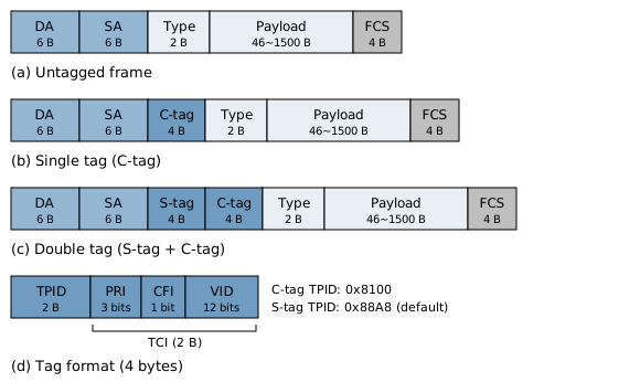
VLAN Frame Format
Supported Tag Layers
Up to two tag layers are recognized: the outer tag (S-tag, used for QinQ) and the inner tag (C-tag).
Nested tags of three or more layers are not supported.
Energy Efficient Ethernet (EEE)
EEE (Energy Efficient Ethernet, IEEE 802.3az) lets the link enter the Low Power Idle (LPI) state when idle and wake up quickly when there is data to send. EEE is disabled by default. To use it, auto-negotiation must be enabled, and both the PHY and the link partner must support EEE.
The LPI process on the line is as follows:

LPI States
Sleep: the local end notifies the peer that it is entering low power.
Quiet: signaling stops to save power, and a Refresh signal is sent periodically to keep the link alive.
Wake: when there is data to send, a wake signal is sent, and after the wake time the link returns to Active.
When to sleep and when to wake is determined by the specific policy, which can be chosen for the application scenario, as described below.
Sleep Policy
The sleep policy decides when the MAC requests to enter LPI. The default is “queue empty”.
Policy |
Condition to Enter LPI |
|---|---|
Queue empty (default) |
Request LPI when the transmit queue is empty. |
Low traffic |
Request LPI when the transmit traffic in the statistics window is below the configured traffic threshold. |
PAUSE frame received |
Request LPI when a PAUSE frame is received from the peer. |
The three policies can be combined. LPI is requested when any one of the conditions is met.
Wake Policy
The wake policy decides when the MAC leaves LPI and resumes transmission. The default is “any data”.
Policy |
Condition to Leave LPI |
|---|---|
Any data (default) |
Wake as soon as there is data in the transmit queue. |
Wake on threshold |
Wake only when the transmit queue reaches the threshold, or a frame larger than 512 bytes is waiting. Small packets wait in the queue, which increases latency but reduces the number of wake-ups. |
Scenario Selection
Scenario |
Sleep Policy |
Wake Policy |
Characteristics |
|---|---|---|---|
General networking, latency sensitive (recommended) |
Queue empty |
Any data |
Default configuration. Sleeps when idle and wakes immediately on data, giving the lowest latency. |
Continuous low-rate transmission, longer time in low power desired |
Low traffic |
Any data |
Sleeps when traffic is below the threshold, so LPI is entered more easily than with “queue empty”, but transmitted data may wait for the wake-up. |
Mostly bulk transfers, small-packet latency not a concern |
Queue empty |
Wake on threshold |
Fewer wake-ups, at the cost of higher small-packet latency. |
The peer or switch uses PAUSE frames for flow control |
Add “PAUSE frame received” to the policies above |
Same as above |
Enters low power together with the peer when it asks to pause transmission. |
Note
With bursty traffic the PHY switches frequently between Active and LPI, so measure the effect on latency and throughput. EEE is not recommended for applications with high throughput requirements.
The timing parameters and the traffic threshold normally keep their default values.
Loopback Test Configuration
The loopback test checks link connectivity. During debugging it is used to confirm that the MAC link and the external link are working. There are two modes, internal loopback (T2R) and external loopback (R2T):
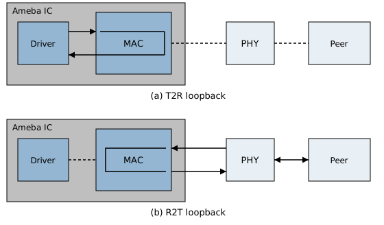
Loopback Test Modes
Mode |
Data Flow |
Purpose |
|---|---|---|
Internal loopback (T2R) |
Transmitted data returns to the receive path inside the MAC, without going through the PHY or cable. |
Check the TX/RX driver, descriptors, and interrupt handling. |
External loopback (R2T) |
The MAC sends the data received from the PHY back unchanged, with no software involvement. An external peer must send test frames and check the returned frames. |
Check the external path between the MAC, the PHY, the cable, and the peer. |
The loopback mode is configured when Ethernet is initialized and cannot be switched at run time. After testing, set it back to normal mode and re-initialize.
Descriptor and Buffer Configuration
The MAC sends and receives data through DMA. A descriptor is a small data structure in memory that passes the address, length, and status of each data buffer between the CPU and the DMA. The CPU only fills in descriptors, and the DMA moves the data. Transmit and receive each have a descriptor ring. Each descriptor in the ring corresponds to one data buffer, and the last descriptor wraps around to the first.
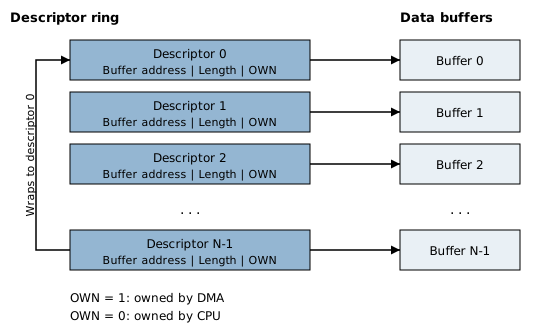
Descriptor Ring and Data Buffers
The ownership bit (OWN) in a descriptor shows who processes it. When OWN is 1 the descriptor belongs to the DMA and the CPU must not modify it. The DMA clears it after processing and returns the descriptor to the CPU. When a frame occupies several descriptors, flag bits mark which one is the first and which one is the last. In addition, on transmit, control bits enable hardware functions such as checksum and VLAN, and on receive the hardware returns status such as the checksum result and the frame type.
Each TX descriptor occupies 20 bytes of SRAM and each RX descriptor occupies 16 bytes. Each descriptor also corresponds to a 1536-byte data buffer, which can hold the largest standard frame including a VLAN tag.
The number of descriptors can be set manually in Menuconfig, separately for TX and RX. If not set manually, the default is 4 when IMG2 runs from Flash (XIP) and 8 when it runs from PSRAM. More descriptors consume more memory. Increasing the RX count helps absorb traffic bursts, but does not replace prompt RX processing and recycling.
Note
With the SDK’s LwIP Ethernet driver, the driver allocates, aligns, and recycles the descriptor rings and buffers and performs the cache maintenance. The application only decides the number of descriptors. When you implement TX/RX yourself, note the following:
Place the descriptor rings in non-cacheable SRAM, with the starting address aligned to 32 bytes.
The number of RX descriptors must be a power of two (for example 4, 8, 16, 32, 64), otherwise the build fails. The TX count has no such restriction.
A data buffer in cacheable memory must be aligned to the 32-byte cache line and occupy whole lines, must not share a cache line with other data, and needs DCache Clean and DCache Invalidate around DMA accesses.
Once a buffer is handed to the DMA, the CPU must not modify or reuse it until the descriptor is returned.
On receive, the MAC inserts 2 bytes of padding ahead of the frame data, so reserve space for it in the buffer.