CAN Protocol Layer
Protocol Frame Format Overview
The protocol layer defines the encapsulation format of data on the bus. The CAN protocol mainly includes the following frame formats:
Frame Type |
Main Purpose |
Transmission Timing/Constraint |
Key Features |
|---|---|---|---|
Data Frame |
Transmits actual data |
|
|
Remote Frame |
Requests data for a specific ID |
|
|
Error Frame |
Notifies global bus error |
|
|
Overload Frame |
Delays the next frame reception (gives receiver breathing time) |
|
|
Interframe Space |
Physically separates consecutive frames |
|
|
Data Frame
The Data Frame is the most common type used for data transmission between nodes on the CAN bus.
Standard Data Frames use an 11-bit identifier, formatted as follows:
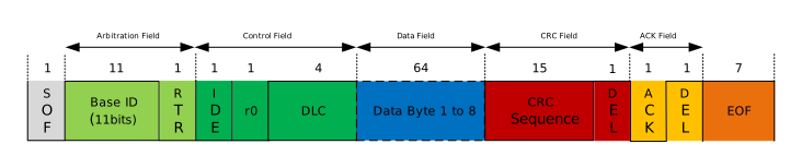
Standard Data Frame
Extended Data Frames use a 29-bit identifier (11-bit Base ID + 18-bit Extension ID) for larger networks, formatted as follows:

Extended Data Frame
Key Field Analysis
The frame structure starts with a dominant bit (Logic 0) and ends with consecutive recessive bits (Logic 1). A complete Data Frame consists of seven fields: Start of Frame, Arbitration Field, Control Field, Data Field, CRC Field, ACK Field, and End of Frame.
Field |
Composition/Bit Definition |
Technical Description |
|---|---|---|
Start of Frame (SOF) |
1 bit (Dominant) |
Identifies the start of the frame, used for hard synchronization. |
Arbitration Field |
ID, RTR, IDE, SRR |
|
Control Field |
DLC (4 bits), r0/r1 |
DLC: Data Length Code, indicates number of data bytes (0-8). r0/r1 are reserved bits. |
Data Field |
0-8 Bytes |
Payload, MSB first. |
CRC Field |
CRC Sequence (15 bits) + Delimiter |
Hardware calculates checksum. Delimiter is a recessive bit. |
ACK Field |
ACK Slot + Delimiter |
Sender sends recessive; receiver pulls low to dominant to acknowledge. |
End of Frame (EOF) |
7 bits (Recessive) |
Identifies the end of the frame, no bit stuffing. |
Remote Frame
Used by a receiving node to request data from a transmitting node. The main difference from a Data Frame is: RTR bit is Recessive (1) and there is no Data Field. Formats are shown in Standard Remote Frame and Extended Remote Frame.
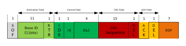
Standard Remote Frame
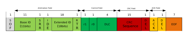
Extended Remote Frame
Error Frame
Sent when a node detects a bus error. It consists of an Error Flag (6 bits) and an Error Delimiter (8 bits). Figures Active Error Frame and Passive Error Frame show the two frame formats. Since different nodes may detect errors and send error frames at different time points, the error flags on the bus may superimpose, resulting in an error flag duration between 6 and 12 bits. Refer to Error Detection and Management for details.
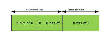
Active Error Frame
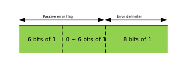
Passive Error Frame
Overload Frame
Sent when a receiving node is not ready to receive the next frame data, used to insert extra delay between frames. The format is as follows:
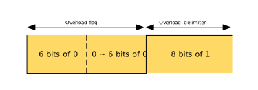
Refer to Sending Overload Frame for timing details.
Interframe Space
Used to separate Data Frames and Remote Frames. The format is as follows:
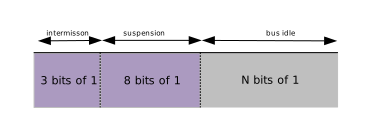
Data Frames and Remote Frames can be separated from any preceding frame (Data, Remote, Error, Overload) by inserting an Interframe Space.
Interframe Space cannot be inserted before Overload Frames and Error Frames.
Where:
Intermission: After the previous frame (EOF or Error Delimiter) ends, the bus must maintain a recessive level (1) for 3 bits.
Suspension: When an error occurs:
If a node is in Error Active state, after sending a frame and the 3-bit Intermission, it can immediately contend for the bus to send the next frame.
If a node frequently errors and enters Error Passive state, the protocol requires it to wait an additional 8 recessive bits (Suspension) after sending a frame.
Bus Idle: If the above phases are completed and there is still no data on the bus, it enters “Bus Idle” state. The bus remains recessive (1). Any node wishing to send data can pull the level low (0) at any time to start transmission (i.e., send SOF bit).
Bit Timing and Synchronization
CAN uses asynchronous serial communication, requiring both sender and receiver to agree on a baud rate. To solve clock drift and transmission delay issues, ISO 11898 defines a bit timing decomposition and synchronization mechanism based on Time Quantum (Tq).
Bit Decomposition
According to the ISO 11898-1 standard, the timing of one bit on the bus is divided into four segments:
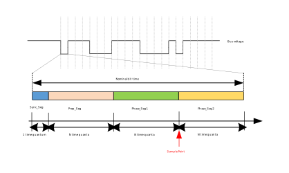
The minimum unit of a decomposed bit is the Time Quantum (Tq), with size prescaler/core clk, where core_clk is the CAN source clock input. A complete bit generally consists of 8-25 Tqs.
Synchronization Segment (Sync_Seg): Used to determine if the signal edge on the bus falls exactly within the Sync_Seg. If so, the communication node is synchronized with the bus.
Propagation Segment (Prop_Seg): Used to compensate for physical transmission delay on the lines and internal transceiver delay. Electrical signals take time to propagate. For example, during arbitration, if this time is not reserved, Node A might sample before its signal reaches Node B, causing a sampling error.
Phase Buffer Segment 1 (Phase_Seg1): Elastic buffer before sampling, located immediately before the sample point. If Sync_Seg of the current bit detects a late signal edge (after Sync_Seg), meaning the current bit arrived late, this segment is extended to prevent premature sampling.
Phase Buffer Segment 2 (Phase_Seg2): Elastic buffer after sampling. If Sync_Seg of the current bit detects an early signal edge, meaning the current bit ends too early, this segment is shortened so the next bit can be sampled correctly.
Sample Point is located at the end of Phase_Seg1. By controlling segment lengths, the sample point position can be shifted for accurate sampling.
The table below gives reference ranges for each segment.
Parameter |
Range |
Description |
|---|---|---|
Bit Rate Prescaler (Prescaler) |
1 ~ 32 |
Tq = prescaler / core_clk |
Sync_Seg |
1 Tq (Fixed) |
Synchronizes CAN nodes on the bus. |
Prop_Seg |
1 ~ 8 Tqs |
Compensates for physical delay in the network. |
Phase_Seg1 |
1 ~ 8 Tqs |
Compensates for edge phase errors; may be temporarily lengthened during synchronization. |
Phase_Seg2 |
2 ~ 8 Tqs |
Compensates for edge phase errors; may be temporarily shortened during synchronization. |
SJW |
1 ~ 4 Tqs |
Cannot be longer than either Phase Buffer Segment (Phase_Seg1/2). |
Communication Baud Rate
The communication rate of a CAN node is the inverse of the total Tq count for a single bit. For example, if the clock source is 40MHz and the prescaler is 2, a single Tq time is 0.05us. Assuming a single bit occupies 20 Tqs, the baud rate is:
Baud Rate = core_clk / (BRP × Total Tq) = 1000000 baud/s
Synchronization Process
The previously defined segment division for each data bit did not involve phase details. According to the ISO 11898 standard, synchronization is divided into:
Hard Synchronization: Only effective when a “Start of Frame (SOF)” signal exists.
Resynchronization: Effective for subsequent signals after SOF.
Both use the Sync_Seg segment for detection. The goal is to align the node’s internal Sync_Seg to encompass the signal edge.
Hard Synchronization
When Bus Idle ends, the first SOF signal arrives. If the receiving node detects the bus SOF edge outside its internal timing SS (Sync_Seg) range, it determines it is unsynchronized. The receiving node then forcibly resets its Bit Time counter, aligning its Sync_Seg to the falling edge of the SOF signal. Sampling can proceed correctly after synchronization.
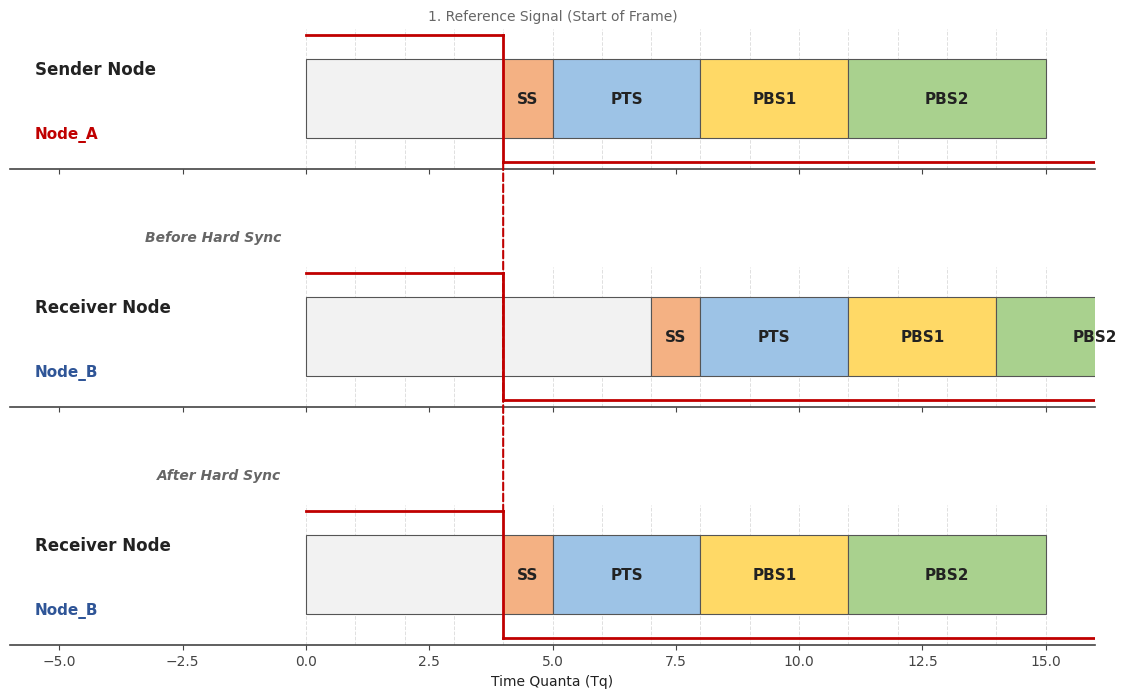
Hard Synchronization
Using Figure Hard Synchronization as an example:
Transmitting Node_A sends the SOF bit; the falling edge is in its SS segment.
Receiving Node_B finds its current SS segment is not synchronized with Node_A’s SOF SS segment. (Node_B’s SS segment occurred 5 Tqs earlier).
Node_B forcibly aligns its current SS segment to sync with the SOF SS segment.
Resynchronization
During frame transmission (except for SOF), resynchronization occurs upon detecting a recessive-to-dominant (high-to-low) edge. Based on the relative position of the bus edge and Sync_Seg, resynchronization is divided into:
Resynchronization for Phase Lead (as shown in Figure Resynchronization (Phase Lead)).
Transmitting Node_A is slower than Receiving Node_B. Node_A’s SS segment occurs when Node_B’s SS segment for the current bit occurred 2 Tqs ago.
Node_B extends PBS1 by 2 Tqs.
Node_A’s sample point for the current bit now syncs with Node_B’s.
Resynchronization for Phase Lag (as shown in Figure Resynchronization (Phase Lag)).
Transmitting Node_A’s SS segment occurs 2 Tqs before Receiving Node_B’s.
Node_B shortens its PBS2 segment.
This allows Node_B’s next bit to start 2 Tqs earlier, syncing the next bit’s sample point with Node_A.
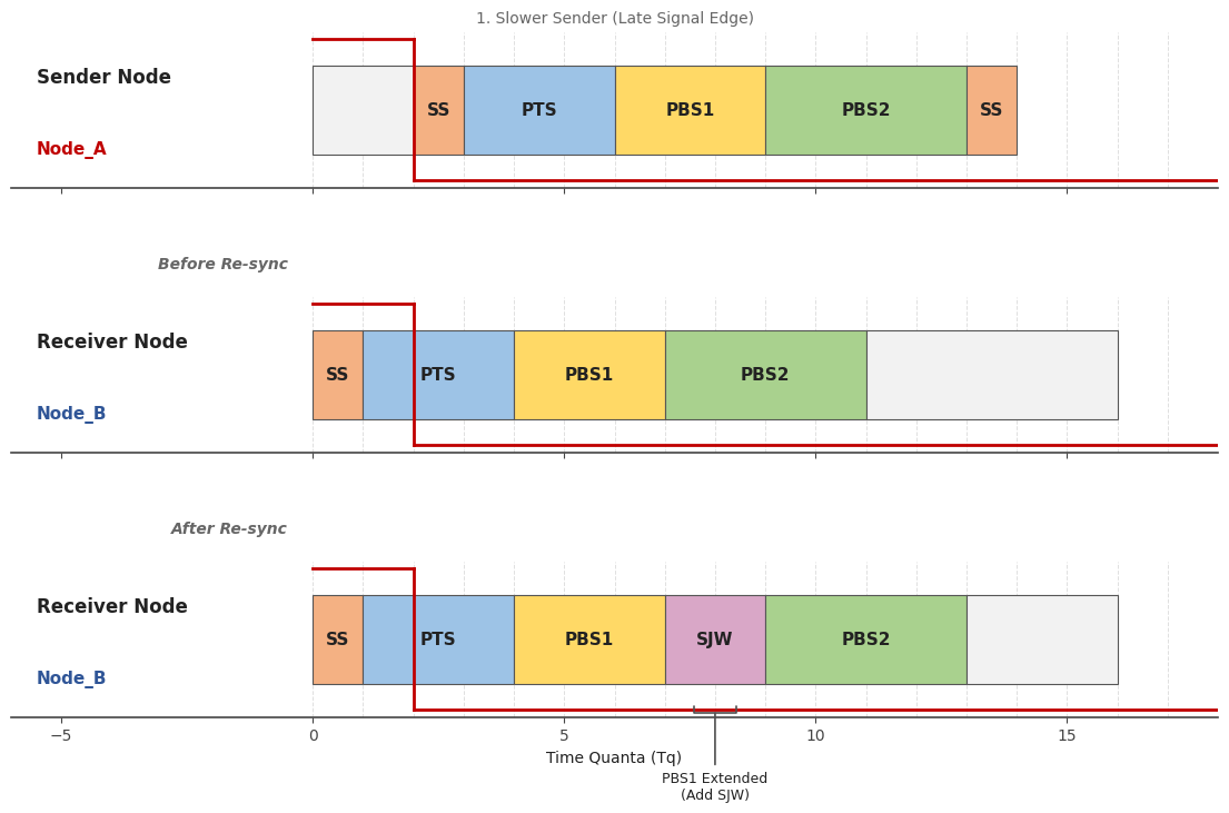
Resynchronization (Phase Lead)
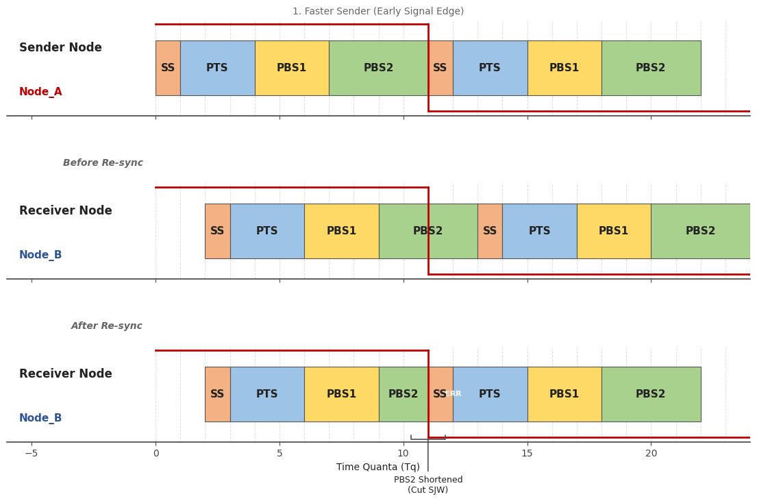
Resynchronization (Phase Lag)
The time duration by which Phase_Seg1 is increased or Phase_Seg2 is decreased during resynchronization is defined as SJW (Resynchronization Jump Width). A single synchronization cannot add or subtract more than the SJW duration. If needed, the controller adjusts via multiple small steps. A larger SJW allows the controller to absorb larger errors but may reduce communication speed/stability tolerance.