CAN Configuration
Clock Source Configuration
CAN relies on XTAL (40MHz) as the clock source. Users can call CAN_CoreClockSet() to select XTAL.
Baud Rate and Bit Timing Configuration
As mentioned, a CAN bus bit consists of four time segments. To simplify configuration, the CAN controller combines Prop_Seg and Phase_Seg1 into TSEG1, and refers to Phase_Seg2 as TSEG2.
Note
TSEG1 setting is the sum of Propagation Segment (Prop_Seg) and Phase Buffer Segment 1 (Phase_Seg1).
Taking Clock Source 40MHz, 1Mbaud/s rate, Sample Point at 80% as an example, the parameters are calculated as follows:
Sample Point Formula
Sample Point (%) = (Sync_Seg + TSEG1) / (Sync_Seg + TSEG1 + TSEG2) × 100%
Values satisfying the 80% ratio (4/5) include 8/10, 12/15, 16/20, 20/25.
The total Tq count for a single bit is:
Total Tq = Sync_Seg + TSEG1 + TSEG2
Typically, Total Tq is between 8 ~ 25. We can choose 10 or 20 for convenience.
Selecting Total Tq = 10:
Sync_Seg + TSEG1 = 8
Sync_Seg + TSEG1 + TSEG2 = 10
Thus, TSEG1 = 8 - 1 = 7 and TSEG2 = 10 - 7 - 1 = 2.
SJW is usually 1 ~ 4 Tqs and must not exceed the smaller of TSEG1 and TSEG2. In this example, setting it to 1 Tq is recommended.
Bit Timing Parameter Setting
Baud rate formula:
Baud Rate = core_clk / (BRP × Total Tq)
Given 1 Mbps rate, 40 MHz clock, and 10 Total Tqs, the prescaler (BRP) is 4.
Parameters can be configured as follows:
Parameter |
Phy Value |
Register |
Note |
|---|---|---|---|
Clock |
40 MHz |
XTAL as clock source |
|
BRP |
4 |
3 |
tq = 100ns |
NBT |
10 tq |
Nominal Bit Time |
|
TSEG1 |
7 tq |
6 |
PropSeg + PhaseSeg1 |
TSEG2 |
2 tq |
1 |
PhaseSeg2 |
SJW |
1 tq |
1 |
|
Result |
80% |
Sample Point (1+7)/10 = 80% |
In practice, users can directly call CAN_CalcBitTiming() to calculate the required parameters for the target baud rate.
3-Point Sampling
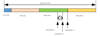
When 3-Point Sampling is enabled, the CAN controller samples the input signal at three different points separated by Tq, as shown below. The final logic level is determined by the majority. This effectively filters glitches and improves robustness.
Note
Generally recommended for low baud rates (below 125Kbps), where each Tq is longer, making the system more susceptible to glitches causing level shifts.
Message Tx/Rx Settings
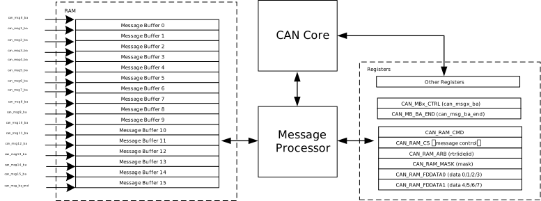
The CAN module manages message transmission and reception (including filtering) via Message Buffers (MB). CAN provides a set of registers as a common interface (referred to as RAM Interface) to manage message buffers.
Message Buffer Management
CAN features independent RAM space (352 × 32 bits), divided into 16 Message Buffers (MB0~MB15). By default, each buffer occupies 6 × 32 bits.
Capacity Config: Each buffer stores one message; size is independently configurable.
Address Allocation: Set the Base Address for each buffer. If MB0 Base Address is 0x0 and MB1 is 0x6, MB0 size is 6 × 32 bits.
Boundary: The effective range of the entire RAM can be specified.
Message Transmission and Reception
Transmission Flow
Select Buffer: Choose and enable a Message Buffer.
Fill Data: Write data, ID, DLC, and frame attributes (IDE, RTR) to the RAM Interface.
Configure Mode: Set to Transmit Mode.
Write Buffer: Write settings and data into the Message Buffer.
Status Update: Buffer status bits update automatically; interrupt triggers if enabled.
Reception Flow
Select Buffer: Choose and enable a Message Buffer.
Configure Filter: Set ID, Mask (MASK), IDE, and RTR bits in the RAM Interface to define expected message characteristics.
Configure Mode: Set to Receive Mode.
Write Buffer: Write settings into the Message Buffer.
Receive & Store: Upon receiving a frame and passing CRC, the processor scans all RX buffers for a filter match. If matched and error-free, the message is stored.
Status Update: Buffer status bits update automatically; interrupt triggers if enabled (user reads buffer in interrupt).
For CAN usage examples, refer to CAN example.
Buffer Priority
When multiple buffers meet Tx or Rx conditions simultaneously, hardware arbitrates based on buffer number (0-15):
Tx Priority: Lower number has higher priority (e.g., MB0 > MB1).
Rx Priority: Higher number has higher priority during matching (e.g., MB15 > MB0).
Message Filtering
ISO 11898 uses broadcast communication; there are no physical addresses. Nodes use Message Filtering to decide whether to accept data frames.
CAN allows configuring Receive Identifier (ID) and Acceptance Mask (MASK) for hardware-level filtering, reducing CPU load.
CAN Message Filter Settings
Receive All Messages
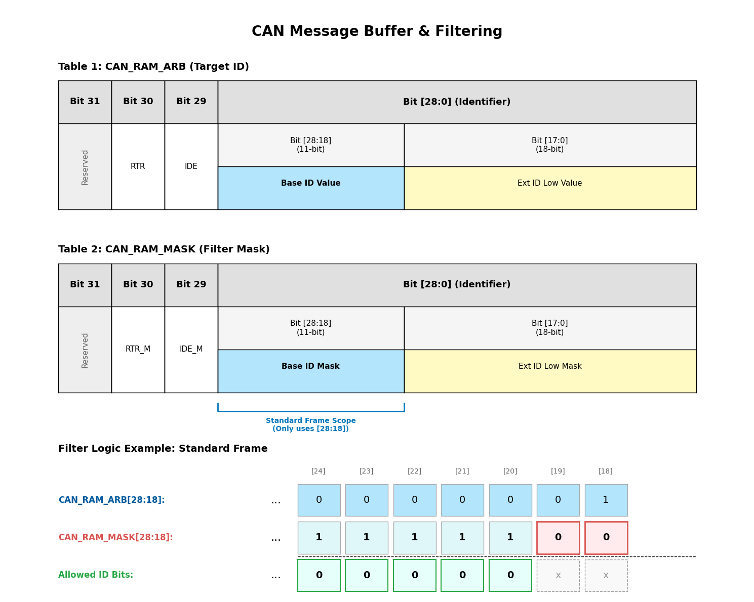
Set only ARB register (Receive ID) without configuring MASK. This implies ignoring ID bits, receiving all messages.
Receive Partial Messages
Set ARB and MASK registers. For example (Figure CAN Message Filter Settings), to filter standard frames: if ARB bits [28:18] are 0x1 and MASK bits [28:18] are 0x7FC, the lower 2 bits of the Standard ID are ignored. Base IDs 0x00, 0x01, 0x02, and 0x03 will be accepted.
Receive Specific Message
Set ARB register and configure all MASK bits to 1. This strictly matches the Receive ID; only messages with the exact ID are accepted.
Tip
Users can also set attributes in MASK to further match frame types:
RTR Attribute: Strictly match RTR setting in ARB (Data vs Remote Frame).
IDE Attribute: Strictly match IDE setting in ARB (Standard vs Extended Frame).
FIFO Mode
CAN supports merging the top 4 buffers (MB12~MB15) into a First-In-First-Out (FIFO) queue to enhance continuous reception capabilities.
Enable Mechanism: When FIFO is enabled, MB12~MB15 are reserved as FIFO storage space.
Filter Rule: The FIFO uniformly uses MB12’s configuration (ID, IDE, RTR, and Mask) as the filtering standard.
Highest Priority: The FIFO possesses the highest reception priority, strictly higher than normal reception buffers.
Overflow Handling: When the FIFO is full (MB12~MB15 all contain data) and a new message is received, the FIFO executes a rolling overwrite policy. The oldest received data (originally in MB12) is lost, data from MB13 moves to MB12, and so on, with the new message being stored in MB15. This action simultaneously triggers the overflow status flag.
Status Monitoring (CAN_FIFO_STS):
fifo_msg_empty: FIFO is empty.fifo_msg_full: FIFO is full (contains 4 unread frames).fifo_msg_overflow: Overflow (new frame received while full caused data loss).fifo_msg_lvl: Current number of messages in the FIFO.
Note
FIFO mode is enabled by default; users can disable it if not needed.
Receiving via DMA
CAN supports data reception via General Direct Memory Access (GDMA), supporting two flow control modes: GDMA as flow controller or CAN as flow controller.
When DMA is enabled, data in the Message Buffer (including ARB, CS, DATA) is transferred sequentially via GDMA to the target memory.
Configuration Process:
CAN Side:
In Rx DMA config register, set Rx DMA ownership and
rxdma_src_msize(usually 1).rxdma_owner = 0: Ownership belongs to GDMA.rxdma_owner = 1: Ownership belongs to CAN.
In the Message Buffer Control Register, enable DMA for that buffer.
In CAN Global Control Register, enable Rx DMA.
GDMA Side:
Configure source address, destination address, direction, block size, etc.
Note
Rx DMA transfer targets one Message Buffer per operation.
GDMA Source Burst Size must match
rxdma_src_msizeconfigured in CAN.
Automatic Retransmission
The ISO 11898-1 standard stipulates that if the controller fails to transmit a message successfully (i.e., no ACK received, error occurred, or arbitration lost), the controller can be configured to automatically retransmit the message. Once automatic retransmission is enabled, software only needs to write the transmission request once, and the hardware will automatically handle the subsequent retransmission logic. This process is typically transparent to the upper layer software (Application Layer).
Note
Setting a specific number of retransmission attempts is not supported.
Enable Automatic Retransmission
In the CAN module, the CAN_AutoReTxEn control bit determines whether to follow the standard ISO automatic retransmission process:
Enable (
CAN_AutoReTxEn= 1): Standard Mode. When transmission fails (e.g., arbitration lost or transmission error occurred), the hardware automatically re-participates in bus contention and attempts to send the same frame again until it is successfully sent or the node enters the “Bus Off” state due to excessive errors.Disable (
CAN_AutoReTxEn= 0): Single Shot Mode. The CAN controller attempts to send the message only once. Regardless of whether the transmission is successful (even if an error occurs or arbitration is lost), the hardware will not attempt to retransmit.
Scenarios Triggering Automatic Retransmission
When the automatic retransmission function is enabled, the following three scenarios will trigger a retransmission:
Arbitration Lost:
During the ID transmission phase, if the current node detects that the bus level is inconsistent with the level it is transmitting (it transmits recessive 1, but the bus is dominant 0), it indicates that a higher priority node is transmitting. The current node immediately stops transmitting and switches to the receiving state. Once the bus becomes idle, the hardware immediately attempts to transmit the message again.
Transmission Error:
If a Bit Error, Stuff Error, Form Error, or CRC Error is detected during transmission, the transmitting node sends an Error Frame to destroy the current transmission and retransmits the message when the bus becomes idle.
ACK Error:
The transmitting node sends a recessive level (1) in the ACK Slot, but does not detect a dominant level (0) on the bus. This means that no node on the bus has correctly responded to the message (i.e., replied with an ACK). The transmitting node determines this as an ACK Error, subsequently sends an Error Frame, and retransmits the message when the bus becomes idle.
Low Power Wake-up
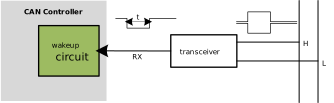
The CAN module supports low-power sleep modes, with the sleep type only supporting CG (Clock Gating) mode. In this mode, the module’s main clock is stopped, but the internally integrated wake-up detection circuit remains active.
CAN uses a low-frequency clock (OSC4M) to drive the wake-up circuit. When the CPU and CAN module enter sleep mode, the system must keep OSC4M enabled to support the monitoring function. For sleep mode configuration, please refer to Power Saving Configuration .
Wake-up Diagram
The workflow of the wake-up circuit is as follows:
Enable Conditions:
Wake-up detection is valid only when the CAN enters sleep mode (
can_sleep_enis set) and the wake-up filter function is enabled (can_wakepin_flt_enis set).Detection Principle:
The circuit continuously monitors the duration of the dominant level on the Rx pin and compares it with the preset threshold
can_wakepin_flt_lengthto determine if it is a valid wake-up signal. As shown in Wake-up Diagram, if the duration t of the dominant level (i.e., logic level 0 on the Rx pin) is greater than the set threshold (can_wakepin_flt_length/OSC4M), it wakes up the CAN module and the entire system.Trigger Action:
Wake-up: If the detected dominant level duration exceeds the preset threshold, the wake-up circuit generates a wake-up signal to reactivate the CAN module and the entire system.
Hold: If the dominant level duration does not reach the threshold, the module and system remain in sleep mode.
Note
Protocol frame content is irrelevant for wake-up: The dominant level that wakes up the CAN module comes from a valid protocol frame, but this frame cannot be received.
Transceiver must work normally during wake-up: Some transceivers may have standby/sleep modes. Ensure the transceiver is operating normally before attempting to wake up the CAN module.
Wake-up & Frame Loss:
Since it takes time for the system to recover from sleep and for the main clock to stabilize, the CAN module will inevitably miss the frame that triggered the wake-up. Whether subsequent data can be received depends on the sender’s retransmission mechanism:
If no other node on the bus sends an ACK:
The sending node determines transmission failure due to missing ACK. If its automatic retransmission mechanism is enabled, it will immediately retransmit the frame. By this time, the CAN module has completed wake-up initialization and can correctly receive this retransmitted message.
If other nodes on the bus send an ACK:
The sending node receives an ACK and considers the message sent successfully, so it will not retransmit. In this case, although the current node (CAN) is successfully woken up, it cannot receive the data of that frame (resulting in single frame loss).
Test Modes
Two test modes are available:
Silence Mode: Bus Monitoring Mode in ISO 11898-1. Used to analyze traffic without interfering. It receives all frames but sends nothing (no frames, no ACK).
Loopback Mode: Verifies CAN controller functionality.
External Loopback: Data frames are sent to the TX pin; protocol frames can be captured by an external analyzer.
Internal Loopback: Data frames transfer entirely within the CAN controller; nothing is sent externally.
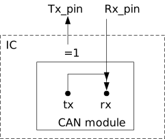
Silence Mode
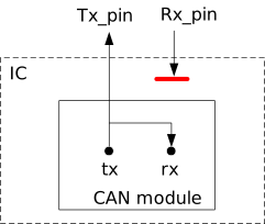
External Loopback Mode
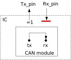
Internal Loopback Mode