CAN Physical Layer
Topology
As a protocol controller, the CAN module requires an external transceiver to convert logical levels to differential signals. The physical layer design directly determines the communication distance and anti-interference capability. Depending on the application scenario, CAN supports two typical network topologies:
High-Speed Closed-Loop Network (ISO 11898-2)
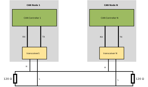
Suitable for high-speed (standard CAN up to 1Mbps), short-distance (<40m) communication. Both ends of the bus must be connected with 120Ω termination resistors to suppress signal reflection.
Low-Speed Open-Loop Network (ISO 11898-3)
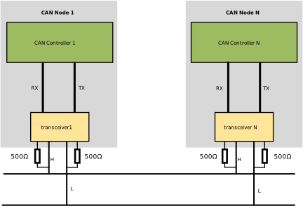
Suitable for low-speed (up to 125Kbps), long-distance (<1km) communication.
Physical Signals
The TX/RX signals between the CAN controller and the transceiver are normal logic levels, where 0 represents a low level and 1 represents a high level. The signals on the bus lines H/L from the transceiver use differential signal transmission.
When a CAN node needs to transmit data, the controller sends the binary code via TX to the transceiver. The transceiver converts this normal logic level into a differential signal and transmits it to the bus network via the differential lines H and L.
When a CAN node needs to receive data, the transceiver converts the differential signal received on H and L into a normal logic level and outputs it to the CAN controller via RX.
Differential signal transmission requires two signal lines. The voltage amplitudes on the two lines are the same but opposite in phase. Their difference is used to represent logic levels 0 and 1. The figure below shows a set of standard differential signals and their difference.
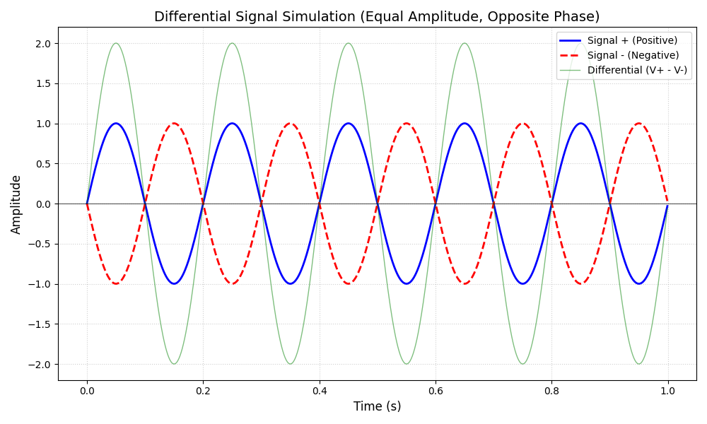
Compared to single-ended signal transmission, differential signal transmission has the following characteristics:
Strong Anti-Interference Ability: When noise interference occurs, the noise couples to both signal lines simultaneously. The final signal difference cancels out, suppressing external common-mode noise.
Low Electromagnetic Radiation: Since the signal lines are twisted pair, the magnetic field polarities are opposite, canceling out external radiation. This results in less interference with surrounding circuits and easier passing of EMC (Electromagnetic Compatibility) tests.
Precise Timing Positioning: Single-ended signal logic switching depends on a fixed reference voltage (e.g., Vcc/2), which is highly susceptible to power supply fluctuations. The logic switching point of differential signals is the crossing point of the two signal lines. The detection of the crossing point is unaffected by reference voltage drift, greatly reducing timing jitter.
No Common Ground Required: Single-ended signals must reference GND. Inconsistent reference voltages at both ends can easily lead to signal misjudgment. Differential signals only concern the voltage difference and do not require a common ground.
Note
The actual differential signal transmitted on the line is affected by the real electromagnetic environment, transmission distance, etc., causing deformation in signal shape, amplitude, and phase.
Differential Signal Specifications
The ISO 11898 standard specifies the differential signals as follows:
Signal |
Recessive (Logic 1) |
Dominant (Logic 0) |
||||
|---|---|---|---|---|---|---|
Min |
Typ |
Max |
Min |
Typ |
Max |
|
CAN_High (V) |
2.0 |
2.5 |
3.0 |
2.75 |
3.5 |
4.5 |
CAN_Low (V) |
2.0 |
2.5 |
3.0 |
0.5 |
1.5 |
2.25 |
High-Low Diff (V) |
-0.5 |
0 |
0.05 |
1.5 |
2.0 |
3.0 |
Signal |
Recessive (Logic 1) |
Dominant (Logic 0) |
||||
|---|---|---|---|---|---|---|
Min |
Typ |
Max |
Min |
Typ |
Max |
|
CAN_High (V) |
1.6 |
1.75 |
1.9 |
3.85 |
4.0 |
5.0 |
CAN_Low (V) |
3.10 |
3.25 |
3.4 |
0 |
1.0 |
1.15 |
High-Low Diff (V) |
-0.3 |
-1.5 |
/ |
0.3 |
3.0 |
/ |
Taking the ISO 11898-2 high-speed physical layer voltage specification as an example:
When representing Logic 1 (Recessive Level), the voltages on both H and L lines are 2.5V, with a voltage difference of 0V.
When representing Logic 0 (Dominant Level), the voltage on the H line is 3.5V, and the voltage on the L line is 1.5V, with a voltage difference of 2V.
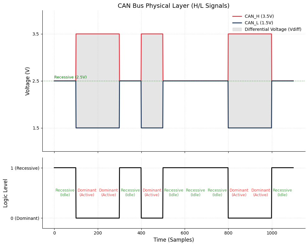
For example, when the transceiver wants to transmit a logic level 0 from the controller, it drives the H signal line to 3.5V and the L signal line to 1.5V, thereby outputting a dominant level (logic 0).
Tip
The dominant and recessive levels defined in ISO 11898 have a “Wired-AND” characteristic similar to the I2C bus (any node outputting a low level pulls the bus level low). If two CAN communication nodes transmit simultaneously, with one outputting a recessive level and the other a dominant level, the bus will present a dominant level (Logic 0). This is the fundamental mechanism for arbitration during node communication.
In the entire communication network, because the bus is shared, only one communication node can transmit signals at any given time (except during the arbitration phase where multiple nodes can transmit simultaneously), while other nodes can only receive. At the physical layer, CAN nodes, while sending the (TX) bit signal, read back the bus level in real time through RX (i.e., listen bit by bit) to achieve bus arbitration and error detection.