Error Detection and Management
When transmitting or receiving data on the bus, if a communication node detects an error, it actively initiates an Error Frame. As mentioned earlier, besides the 6-bit error flag, error flags may overlap by 0 to 6 bits. Before detailing Error Frames, one must understand Bit Stuffing, Error Types, and Error Handling mechanisms in ISO 11898.
Bit Stuffing
The ISO 11898 protocol relies on signal edge transitions for synchronization. If a data stream has a large number of consecutive identical logic levels (e.g., consecutive ‘1’s or ‘0’s), the signal will not toggle for a long time. The receiver will lose synchronization, causing sample point drift and communication errors. To solve this, bit stuffing rules are applied:
Sender Logic: When sending Data or Remote Frames, if 5 consecutive bits of the same polarity are detected within the SOF ~ CRC fields, a stuffing bit of the opposite polarity is automatically inserted.
Receiver Logic: When receiving Data or Remote Frames, if 5 consecutive bits of the same polarity are detected within the SOF ~ CRC fields during decoding, the subsequent bit (which must be of opposite polarity) is automatically removed (De-stuffed) to restore original data. If the 6th bit has the same level as the previous 5, it is treated as a Stuff Error.
The diagram below marks stuffing bits in orange:
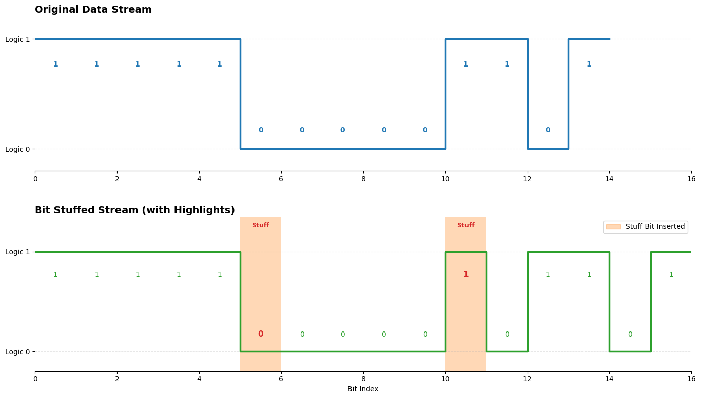
Bit Stuffing Diagram
Error Types
Common error types are listed below:
Error Type |
Description |
Detection Frame (Field) |
Error Frame Timing |
Detector |
|---|---|---|---|---|
Bit Error |
Detected when the monitored bus value differs from the bit value sent (excluding stuffing bits). |
|
Next Bit (Immediately starts sending Error Flag after the bit where error was detected) |
Sender |
Stuff Error |
Detected when 6 consecutive bits of the same level are observed in a field requiring bit stuffing. |
|
Next Bit (Immediately starts sending Error Flag upon detecting the 6th consecutive identical bit) |
Receiver |
CRC Error |
Detected when the calculated CRC result differs from the received CRC sequence. |
|
After ACK Delimiter (Starts sending at the first bit of EOF, i.e., after ACK Delimiter) |
Receiver |
Form Error |
Detected when a fixed-format bit field contains an illegal value. |
|
Next Bit (Exception: Form Error in CRC Delimiter is treated as CRC Error, sent after ACK Delimiter) |
Sender Receiver |
ACK Error |
Detected when the sender observes a recessive level in the ACK Slot (did not receive dominant ACK from receiver). |
|
After ACK Delimiter (Starts sending at the first bit of EOF, i.e., after ACK Delimiter) |
Sender |
Error Frame Timing:
Immediate Transmission (Next Bit):
Bit Error, Stuff Error, and Form Error (most cases) trigger an Error Frame immediately at the next bit. This ensures data consistency and prevents error propagation.
Delayed Transmission (After ACK Delimiter):
CRC Error and ACK Error trigger Error Frames after the ACK Delimiter.
CRC Error: Although the receiver calculates the error during CRC, it does not report it immediately. It sends an ACK (if format is correct) or not, and waits until after the ACK Delimiter to pull the bus low at the EOF stage. This avoids corrupting the ACK process for other nodes that might have received data correctly.
ACK Error: If the sender sees no acknowledgment (Recessive ACK Slot), it sends an Error Frame after the ACK Delimiter.
Note
Bit Errors do not occur during ID Arbitration, ACK Slot, or while sending a Passive Error Flag:
In Arbitration: Sending 1 but reading 0 is considered arbitration loss.
In ACK Slot: Sender sends Recessive 1 and reads 1 implies no ACK received (ACK Error).
Passive Error: Sending Passive Error Flag (6 recessive bits) but reading Dominant is not a Bit Error.
A dominant bit in the last bit of EOF triggers an Overload Frame, not an Error Frame.
Sender errors: Bit Error, Form Error, ACK Error.
Receiver errors: Stuff Error, Form Error, CRC Error.
Error Handling Mechanism
When a CAN node detects an error, it transitions between three states based on its internal error counters (TEC and REC).
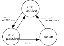
Error State Transition
Note
TEC: Transmit Error Counter
REC: Receive Error Counter
The table below summarizes entry conditions and behavior for each state.
Error State |
Entry Condition (Threshold) |
Error Flag Type |
Communication & Behavior |
|---|---|---|---|
Error Active |
TEC ≤ 127 AND REC ≤ 127 |
Active Error Flag (6 consecutive Dominant bits) |
|
Error Passive |
TEC > 127 OR REC > 127 |
Passive Error Flag (6 consecutive Recessive bits) |
|
Bus Off |
TEC > 255 |
None (Transmission Disabled) |
|
Error counters are updated at the first bit of the error flag. A single transmission/reception may meet multiple conditions, potentially adjusting the counter multiple times.
No. |
Trigger Condition |
TEC |
REC |
|---|---|---|---|
1 |
A receiver detects an error (except when the detected error was a bit error during the sending of an active error flag or an overload flag). |
— |
+1 |
2 |
A receiver detects a dominant bit as the first bit after sending an error flag. |
— |
+8 |
3 |
A transmitter sends an error flag. |
+8 |
— |
4 |
A transmitter detects a bit error while sending an active error flag or an overload flag. |
+8 |
— |
5 |
A receiver detects a bit error while sending an active error flag or an overload flag. |
— |
+8 |
6 |
Any node tolerates up to 7 consecutive dominant bits after sending an active error flag, passive error flag, or overload flag.
|
+8 |
+8 |
7 |
After the successful transmission of a frame (getting ACK and no error has been detected until EOF is finished). |
-1 if > 0; unchanged if = 0 |
— |
8 |
After the successful reception of a frame (reception without error up to the ACK slot and the successful sending of the ACK bit). |
— |
-1 if 1 ≤ REC ≤ 127; unchanged if = 0; set to between 119 and 127 if > 127 |
10 |
Bus-off recovery (detecting 128 occurrences of 11 consecutive recessive bits). |
Set to 0 |
Set to 0 |
There is an exception for the third item:
The transmitter is error-passive and detects an ACK error because of not detecting a dominant ACK and does not detect a dominant bit while sending its passive error flag.
The transmitter sends an error flag because a stuff error occurred during arbitration, whereby the stuff bit should have been recessive, and has been sent recessive but is monitored to be dominant.
Sending Error Frame
Non-overlapping Error Flags: Figure Non-overlapping Error Flags shows Node A detecting a “Bit Error” while transmitting, followed by Node B detecting a “Stuff Error” (due to 6 consecutive dominant levels). The error flags from Node A and Node B do not overlap.
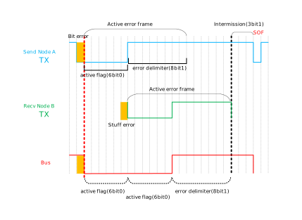
Non-overlapping Error Flags
Overlapping Error Flags: Figure Overlapping Error Flags shows Node A generating a “Bit Error” and Node B detecting a Stuff Error (6 consecutive dominant levels). The active error flags overlap by 2 bits, with 4 bits remaining.
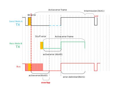
Overlapping Error Flags
Sending Overload Frame
The Overload Flag consists of 6 consecutive dominant bits (0). It destroys the transmission of other nodes on the bus, preventing them from sending messages normally, effectively delaying their transmission. An Overload Frame is transmitted in the following three cases:
Receiver Internal Not Ready: Due to processing speed or buffer limitations, the receiving node is not ready for the next frame. It sends an Overload Frame at the first bit of Intermission to forcibly extend the idle time.
Dominant Bit Detected at 1st or 2nd Bit of Intermission: A normal Intermission contains at least 3 consecutive recessive bits. Detecting a dominant bit in the first two implies a node transmitted early (timing error) or bus interference. The node sends an Overload Frame to handle this synchronization anomaly.
Dominant Bit Detected at 8th Bit (Last Bit) of Error/Overload Delimiter: The delimiter format is 8 consecutive recessive bits. If the last bit is dominant, it is treated as the next frame starting too early (or previous frame not ending correctly). This specific Overload Frame does not increment the error counter.
Dominant Bit Detected at Last Bit of EOF: Since the first 6 bits of EOF passed checks, the protocol deems current frame reception Valid, and handles this as an overload condition rather than a form error.
Note
Error Counters: Sending an Overload Frame is “harmless”; it does not increment the node’s TEC or REC.
Limit: To prevent permanent bus blocking, controllers typically limit the number of consecutive Overload Frames (usually max 2 frames delay).