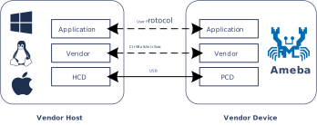
The USB Vendor Class (Vendor Specific) leverages the openness of the USB specification to allow for vendor-defined private protocols or requests, supporting developers in flexibly defining endpoint configurations and transfer types.
Ameba implements Vendor device functionality based on the underlying USB protocol stack, establishing a highly flexible and exclusive data channel.
The Host can interact with Ameba using private command sets and specific data formats via dedicated drivers or generic libraries (such as WinUSB), achieving customized control and functional expansion that transcends the limitations of standard device classes.
As a highly customizable USB device, Ameba can establish a dedicated control and communication channel between the host and the device through the Vendor interface, breaking through the functional limitations of standard device classes and enabling the following typical applications, such as:
Custom Protocol Communication: Define a private command set and data frame format for dedicated communication between devices and hosts (such as parameter configuration, fault diagnosis, and status inquiry).
Composite Device Function Extension: Based on standard classes (HID/CDC/UVC), a Vendor interface is added to implement additional control channels.
Secure Firmware Upgrade: Utilize a custom Vendor protocol to transmit firmware, enabling a private and secure upgrade mechanism.
The Vendor class does not have an officially unified USB class standard specification.
Its descriptor structure, command requests, and endpoint usage are all defined by the vendor and require a host-side driver or application for parsing.
The Vendor descriptor structure can contain standard device descriptors, configuration descriptors, device qualifier descriptors, other speed configuration descriptors, and string descriptors.
For detailed descriptor customization items, please refer to
Device Descriptor Customization
.
For Vendor devices, there are several key points to note regarding descriptors:
The class code bDeviceClass for Vendor devices is set to 0xFF/0x00. Hosts usually do not automatically load generic drivers (such as HID or MSC) but instead look for a dedicated driver matching the VID/PID.
      Device Descriptor
      |  bDeviceClass: 0xFF/0x00      (0xFF: Vendor Specific Class, 0x00: Interface-based Class)
      |  bDeviceSubClass: 0xFF/0x00   (Vendor Specific SubClass)
      |  bDeviceProtocol: 0xFF/0x00   (Vendor Specific Protocol)
      |  idVendor                     (Vendor ID, e.g. 0x0BDA is for Realtek)
      |  idProduct                    (Product ID)
      |  ...
The interface class code bInterfaceClass can be set to 0xFF to indicate a custom function class. Functional differentiation in composite devices typically occurs at the interface level.
  Interface Descriptor
  |  bInterfaceClass: 0xFF      (0xFF: Vendor Specific Class)
  |  bInterfaceSubClass         (Vendor Specific SubClass)
  |  bInterfaceProtocol         (Vendor Specific Protocol)
  |  ...
For example: A composite device has both standard MSC functionality and Vendor custom functionality.
Although string descriptors are not unique to the Vendor specification, in Vendor requests, string descriptors are often used to convey serial numbers (iSerialNumber) or specific firmware version information.
For example: The three fields iManufacturer/iProduct/iSerialNumber in the device descriptor are set to 1, 2, 3 respectively.
Device Descriptor
├── iManufacturer : 1  ──┐
├── iProduct      : 2  ──┤ (Index)
├── iSerialNumber : 3  ──┘
│
└── USB String Table
    │
    ├── String Descriptor     (Index 0: Must be read first!)
    │   └── LANGID Code Array (Language ID Array)
    │       └── 0x0409        (English - United States)
    │
    ├── String Descriptor     (Index 1: Pointed by `iManufacturer` index)
    │   └── "Realtek Semiconductor Corp." (Unicode)
    │
    ├── String Descriptor     (Index 2: Pointed by the `iProduct` index)
    │   └── "Realtek USB Vendor Device" (Unicode)
    │
    ├── String Descriptor      (Index 3: Pointed by the `iSerialNumber` index)
    │   └── "00E04C000001" (Unicode)
    │       ├── Funtion 1: Distinguish devices (Instance ID)
    │       └── Funtion 2: Function binding of USB composite device
    │
    └── String Descriptor     (Index 4/5/6/...: Optional/Customizable)
    │   ├── "FW_Ver_1.0"      (Firmware version information)
    │   └── "MAC_ADDR_..."    (Network Configuration)
    |
    │    ...
iSerialNumber: For Vendor devices, it is strongly recommended to implement this string and ensure the string value is unique.
Importance: For Vendor devices, if there is no serial number string, Windows hosts may consider it a new device and reload the driver every time the device is plugged into a different USB port.
Uniqueness: Ensure that the serial number of each chip is different, otherwise two devices of the same model plugged in simultaneously may conflict.
For Vendor devices, besides the conventional Manufacturer/Product names, using iSerialNumber for device identification is a high-frequency and critical usage.
Custom Strings: For Vendor devices, because there are no standard class restrictions, vendors often utilize unused string indices to pass firmware information or configurations.
Scenario A: Firmware Version Number
Index 4 can be defined as the firmware version string (e.g., “FW_Ver_1.0”).
Host mass production tools do not need to send complex Vendor requests; they can directly send the standard request GET_DESCRIPTOR (String, Index=4) to read the version number. This is very efficient during factory testing.
Scenario B: MAC Address (Commonly used in Network Cards)
For USB network cards, the MAC address is usually stored in eFuse or Flash.
Some firmware implementations will convert the MAC address into an ASCII string and place it in iSerialNumber, or in a dedicated custom index for upper-layer applications to read.
The USB protocol divides control request types into three categories:
Standard: Universal commands that all USB devices must support (e.g., GET_DESCRIPTOR, SET_ADDRESS).
Class: Commands defined by specific device classes (e.g., GET_REPORT for HID class, Bulk-OnlyReset for MSC class).
Vendor: This is the space left by USB-IF for vendors to use freely. As long as the host and device agree, any command can be defined (e.g., read/write registers, download firmware, enter factory mode, etc.).
All control transfers start with an 8-byte SETUP packet. Bits[6:5] of the first byte bmRequestType in the SETUP packet determine whether it is a Vendor request:
Bit Position
Field Name
Description & Values
Bit 7
Direction
0: Host to Device (OUT)
1: Device to Host (IN)
Bit 6..5
Request Type
00: Standard
01: Class
10: Vendor
11: Reserved
Bit 4..0
Recipient
00000: Device
00001: Interface
00010: Endpoint
00011: Other
When developing Vendor requests, special attention should be paid to the following key points to ensure the device responds correctly to control requests from the host:
Request Type Check: When processing the SETUP packet, the device must parse the bmRequestType field and confirm that its Type field is 10(i.e.,Vendortype).
Avoid Request Value Conflict: To prevent confusion between custom bRequest values and USB standard requests (e.g., 0x06: GET_DESCRIPTOR), it is recommended to maintain a clear request value definition table to ensure all custom requests have unique and clear identifiers.
Data Direction Control: Strictly adhere to Bit 7 (i.e., the Direction bit) of bmRequestType. If the host sends an OUT request but wLength > 0 and Bit 7 is IN, it may cause a device STALL or bus error; therefore, ensure direction consistency.
Endpoint Usage Specification: All Vendor requests are transmitted via the control endpoint by default, so the implementation should ensure that the control request processing logic is correctly bound to that endpoint.
Application Scenarios for Vendor Requests
Vendor requests allow users to flexibly implement proprietary configuration, state management, and data flow control for devices via custom control transfer commands.
For example, the following three application scenarios:
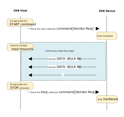
High-Performance Streaming:
High-Performance Streaming
This scenario is suitable for high-bandwidth, continuous data transmission applications, such as high-speed data acquisition instruments.
Working Mechanism:
Control Channel (Vendor Request): Used for sending low-frequency commands such as start/stop controls and parameter configuration.
Data Channel (BULK IN): Continuously and efficiently reports data to the host via bulk endpoints.
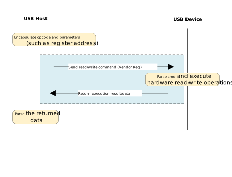
Command-Response Model:
Command-Response Model
This scenario is suitable for lightweight control applications, such as USB to GPIO/I2C/SPI bridges and device parameter configuration tools.
Working Mechanism:
Control Channel (Vendor Request): All operations are completed on EP0.
Command as Request: Directly utilizes the bRequest and wValue fields in the SETUP packet to carry opcodes and parameters, without occupying additional endpoint resources.
Control Transfer Atomicity: Each interaction is a complete control transfer transaction, consisting of three stages: Setup, Data (optional), and Status.
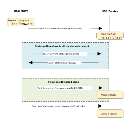
Private Firmware Update:
Private Firmware Update
This scenario combines the flexibility of control transfers with the high throughput of bulk transfers to implement device OTA (Over-the-Air) or DFU (Device Firmware Upgrade) functions via custom protocols, featuring state machine management and reliability verification mechanisms.
Working Mechanism:
Control Channel (Vendor Request): Responsible for sending critical control commands (such as Flash erase, status inquiry, verification, reset) to ensure process controllability.
Data channel (BULK OUT): Responsible for transmitting large blocks of firmware binary data, enhancing writing efficiency.
This driver implements a generic USB Vendor Class custom device. It is not affiliated with any standard USB classes (such as HID, MSC), but provides a flexible basic framework that allows developers to customize the transmission protocol.
The drive architecture adopts a layered design, consisting of three core levels from bottom to top:
Core Driver Layer: Responsible for handling low-level hardware interrupts and processing standard USB protocols.
Vendor Class Driver Layer (core implementation of this driver): responsible for managing endpoints, assembling descriptors, and handling transmission processing.
User Application Layer: Implement specific business logic. Interact with the Vendor class driver layer by registering the callback struct usbd_vendor_cb_t.
When designing a Vendor device, developers should plan reasonably according to actual application requirements (such as data throughput, real-time requirements) and the limitations of chip hardware resources (refer to
Hardware Features
).
Select the endpoint type according to the specific data transmission scenario:
Scenario
Recommended Endpoint
Data Integrity
Real-time (Latency)
Typical Application
Command & Status Control
Control
High (Retransmit)
Medium
Parameter setting, version retrieval
High Throughput Data
Bulk
High (Retransmit)
Low (No guarantee)
Firmware upgrade, file transfer, logging
Low Latency Events
Interrupt
High (Retransmit)
High (Fixed)
Keypress, alarm, status synchronization
Audio/Video Stream
Isochronous
Low (Packet Loss)
Very High (Constant)
Microphone, camera
Note
Avoid using Interrupt transfers for large data: Although high-speed mode allows interrupt endpoints to have large throughput, they use reserved bandwidth. Excessive occupation will exhaust the periodic bandwidth of the bus.
Note the non-real-time nature of Bulk transfers: Bulk transfers have the lowest priority in USB bus arbitration. Although extremely fast when the bus is idle, they may face scheduling delays of tens of milliseconds when busy. If the device requires hard real-time response (e.g., <2ms), please use Interrupt transfers.
Number and Direction of Endpoints: The number and direction of endpoints supported by the chip are fixed.
For example: The
RTL8721F
chip supports 5 IN and 5 OUT endpoints in addition to EP0.
EP0: INOUT
EP1: IN
EP2: INOUT
EP3: INOUT
EP4: IN
EP5: OUT
EP6: INOUT
EP7: OUT
FIFO Size: The receive and transmit buffers of the endpoints in the chip are configurable but have maximum limits. Ensure that the endpoint buffer size can accommodate at least one MPS length data packet.
For example: Hardware configuration of the
RTL8721F
chip in device mode.
In this example, besides EP0, the Vendor device includes a set of different endpoint types with opposite directions: BULK IN & BULK OUT, ISOC IN & ISOC OUT, INTR IN & INTR OUT.
Taking the
RTL8721F
chip as an example, the following explains the endpoint selection and DFIFO configuration process:
Hardware Resource Assessment: First, confirm that the hardware endpoint count can satisfy the requirements of the 3 groups (6 endpoints) of non-control endpoints mentioned above.
MPS (Max Packet Size) Setting
The FIFO size must accommodate at least one MPS transmission for the endpoint. Assuming hardware FIFO space permits, it is recommended to set the MPS to the maximum value allowed by the USB specification to improve throughput:
Bulk (High-Speed): 512 Bytes
Interrupt (High-Speed): 1024 Bytes
Isochronous (High-Speed): 1024 Bytes
DFIFO Allocation Strategy
Based on the hardware characteristics of the
RTL8721F
chip:
TX FIFO (Dedicated Transmit Buffer): Each IN endpoint has an independent transmit buffer.
RX FIFO (Shared Receive Buffer): All OUT endpoints share the same receive buffer.
DMA Requirement: In DMA mode, 1 DWORD (4 Bytes) of buffer space must be reserved for each endpoint.
Recommended Allocation Logic:
Transmit Buffer: Allocate sufficient space for each enabled IN endpoint based on the MPS values above.
Receive Buffer: Allocate all remaining available space to the RX FIFO to ensure stability during data reception.
Formula: RX FIFO Size = Total FIFO Space - Σ(TX FIFO config values of enabled IN endpoints) - Σ(1 DWORD reserved per endpoint)
The final suitable set of endpoints and DFIFO configuration is determined as follows:
/* Vendor Device Endpoint Address */#define USBD_VENDOR_BULK_IN_EP 0x86U /* EP6 for BULK IN */#define USBD_VENDOR_BULK_OUT_EP 0x03U /* EP3 for BULK OUT */#define USBD_VENDOR_ISOC_IN_EP 0x82U /* EP2 for ISOC IN */#define USBD_VENDOR_ISOC_OUT_EP 0x02U /* EP2 for ISOC OUT */#define USBD_VENDOR_INTR_IN_EP 0x84U /* EP4 for INTR IN */#define USBD_VENDOR_INTR_OUT_EP 0x05U /* EP5 for INTR OUT *//* Vendor Device DFIFO config */staticusbd_config_tvendor_cfg={/* DFIFO total 1024 DWORD, resv 12 DWORD for each EP’s DMA addr and IN EP0 with fixed 32 DWORD */.ptx_fifo_depth={16U,256U,32U,256U,128U,},// For IN EP: 1,2,3,4,6.rx_fifo_depth=292U,// All remaining fifo space is allocated to RX};
Vendor class devices adhere to the USB 2.0 standard descriptor architecture. Developers need to focus on configuration descriptor adaptation for multi-rate support and compliance settings for endpoint parameters.
The protocol stack supports descriptor customization; please refer to
Device Descriptor Customization
.
The complete set of Vendor Device Descriptors includes:
Device Descriptor: The root node, defining identity information such as VID/PID.
Configuration Descriptor Collection: Includes configuration, interface, and endpoint descriptors.
Multi-rate Support Descriptors (Optional): Device Qualifier Descriptor and Other Speed Configuration Descriptor.
String Descriptors (Optional): Provide text information such as manufacturer, product name, and serial number.
Regardless of the speed at which the device operates, typically only one common device descriptor needs to be maintained.
Key Field Settings:
bDeviceClass: Set to 0xFF (vendor-defined)/0x00 (class defined in interface descriptor).
bMaxPacketSize0: Controls the maximum packet size for endpoint 0, which is typically set to 64 by default.
idVendor/idProduct: Vendor ID and Product ID.
Example:
Standard Device Descriptor
├── bLength            : 1 byte   → Size of the descriptor (18 bytes)
├── bDescriptorType    : 1 byte   → 0x01 (DEVICE)
├── bcdUSB             : 2 bytes  → USB Specification Release Number (0x0200 = USB 2.0)
├── bDeviceClass       : 1 byte   → 0x00 (Class defined at Interface level)
├── bDeviceSubClass    : 1 byte   → 0x00
├── bDeviceProtocol    : 1 byte   → 0x00
├── bMaxPacketSize0    : 1 byte   → Max Packet Size for Control Endpoint 0 (64 bytes)
├── idVendor           : 2 bytes  → Vendor ID (VID)
├── idProduct          : 2 bytes  → Product ID (PID)
├── bcdDevice          : 2 bytes  → Device Release Number
├── iManufacturer      : 1 byte   → Index of string descriptor describing manufacturer
├── iProduct           : 1 byte   → Index of string descriptor describing product
├── iSerialNumber      : 1 byte   → Index of string descriptor describing the device's serial number
└── bNumConfigurations : 1 byte   → Number of possible configurations (1)
Configuration Descriptor and Multi-speed Adaptation
If the device is designed to support only one speed (e.g., Full Speed only), only the configuration set corresponding to that speed needs to be defined.
If the device needs to support both Full Speed and High Speed, parameters must be dynamically adapted according to the connection speed.
Developers need to define two sets of configuration descriptors in the code and return the corresponding set based on the actual speed during enumeration:
High Speed Configuration Descriptor Set: Used when the device enumerates as High Speed.
Full Speed Configuration Descriptor Set: Used when the device enumerates as Full Speed.
Note
When writing these two sets of descriptors, the wMaxPacketSize and bInterval fields in the endpoint descriptors must be strictly adjusted for the current speed.
Using Full Speed parameters in High Speed mode (or vice versa) will lead to enumeration failure or serious transmission performance issues.
Max Packet Size (wMaxPacketSize)
According to the USB 2.0 specification, the maximum packet size limits for endpoints differ at different speeds. The maximum packet size for each endpoint needs to be configured reasonably based on the actual bandwidth requirements of the application.
Device Qualifier & Other Speed Configuration Descriptors
If the device is designed to support only one speed mode, these two descriptors do not need to be implemented.
If the device is designed to support both Full Speed and High Speed modes, these two descriptors must be implemented to inform the host “what capabilities the device would have if it were operating at the other speed”:
Device Qualifier Descriptor: Structure is similar to the Device Descriptor but does not contain static identity information like VID/PID (which is speed-independent). It describes basic information about the device at the “other speed” (e.g., bMaxPacketSize0 at that speed).
Other Speed Configuration Descriptor: Describes the complete configuration tree of the device at the “other speed”.
Device Qualifier Descriptor
Focus on the following key fields of the device at the other speed:
bMaxPacketSize0: Defines the maximum packet size for endpoint 0 at the other speed.
bNumConfigurations: Defines the number of configurations supported at the other speed.
Example:
Device Qualifier Descriptor
├── bLength            : 1 byte   → Size of the descriptor (10 bytes)
├── bDescriptorType    : 1 byte   → 0x06 (DEVICE_QUALIFIER)
├── bcdUSB             : 2 bytes  → USB Specification Release Number (0x0200 = USB 2.0)
├── bDeviceClass       : 1 byte   → 0x00
├── bDeviceSubClass    : 1 byte   → 0x00
├── bDeviceProtocol    : 1 byte   → 0x00
├── bMaxPacketSize0    : 1 byte   → Max Packet Size for other speed (64 bytes)
├── bNumConfigurations : 1 byte   → Number of other-speed configurations (1)
└── bReserved          : 1 byte   → Reserved for future use (0x00)
Note
If the device enumerates as High Speed but does not provide a Device Qualifier Descriptor, Windows may report an error or run in degraded mode.
Other Speed Configuration Descriptor
The Device Qualifier Descriptor is just the entry point; the host will subsequently request the Other Speed Configuration Descriptor. At this point, the driver logic should execute a “Cross Return” strategy:
If currently running in High Speed mode, when the host asks about the “other speed”, return the Full Speed configuration descriptor set.
If currently running in Full Speed mode, when the host asks about the “other speed”, return the High Speed configuration descriptor set.
This device adheres to the USB 2.0 standard descriptor architecture and supports both Full Speed and High Speed. Below is an example of the device descriptor topology:
Device Descriptor
└─ USB Version 2.00 (Vendor Specific)

Configuration Descriptor
  └─ Interface (IF 0, Alt 0)
     ├─ Endpoint: BULK OUT, maxpkt=0x0200 (512 bytes)
     ├─ Endpoint: BULK IN, maxpkt=0x0200 (512 bytes)
     ├─ Endpoint: INTR OUT, maxpkt=0x0400 (1024 bytes)
     ├─ Endpoint: INTR IN, maxpkt=0x0400 (1024 bytes)
     ├─ Endpoint: ISOC OUT, maxpkt=0x0400 (1024 bytes)
     └─ Endpoint: ISOC IN, maxpkt=0x0400 (1024 bytes)

Device Qualifier Descriptor
└─ USB 2.0

Other Speed Configuration Descriptor
  └─ Interface (IF 0, Alt 0)
     ├─ Endpoint: BULK OUT, maxpkt=0x0040 (64 bytes)
     ├─ Endpoint: BULK IN, maxpkt=0x0040 (64 bytes)
     ├─ Endpoint: INTR OUT, maxpkt=0x0040 (64 bytes)
     ├─ Endpoint: INTR IN, maxpkt=0x0040 (64 bytes)
     ├─ Endpoint: ISOC OUT, maxpkt=0x03FF (1023 bytes)
     └─ Endpoint: ISOC IN, maxpkt=0x03FF (1023 bytes)

USB String Table
  ├── String Descriptor    (Index 0: Language ID Array)
  ├── String Descriptor    (Index 1: Manufacturer String)
  ├── String Descriptor    (Index 2: Product String)
  └── String Descriptor    (Index 3: SerialNumber String)
In the logical design, although the descriptor example defines only one interface, the interface is functionally divided into two modules: a Control Module responsible for command interaction and a Data Module responsible for business payload transmission.
Control Module
Responsible for command interaction, status management, and the enumeration process. It is based on the default bidirectional control endpoint EP0, therefore it does not consume endpoint resources in the interface descriptor.
Enumeration and Status Reporting: Responds to standard requests to complete device identification and configuration.
Vendor Requests: Supports issuing custom commands via control transfers (e.g., entering test mode, reading/writing registers).
Data Module
Responsible for full-rate data throughput and verification. It contains three sets of endpoints, providing the three non-control transfer types of the USB protocol.
Bulk Transfer: 1 pair of IN/OUT endpoints, used for non-periodic, large-block data transmission and loopback verification requiring high data integrity.
Interrupt Transfer: 1 pair of IN/OUT endpoints, used for periodic, low-latency small data transmission (e.g., status polling) and loopback verification.
Isochronous Transfer: 1 pair of IN/OUT endpoints, used for stream data transmission (e.g., audio/video streams) and loopback verification requiring high real-time performance and allowing minor packet loss.
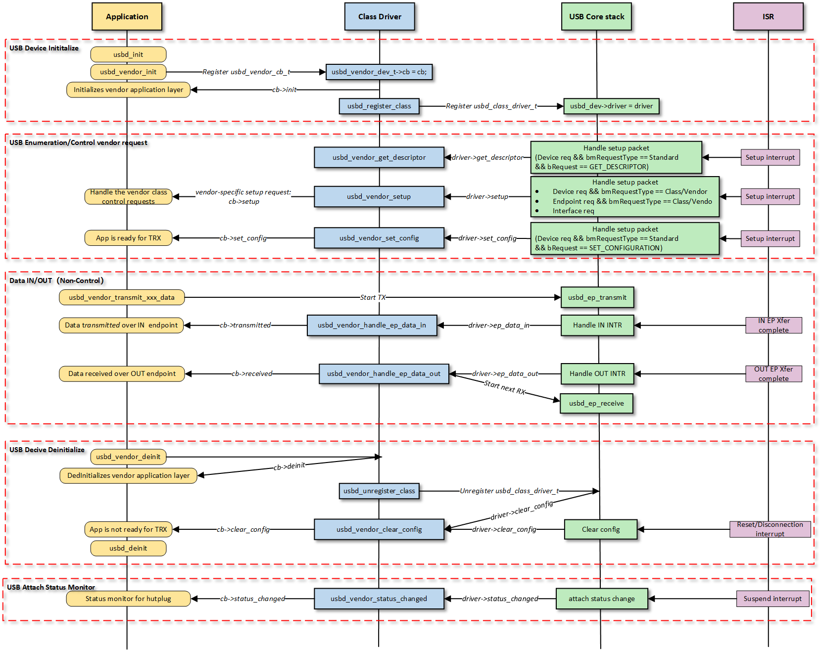
The USB Class Driver is typically divided into two layers: the Core Layer (handles hardware interrupts, standard enumeration, and state machines) and the Class Driver Layer (handles specific business logic, such as HID, MSC, and Vendor).
Note
The figure above illustrates the execution flow of callback functions at different levels and does not list all calling scenarios.
Class Driver Callback Functions
The class driver needs to define a standard usbd_class_driver_t structure. This serves as a unified entry point registered with the USB Core and is the primary method for the Core layer to notify the Class layer that “an event has occurred.”
get_descriptor: Called back during the enumeration process to obtain descriptors.
Setup: Called when an EP0 SETUP packet is received; it must determine if this is a Vendor request.
set_config: Traverses and initializes all endpoints and resources, and prepares to receive data.
clear_config: Traverses and releases all opened endpoints and resources.
sof: Called when an SOF interrupt occurs, used for processing logic with strict timing requirements.
ep0_data_in: Called after data is successfully sent to the host during the Control Transfer DATA IN stage.
ep0_data_out: Called after data is received from the host during the Control Transfer DATA OUT stage.
ep_data_in: Called after data is successfully sent to the host (Transmission Complete Interrupt).
ep_data_out: Called after data is received from the host (Reception Complete Interrupt).
Application Layer Callback Functions
The Vendor Class driver defines a callback structure usbd_vendor_cb_t facing the application layer.
This is implemented by the user layer, and generally, the following can be selectively implemented:
Callback
Description
deinit
Called when the class driver is de-initialized. Used to release
application-related resources.
setup
Called during the setup or data stage of a control transfer. Used to handle
application-specific control requests.
set_config
Called within the class driver’s set_config callback. Used to notify the
application layer that the class driver is ready.
status_changed
Called when the USB connection status changes. Used by the application layer to
handle USB hot-plug events.
sof
Called when an SOF interrupt is received. Used by the application layer for
clock synchronization handling.
transmitted
Called when an IN transfer completes. Used by the application layer to
asynchronously obtain the IN transfer status.
received
Called when an OUT transfer completes. Used by the application layer to
asynchronously obtain the OUT transfer status.
Example of Vendor Class Driver Application Layer Callbacks:
The usbd_vendor_init function is the top-level function used to initialize the Vendor device. Its core responsibilities are allocating endpoint resources, configuring endpoint parameters, and registering the class driver.
Define Device Instance
Define a globally unique Vendor device instance pointer usbd_vendor_dev, and separately define pointers to its internal endpoint structures and callback functions.
Example:
typedefstruct{usb_setup_req_tctrl_req;// Save control request for control transfer DATA OUT process.usbd_ep_tep_bulk_out;// BULK OUT endpoint.usbd_ep_tep_bulk_in;// BULK IN endpoint.// Other endpoint if exist.usb_dev_t*dev;// USB device core.usbd_vendor_cb_t*cb;// User callback.u8alt_setting;// Record the current interface alternate setting.}usbd_vendor_dev_t;/* 1. Vendor Device */staticusbd_vendor_dev_tusbd_vendor_dev;
Endpoint Parameter Initialization
Set the endpoint address, type, and allocate a buffer for it.
In DMA mode, ensure the endpoint transfer buffer address is aligned with the Cache line (e.g., 4-byte or 32-byte alignment, depending on the hardware platform).
Allocate at least one MPS (Max Packet Size) of space for the OUT endpoint’s receive buffer.
For OUT endpoints, specify the transfer length.
Since reception needs to be prepared in advance, set the transfer length; the length should not exceed the receive buffer size.
For periodic endpoints (Interrupt/Isochronous), set the polling interval binterval.
Example:
/* 2. Initialize Endpoint, such as Bulk OUT */usbd_vendor_dev_t*cdev=&usbd_vendor_dev;usbd_ep_t*ep_bulk_out=&cdev->ep_bulk_out;ep_bulk_out->addr=USBD_VENDOR_BULK_OUT_EP;ep_bulk_out->type=USB_CH_EP_TYPE_BULK;ep_bulk_out->xfer_len=USBD_VENDOR_BULK_BUF_SIZE;ep_bulk_out->xfer_buf=(u8*)usb_os_malloc(USBD_VENDOR_BULK_BUF_SIZE);
Execute User Callback Initialization
If a user init callback function is registered, call it. This gives the upper-layer application a chance to execute application-specific initialization logic.
Example:
/* 3. Execute User Init Callback */if(cb!=NULL){cdev->cb=cb;if(cb->init!=NULL){ret=cb->init();if(ret!=HAL_OK){gotoexit;}}}
Register USB Class Driver
Call usbd_register_class() to register the configured usbd_class_driver_t class driver structure callbacks with the device core driver, making the device ready to respond to enumeration.
Example:
/* Vendor Class Driver */staticconstusbd_class_driver_tusbd_vendor_driver={.get_descriptor=usbd_vendor_get_descriptor,/* Get descriptor (Device, Config, String, etc.) */.set_config=usbd_vendor_set_config,/* Called when the host sends SET_CONFIGURATION to initialize the endpoint */.clear_config=usbd_vendor_clear_config,/* Reset configuration, deinitialize endpoints */.setup=usbd_vendor_setup,/* Handle the SETUP packet on EP0 (core function) */.ep_data_in=usbd_vendor_handle_ep_data_in,/* Data reception completion callback */.ep_data_out=usbd_vendor_handle_ep_data_out,/* Data transmittion completion callback */.status_changed=usbd_vendor_status_changed,/* Device status change (Suspend/Resume) */};/* 4. Register Class Driver */usbd_register_class(&usbd_vendor_driver);
Buffer allocation error handling
After each call to usb_os_malloc() to allocate memory, the code immediately checks the return value.
If it is NULL, it is determined as insufficient memory, and the program jumps to the corresponding error handling label to implement reverse resource release.
The usbd_vendor_get_descriptor callback function is used to respond to the standard GET_DESCRIPTOR request from the host. It dynamically returns the corresponding descriptor based on the requested descriptor type (Device, Configuration, String, etc.) and the current connection speed.
USB_DESC_TYPE_DEVICE: Returns the device descriptor.
USB_DESC_TYPE_CONFIGURATION: Returns the corresponding configuration descriptor based on the connection speed.
USB_DESC_TYPE_DEVICE_QUALIFIER: The qualifier descriptor required for supporting high-speed devices.
USB_DESC_TYPE_OTHER_SPEED_CONFIGURATION: Allows the host to query configuration information for the other speed.
In the driver code implementation, it is recommended to define the following core array structures and manage parameters (e.g., VID/PID, endpoint addresses) uniformly via macro definitions.
For configuration descriptors, the function returns the corresponding descriptor array based on the connection speed. Additionally, USB_DESC_TYPE_OTHER_SPEED_CONFIGURATION must be handled.
Example:
caseUSB_DESC_TYPE_CONFIGURATION:/* Return current speed configuration */if(speed==USB_SPEED_HIGH){desc=(u8*)usbd_vendor_hs_config_desc;len=sizeof(usbd_vendor_hs_config_desc);}else{desc=(u8*)usbd_vendor_fs_config_desc;len=sizeof(usbd_vendor_fs_config_desc);}break;caseUSB_DESC_TYPE_OTHER_SPEED_CONFIGURATION:/* Return the OPPOSITE speed configuration */if(speed==USB_SPEED_HIGH){desc=(u8*)usbd_vendor_fs_config_desc;// Give FS desclen=sizeof(usbd_vendor_fs_config_desc);}else{desc=(u8*)usbd_vendor_hs_config_desc;// Give HS desclen=sizeof(usbd_vendor_hs_config_desc);}/* Update type field strictly required by spec */// ... copy and modify logic ...break;
String Descriptors
Returns different strings based on the low byte (index) of wValue.
Note that the product string may need to distinguish between High Speed and Full Speed (usually by appending a “(HS)” suffix to the string).
Example:
caseUSB_DESC_TYPE_STRING:switch(USB_LOW_BYTE(req->wValue)){caseUSBD_IDX_PRODUCT_STR:if(speed==USB_SPEED_HIGH){len=usbd_get_str_desc(USBD_VENDOR_PROD_HS_STRING,buf);}else{len=usbd_get_str_desc(USBD_VENDOR_PROD_FS_STRING,buf);}break;/* ... other strings */}break;
The usbd_vendor_setup callback function is responsible for handling SETUP packets on the control endpoint. It acts as the central hub for USB request distribution, handling both Standard requests and Vendor requests.
Standard Requests: Handles SET_INTERFACE, GET_INTERFACE, etc.
Vendor Requests: Implements custom protocols.
No Data Stage: Execute the command directly within the Setup callback.
Data Stage (IN): Call the user callback to populate data, then call usbd_ep_transmit() to send it to the host.
Data Stage (OUT): Save the SETUP packet and call usbd_ep_receive() to prepare for receiving subsequent data.
Standard Request Handling
Handles interface-specific operations. Primarily USB_REQ_SET_INTERFACE and USB_REQ_GET_INTERFACE, which are used to manage the interface’s Alternate Setting.
Example:
caseUSB_REQ_TYPE_STANDARD:switch(req->bRequest){caseUSB_REQ_SET_INTERFACE:if(dev->dev_state==USBD_STATE_CONFIGURED){/* Update alternate Setting */cdev->alt_setting=USB_LOW_BYTE(req->wValue);}break;/* Handled other requests */}
Vendor Request Handling (SETUP Stage)
Requests where bmRequestType is of type Vendor are handled within the usbd_vendor_setup callback. This represents the core business logic of the Vendor driver.
The processing flow relies on two key parameters: Data Transfer Direction (USB_REQ_DIR_MASK) and Data Stage Length (wLength).
No Data Stage
If wLength is 0, the request is a simple control command with no subsequent data transfer. Execute the command logic directly in the user setup callback based on bRequest and return the status.
Data Stage
If wLength > 0, further processing is required based on the transfer direction field (USB_REQ_DIR_MASK).
Device-to-Host (IN):
Data Transmission Flow:
Call the user setup callback to prepare data and fill the transmit buffer.
At this stage, the code should not process data immediately (as the data has not arrived yet); instead, it needs to prepare to receive the data packets that the host will send in the Data OUT stage.
Save Request: Save the current SETUP request completely (the previous SETUP parameters are needed in the ep0_data_out callback upon data reception completion to correctly process the received data).
Set Transfer Length: Set the transfer length for the control OUT endpoint based on wLength.
Start Receiving: Call usbd_ep_receive() to initiate reception on the control OUT endpoint.
Parse and process the custom request within the ep0_data_out callback function after data reception is complete.
Example:
caseUSB_REQ_TYPE_CLASS:caseUSB_REQ_TYPE_VENDOR:/* 1. Check if there is a Data Stage (wLength > 0) */if(req->wLength){/* IN transfer: Device-to-Host */if((req->bmRequestType&USB_REQ_DIR_MASK)==USB_D2H){/* Call user callback to prepare data in xfer_buf */ret=cdev->cb->setup(req,ep0_in->xfer_buf);/* If user callback succeeds, transmit data to Host (Data Stage) */if(ret==HAL_OK){ep0_in->xfer_len=req->wLength;usbd_ep_transmit(dev,ep0_in);}/* OUT transfer: Host-to-Device */}else{/* Save the SETUP packet because the data comes in the next stage */usb_os_memcpy((void*)&cdev->ctrl_req,(void*)req,sizeof(usb_setup_req_t));/* Prepare EP0 OUT to receive the data payload */ep0_out->xfer_len=req->wLength;/* Start receiving data (Data Stage) */usbd_ep_receive(dev,ep0_out);}/* 2. No Data Stage (Control command only) */}else{/* Directly handle the command via user callback */cdev->cb->setup(req,NULL);}break;
The usbd_vendor_set_config callback function is a critical step in the device enumeration process. When the host sends the SET_CONFIGURATION standard request, the device protocol stack calls this function. It marks the device’s transition from the “Address State” to the “Configured State,” allowing it to begin normal data transmission.
Its core responsibilities are configuring non-control endpoint parameters (MPS/Interval) based on the negotiated speed, initializing endpoints, and immediately enabling reception.
Endpoint Parameter Configuration: Set non-control endpoint parameters (MPS/Interval) based on connection speed.
Endpoint Initialization: Call usbd_ep_init() to initialize non-control endpoints.
Pre-reception: For all OUT endpoints, call usbd_ep_receive() immediately after initialization to prepare for potential data from the host; otherwise, the first packet sent by the host results in a NAK or even a timeout.
Endpoint Parameter Speed Adaptation
Dynamically configure non-control endpoint parameters (MPS and bInterval) based on the current device connection speed (High-Speed or Full-Speed). Then call usbd_ep_init() to initialize the endpoints.
This is because the USB specification has different requirements for packet size and transmission interval in High-Speed and Full-Speed modes.
Maximum Packet Size (MPS): Packet length usually differs (e.g., Bulk transfer MPS is typically 64 for Full-Speed and 512 for High-Speed).
Polling Interval (bInterval): Intervals for Interrupt and Isochronous transfers are defined differently at different speeds.
Example:
u8speed=dev->dev_speed;/* Init INTR IN EP: Select MPS/Interval based on Speed */ep_intr_in->mps=(speed==USB_SPEED_HIGH)?USBD_VENDOR_HS_INTR_MPS:USBD_VENDOR_FS_INTR_MPS;ep_intr_in->binterval=(speed==USB_SPEED_HIGH)?USBD_VENDOR_HS_INTR_IN_INTERVAL:USBD_VENDOR_FS_INTR_IN_INTERVAL;usbd_ep_init(dev,ep_intr_in);/* Init BULK OUT EP: Select MPS based on Speed */ep_bulk_out->mps=(speed==USB_SPEED_HIGH)?USBD_VENDOR_HS_BULK_MPS:USBD_VENDOR_FS_BULK_MPS;usbd_ep_init(dev,ep_bulk_out);
Pre-start Data Reception
For all OUT type endpoints (Host to Device), usbd_ep_receive() must be called immediately after usbd_ep_init() completes. This ensures the device hardware is ready to receive data the moment configuration is finished.
This is necessary because USB transfers are host-initiated. Once the host configures the device, it may send data immediately. If the device side hasn’t pre-configured the receive buffer and enabled reception, data packets sent by the host will be NAKed (rejected) or discarded by the device, leading to communication failure.
Example:
/* Critical: Prepare to receive data immediately after init */ret=usbd_ep_receive(dev,ep_bulk_out);if(ret!=HAL_OK){returnret;}
Execute User Callback Initialization
If a user set_config callback function is registered, call it. This gives the upper-layer application a chance to execute application-specific config logic(For example, turning on a certain LED, or resetting the Buffer pointer of the application layer).
The USB protocol stack calls these functions when a hardware transmission completes. They are responsible for notifying the application layer of the transmission result and preparing for the next transfer.
usbd_vendor_handle_ep_data_out: Called when a non-control endpoint successfully receives a data packet sent by the host.
usbd_vendor_handle_ep_data_in: Called when a data packet transmission from a non-control endpoint to the host is completed.
Data Reception Flow
Data reception is asynchronous and can be handled within the class driver without the upper layer actively calling a receive API:
The driver enables the first reception preparation in the usbd_vendor_set_config class driver callback.
When a non-control endpoint successfully receives a packet from the host, the usbd_vendor_handle_ep_data_out callback is invoked.
Identify Endpoint: Check the endpoint address to determine which endpoint the data came from.
Distribute to Upper Layer: Call the received callback registered by the application layer, passing the data buffer pointer and received length to the user.
Re-enable Reception: This is the most critical step. After processing the data, usbd_ep_receive()must be called immediately to receive the next packet; otherwise, subsequent data cannot be received.
Example:
staticintusbd_vendor_handle_ep_data_out(usb_dev_t*dev,u8ep_addr,u32len){usbd_vendor_dev_t*cdev=&usbd_vendor_dev;usbd_ep_t*ep_intr_out=&cdev->ep_intr_out;intret=HAL_OK;/* Example: Interrupt OUT handling */if(ep_addr==USBD_VENDOR_INTR_OUT_EP){/* 1. Notify Application Layer */if(len>0){if(cdev->cb->intr_received){cdev->cb->intr_received(ep_intr_out->xfer_buf,len);}}/* 2. CRITICAL: Receive the next packet */ret=usbd_ep_receive(cdev->dev,ep_intr_out,ep_intr_out->xfer_buf,ep_intr_out->xfer_len);if(ret!=HAL_OK){returnret;}}returnret;}
Data Transmission Flow
The application layer actively sends data to the host via data transmission APIs.
intusbd_vendor_transmit_intr_data(u8*buf,u32len){intret=HAL_OK;usbd_vendor_dev_t*cdev=&usbd_vendor_dev;usb_dev_t*dev=cdev->dev;usbd_ep_t*ep_intr_in=&cdev->ep_intr_in;/* Check if USB device has been enumerated. */if(!dev->is_ready){returnHAL_ERR_HW;}/* Interrupt transmission does not support high-speed and high-bandwidth yet. */if(len>ep_intr_in->mps){len=ep_intr_in->mps;}/* Check if previous transfer is done. */if(ep_intr_in->xfer_state==0U){/* Set Busy */ep_intr_in->xfer_state=1U;/* Copy data to dedicated buffer (handles DMA alignment) */usb_os_memcpy((void*)ep_intr_in->xfer_buf,(void*)buf,len);ep_intr_in->xfer_len=len;/* Trigger Hardware Transmission */ret=usbd_ep_transmit(dev,ep_intr_in);}else{ret=HAL_BUSY;}returnret;}
Note
Length Check: Currently, Interrupt transfers do not support High-Speed High-Bandwidth. If the passed len is greater than the endpoint’s Max Packet Size (MPS), the transmission length is forced to MPS. Therefore, it is recommended to use Bulk transfers for large data blocks or manually split packets in the upper layer.
Data Copy: Copy user data into the endpoint’s transfer buffer. USB DMA requires the data buffer address to be Cache-line aligned. This copy operation prevents issues with unaligned upper-layer buffers. If the passed buffer address is already aligned, this step can be omitted.
usbd_vendor_transmit_isoc_data(): Used for sending Isochronous data. The logic is similar to Interrupt transfer, but since ISOC has no retransmission mechanism, checking the transmission status is not required.
usbd_vendor_transmit_bulk_data(): Used for sending Bulk data. The logic is similar to Interrupt transfer, but the send length is not split based on MPS; it only needs to be no larger than the buffer size.
When the data packet sent by the device to the host is completed, the usbd_vendor_handle_ep_data_in class driver callback is called.
Clear Busy Status: Reset the transmission state of the corresponding endpoint, allowing the application layer to call the transmit function again.
Transmission Completion Notification: If the application layer needs to know when the sending ends (e.g., to release the transfer buffer), call the user transmitted callback function.
The driver must robustly handle connection state changes; generally, the status is passed directly to the application layer to support hot-plugging.
For details, please refer to
Device Connection Status Detection
.
/*** @brief USB attach status change* @param dev: USB device instance* @param old_status: USB old attach status* @param status: USB USB attach status* @retval void*/staticvoidusbd_vendor_status_changed(usb_dev_t*dev,u8old_status,u8status){usbd_vendor_dev_t*cdev=&usbd_vendor_dev;UNUSED(dev);if(cdev->cb->status_changed){cdev->cb->status_changed(old_status,status);}}
The usbd_vendor_deinit the top-level function used to de-initialize the USB Vendor device class driver. It is called when the device disconnects or when the host switches configuration.
Its core responsibilities are ensuring transfers end safely, cleaning up user-layer resources, unregistering the class driver, and freeing buffer memory for all endpoints.
Wait for Transfer Completion
Before starting de-initialization, first check the busy status is_busy of key endpoints (such as interrupt endpoints). If there are pending transfers, the driver will enter a wait loop to prevent exceptions caused by forcibly freeing resources during data transmission.
Example:
/* 1. Wait for Transfer Completion */u8is_busy=ep_intr_in->is_busy;while(is_busy){usb_os_delay_us(100);}
Execute User Callback Cleanup
If a user deinit callback function is registered, it is called first. This allows the upper-layer application to clean up its private data or logic. Subsequently, the callback pointer is set to null.
Example:
/* 2. Execute User Deinit Callback */if(cdev->cb!=NULL){if(cdev->cb->deinit!=NULL){cdev->cb->deinit();}cdev->cb=NULL;}
Unregister USB Class Driver
Call usbd_unregister_class() to remove the Vendor driver from the USB core stack. After this operation, the device will no longer respond to relevant USB events.
Example:
/* 3. Unregister Class Driver */usbd_unregister_class();
Free Resources
Iterate through all open endpoints, call usb_os_mfree() to release the endpoint buffer memory, and safely reset the pointers to NULL to prevent dangling pointer issues.
Example:
/* 4. Free Endpoint Buffers */if(ep_bulk_in->xfer_buf!=NULL){usb_os_mfree(ep_bulk_in->xfer_buf);ep_bulk_in->xfer_buf=NULL;}/* Repeat usb_os_mfree for other endpoints... */
This section details the complete development process for Vendor applications, covering core aspects such as driver initialization, hot-plug management, and custom data loopback processing.
Before using the Vendor driver, you need to define the configuration structure and register callback functions, then call the initialization interface to load the USB device core driver and the Vendor class driver.
Step Description:
Hardware Configuration: Configure USB speed mode, interrupt priority, etc.
Callback Registration: Define the user callback structure usbd_vendor_cb_t and mount processing functions for each stage.
Load Core Driver: Call usbd_init() to load the USB core driver.
Load Class Driver: Call usbd_vendor_init() to load the vendor class driver.
Example:
staticusbd_config_tvendor_cfg={.speed=CONFIG_USBD_VENDOR_SPEED,.isr_priority=INT_PRI_MIDDLE,};staticusbd_vendor_cb_tvendor_cb={.init=vendor_cb_init,/* USB init callback */.deinit=vendor_cb_deinit,/* USB deinit callback */.setup=vendor_cb_setup,/* USB setup callback */.set_config=vendor_cb_set_config,/* USB set_config callback */.bulk_received=vendor_cb_bulk_received,/* USB BULK OUT received callback */.isoc_received=vendor_cb_isoc_received,/* USB ISOC OUT received callback */.intr_received=vendor_cb_intr_received,/* USB INTR OUT received callback */.status_changed=vendor_cb_status_changed,/* USB status change callback */};intret=0;/*** Initialize USB device core driver with configuration.* param[in] cfg: USB device configuration.* return 0 on success, non-zero on failure.*/ret=usbd_init(&vendor_cfg);if(ret!=HAL_OK){return;}/*** Initialize class driver with application callback handler.* param[in] cb: Pointer to the user-defined callback structure.* return 0 on success, non-zero on failure.*/ret=usbd_vendor_init(&vendor_cb);if(ret!=HAL_OK){/** * Deinitialize USB device core driver. * return 0 on success, non-zero on failure. */usbd_deinit();return;}
Register the callback function status_changed to monitor changes in the USB connection status (connected/disconnected).
For more details, refer to
USB Device Connection Status Detection
.
Note
It is recommended to use a Semaphore to notify a dedicated task thread for processing, in order to avoid executing time-consuming operations in the context of an interrupt.
Example:
staticu8vendor_attach_status;staticrtos_sema_tvendor_attach_status_changed_sema;/* USB status change callback */staticusbd_vendor_cb_tvendor_cb={.status_changed=vendor_cb_status_changed};/* Callback executed in ISR context */staticvoidvendor_cb_status_changed(u8old_status,u8status){RTK_LOGS(TAG,RTK_LOG_INFO,"Status change: %d -> %d \n",old_status,status);vendor_attach_status=status;rtos_sema_give(vendor_attach_status_changed_sema);}/* Thread handling the state machine */staticvoidvendor_hotplug_thread(void*param){intret=0;UNUSED(param);for(;;){if(rtos_sema_take(vendor_attach_status_changed_sema,RTOS_SEMA_MAX_COUNT)==RTK_SUCCESS){if(vendor_attach_status==USBD_ATTACH_STATUS_DETACHED){RTK_LOGS(TAG,RTK_LOG_INFO,"DETACHED\n");/* 1. Clean up resources */usbd_vendor_deinit();/* 2. De-initialize USB core */ret=usbd_deinit();if(ret!=0){break;}RTK_LOGS(TAG,RTK_LOG_INFO,"Free heap: 0x%x\n",rtos_mem_get_free_heap_size());/* 3. Re-initialize for next connection */ret=usbd_init(&vendor_cfg);if(ret!=0){break;}ret=usbd_vendor_init(&vendor_cb);if(ret!=0){usbd_deinit();break;}}elseif(vendor_attach_status==USBD_ATTACH_STATUS_ATTACHED){RTK_LOGS(TAG,RTK_LOG_INFO,"ATTACHED\n");}else{RTK_LOGS(TAG,RTK_LOG_INFO,"INIT\n");}}}RTK_LOGS(TAG,RTK_LOG_ERROR,"Hotplug thread fail\n");rtos_task_delete(NULL);}
After the Vendor device is successfully enumerated, the driver supports two data return processing modes: Synchronous and Asynchronous.
The following logic applies to BULK, INTR, and ISOC endpoint types. Here, BULK transmission is taken as an example.
Sync Mode:
/* In callback: Echo immediately */staticintvendor_cb_bulk_received(u8*buf,u32len){/* Directly transmit received data back to host */returnusbd_vendor_transmit_bulk_data(buf,len);}
Async Mode:
/* In callback: Buffer data & Trigger Task */staticintvendor_cb_bulk_received(u8*buf,u32len){// 1. Store buffer pointer and lengthvendor_bulk_tx_buf=buf;vendor_bulk_tx_len=len;// 2. Signal the transfer threadrtos_sema_give(vendor_bulk_async_xfer_sema);return0;}/* In task thread: Handle Transmission */staticvoidvendor_bulk_xfer_thread(void*param){UNUSED(param);for(;;){// 1. Wait for signal from callbackif(rtos_sema_take(vendor_bulk_async_xfer_sema,RTOS_SEMA_MAX_COUNT)==RTK_SUCCESS){// 2. Transmit data if buffer is validif((vendor_bulk_tx_buf!=NULL)&&(vendor_bulk_tx_len!=0)){usbd_vendor_transmit_bulk_data(vendor_bulk_tx_buf,vendor_bulk_tx_len);}}}rtos_task_delete(NULL);}/* Task Creation (Initialization) */voidvendor_bulk_xfer_init(void){/* The priority of transfer thread shall be lower than USB isr priority */intret=rtos_task_create(&bulk_async_xfer_task,"vendor_bulk_xfer_thread",vendor_bulk_xfer_thread,NULL,1024U,CONFIG_USBD_VENDOR_XFER_THREAD_PRIORITY);if(ret!=RTK_SUCCESS){RTK_LOGS(TAG,RTK_LOG_ERROR,"Create bulk thread fail\n");/* Handle error */}}
Note
For the complete data transmission and reception logic, please refer to the SDK example code: {SDK}/example/usb/usbd_vendor/example_usbd_vendor.c.
The example code path is: {SDK}/example/usb/usbd_vendor. It provides provides a complete reference solution for developers to design custom vendor products.
This section introduces a complete Vendor device loopback example, demonstrating how to implement custom bidirectional data communication with the host via the Vendor protocol stack.
Execute the following commands in the SDK root directory to configure the environment, select the target SoC, compile the project, and flash the generated Image file to the development board.
# Initialize environment (required for every new terminal)sourceenv.shorenv.bat(Windowssystem)# Select Target SoC (replace xxx with your specific SoCs)
ameba.pysocxxx
ameba.pybuild-ausbd_vendor-p
Confirmation of Menuconfig configuration
If compilation fails, please execute ameba.pymenuconfig and confirm that USBDVENDOR has been selected.
- Choose `CONFIG USB --->`:

  [*] Enable USB
      USB Mode (Device)  --->
  [*]   Vendor
Reset the development board and observe the serial log; it should display the following startup message:
[VND-I] USBD vendor demo start
Connect to Host
Connect the development board to a PC (or Ameba Vendor host) using a USB cable.
Data communication test
Method 1: Use another development board to run the Vendor host solution of this USB protocol stack, and automatically test after connection. See
Vendor-Specific Host Solution
for details.
Method 2: Use a USB testing tool (such as Cypress Control Center) on the PC, write LibUSB/PyUSB scripts, or develop specific host computer software for testing.