DRD Solution
Overview
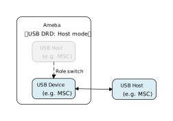
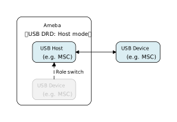
USB DRD (Dual-Role Device) is a function that allows a USB interface to dynamically switch between Host and Device roles. It breaks the limitation of fixed roles in traditional USB connections, enabling devices to flexibly change their attributes based on the connected object or application requirements.
Ameba can switch roles through software control, thereby meeting the dual system requirements for scalability and compatibility through a single physical interface.
DRD in device mode:
DRD in host mode:
Application Scenarios
DRD enhances device flexibility. Ameba can adjust its working mode to adapt to diverse interaction and expansion needs through a single physical interface. For example,
Smart Dashcam/Action Camera: In Host mode, Ameba actively writes GPS modules tracks to external USB drive; when connected to a PC, it switches to Device mode (MSC) to act as storage for direct file export.
Industrial Handheld Terminal: In Host mode, Ameba connects to barcode scanners or industrial sensors (HID/CDC) to collect field data; when connected to a management PC, it switches to Device mode (CDC/MSC) to batch upload collected logs and reports.
In-vehicle CarPlay interconnection terminal: When Ameba is powered on, it is in device mode and completes the necessary initial verification process. After passing the verification, it switches to host mode, actively connects to the in-vehicle device, and establishes dual-protocol communication with NCM and IAP2 to achieve full CarPlay functionality.
Protocol Introduction
In USB applications, the following two methods are commonly used to switch between host and device roles:
Hardware switching based on USB OTG (On-The-Go) protocol
The role is determined by relying on the state of the ID pin of the physical cable. This mechanism includes the following specific protocols:
SRP (Session Request Protocol): Allows a device to request the host to turn on VBUS power.
HNP (Host Negotiation Protocol): Allows both connection parties to temporarily exchange Host/Device roles through negotiation.
Software-Controlled DRD Switching
It does not rely on the physical connection status, but instead modifies the controller register directly through software to change roles. Although this method does not adhere to the standard USB transmission protocol, it has extremely high practical value.
Core advantages of DRD software switching compared to OTG
Despite the basic usability of hardware automatic detection, when building complex and highly reliable systems, DRD software switching demonstrates irreplaceable advantages:
Get rid of hardware dependence and adapt to Type-C
It does not rely on the ID pin, thus avoiding failures caused by hardware design defects or physical damage.
Especially in the Type-C specification, the HNP protocol defined by OTG has been deprecated, and there is no traditional ID pin. Software switching has become a solution that is more in line with modern interface specifications.
Flexible software switching
Support dynamic role changes without replacing physical cables, Users can choose to initiate the switch actively, or trigger it through various means such as external buttons, events, or message requests.
It has significantly improved the system’s fault tolerance, maintainability, and automated testing efficiency.
Class Driver
The software control of role switching for USB DRD essentially belongs to the application layer functionality, primarily involving changes in the controller’s working mode, and does not inherently require a specific “DRD class driver”. Its essence is to dynamically load the corresponding standard class driver based on the current USB role. Regarding the class drivers used by DRD in different roles, please refer to the class driver chapter corresponding to the specific device/host solution.
Application Example
Application Design
This section introduces the design of the USB DRD application example, which builds several USB examples into one image and switches between them at runtime, in any direction: device <-> host, host <-> host and device <-> device. Only one application owns the USB controller at a time.
The role switching is done at the application layer, without a dedicated DRD class driver. Switching from one application to another can be summarized as follows:
Stop the running application: tear down its class driver and the USB device or host core, and release every resource it owns
Wait for a while so that the peer sees the disconnect
Start the next application: bring up the USB device or host core and its class driver
App Manager
Each built-in application is described by a usb_app_t entry in the app table of the example, which gives its name, role and start/stop entries:
typedef struct {
    const char *name;                       /* Example directory name, e.g. "usbd_cdc_acm" */
    int (*start)(void);                     /* Bring the app up, task context only */
    int (*stop)(void);                      /* Tear it down completely, task context only, idempotent */
    u8 role;                                /* USB_APP_ROLE_DEVICE or USB_APP_ROLE_HOST */
} usb_app_t;
The start/stop entries are the example_<app>_start()/example_<app>_stop() functions exported by each standalone example, e.g. example_usbd_msc_start() and example_usbd_msc_stop(). They are the same code paths as the standalone examples, so each application behaves as its own example once started.
The app manager runs in its own thread and serializes every start, stop and switch request received from the AT+USBAPP command. Each application has its own AT command, named AT+USB<D|H><APP> after it, which is only accepted while that application runs.
Note
The SDK example switches the roles with AT commands mainly for ease of testing. In an actual product, the application can trigger the role switching in any way that suits its design, e.g. driven by a USB control message, a Wi-Fi command, or a GPIO event.
Application Start and Stop
A start brings up the USB stack in the same way as the standalone example. Taking usbd_msc and usbh_msc as examples:
MSC device start: define the configuration structure and callback functions, then initialize the underlying storage, the USB device core and the MSC class driver.
static usbd_config_t usbd_msc_cfg = {
    .speed = CONFIG_USBD_MSC_SPEED,
    .isr_priority = INT_PRI_MIDDLE,
};

static usbd_msc_cb_t usbd_msc_cb = {
    .status_changed = usbd_msc_cb_status_changed  /* USB status change callback. */
};

int ret = 0;
ret = usbd_msc_disk_init();    /* Initializes the underlying storage disk. */
if (ret != RTK_SUCCESS) {
    return;
}

ret = usbd_init(&usbd_msc_cfg);     /* Initialize USB device core driver with configuration. */
if (ret != RTK_SUCCESS) {
    usbd_msc_disk_deinit();
    return;
}

ret = usbd_msc_init(&usbd_msc_cb);  /* Initializes the MSC device class. */
if (ret != RTK_SUCCESS) {
    usbd_msc_disk_deinit();
    usbd_deinit();
    return;
}
MSC host start: define the configuration structure and callback functions, then initialize the USB host core and the MSC class driver.
static usbh_config_t usbh_cfg = {
  .speed = USB_SPEED_HIGH,
  .ext_intr_enable = USBH_SOF_INTR,
  .isr_priority = INT_PRI_MIDDLE,
  .main_task_priority = 3U,
  .tick_source = USBH_SOF_TICK,
  }

static usbh_msc_cb_t usbh_msc_usr_cb = {
  .attach = usbh_msc_cb_attach,                  /* USB device attach callback */
  .setup = usbh_msc_cb_setup,                    /* USB device setup done, indicate that device is ready for bulk transfer */
};

static const usbh_msc_config_t usbh_msc_cfg = {
  .buf_size = 0,                                 /* READ(10)/WRITE(10) bounce buffer size, 0 takes USBH_MSC_DEFAULT_BUF_SIZE */
};

static usbh_user_cb_t usbh_usr_cb = {
  .process = usbh_msc_cb_process
};

int ret = 0;
ret = usbh_init(&usbh_cfg, &usbh_usr_cb);   /* Initialize USB host core driver with configuration and user callback. */
if (ret != RTK_SUCCESS) {
    return;
}

ret = usbh_msc_init(&usbh_msc_usr_cb, &usbh_msc_cfg);  /* Initializes the MSC host class with MSC class user callback and configuration. */
if (ret != RTK_SUCCESS) {
    usbd_msc_disk_deinit();
    return;
}
A stop releases the resources in the reverse order of the start, and shall leave nothing behind, so that the free heap stays stable across repeated switches:
MSC device stop:
/* De-initializes the underlying storage disk. */
usbd_msc_disk_deinit();
/* Deinitialize MSC device class driver. */
usbd_msc_deinit();
/* Deinitialize USB device core driver. */
usbd_deinit();
MSC host stop:
/* Deinitialize MSC host class driver. */
usbh_msc_deinit();
/* Deinitialize USB host core driver. */
usbh_deinit();
The lifecycle of the worker threads of an application is tracked by usb_app_ctx_t in usb_app.h: a stop asks the workers to leave, waits up to USB_APP_JOIN_TIMEOUT_MS for each of them, and only then frees what they may touch. If a worker does not leave in time, the application keeps its resources and the manager refuses to start any further application until the board is reset.
Note
For MSC device, refer to Mass Storage Device Solution .
For MSC host, refer to Mass Storage Host Solution .
Operation method
This section introduces a USB DRD (Dual Role Device) application example that builds several USB examples into one image and switches between them at runtime with the AT+USBAPP command. Only one app owns the USB controller at a time.
The apps built in are the examples whose class is enabled in prj.conf of the example. By default only usbd_msc and usbh_msc are enabled; the other available apps are listed in prj.conf commented out, uncomment a group to add its app. Refer to {SDK}/example/usb/usb_drd/README.md for the current list of apps and their peers.
Each app behaves as its own example; refer to the corresponding device or host solution for its test procedure and expected log. Each app has its own AT command, named AT+USB<D|H><APP> after it, so no two apps share a command. It is accepted only while that app runs; otherwise it prints Not running and ends with ERROR.
Note
At most one network app (CDC ECM/NCM device or host, 4G dongle, Wi-Fi bridge, etc.) can be built into an image, otherwise the build stops with an error.
Classes with exclusive Kconfig choices take only one value per image: the device HID type, the UAC version and the MSC storage media are the ones selected in
prj.conf.
The example code is located at: {SDK}/example/usb/usb_drd. It provides a complete design reference for developers creating custom USB DRD products.
Configuration and Compilation
Compilation and Flashing
Execute the following commands in the SDK root directory to configure the environment, select the target SoC, compile the project, and flash the generated
Imagefile to the development board:# Initialize environment (required for every new terminal) source env.sh or env.bat(Windows system) # Select Target SoC (replace xxx with your specific SoCs) ameba.py soc xxx ameba.py build -a usb_drd -p
Menuconfig configuration
prj.confof this example selectsUSB Mode (DRD)and groups the options of each app, with comments; it is applied automatically when building this example. Uncomment a group to add its app, comment it out to leave the app out. The default configuration is as below:- Choose `CONFIG USB --->`: [*] Enable USB USB Mode (DRD) ---> () Auto-start USB app *** USB Device Class *** [*] MSC Select storage media (SD Card (SD mode)) ---> *** USB Host Class *** [*] MSCCONFIG_USB_APP_DEFAULT(CONFIG USB>Auto-start USB app) names an app started at boot, e.g."usbd_cdc_acm"; leave it empty to start none and wait forAT+USBAPP=start.Hardware configuration
Host apps need VBUS on the host port. Some Ameba boards require hardware rework to support USB host mode, refer to the EVB user guide for details.
Verification
This section demonstrates the verification process with the default usbd_msc and usbh_msc apps, using an SD card as the storage medium of the MSC device.
Device Startup
Insert the SD card into the development board’s card slot, reset the board, and observe the serial logs. The apps built in are listed:
[DRD-I] USB DRD demo start
[APP-I] Apps (2):
  usbd_msc device
  usbh_msc host
Commands
The apps are managed with the following AT commands on the LOGUART console. Every command ends with
OKorERROR: <code>.Command
Description
AT+USBAPP=listList the apps built in,
*marks the running one.AT+USBAPP=start,<app>Start an app; the controller must be free.
AT+USBAPP=stopStop the running app and release everything it owns.
AT+USBAPP=switch,<app>[,<ms>]Stop the running app, wait
ms(0~10000, default 500) so the peer sees the disconnect, then startapp.AT+USBAPP=statusPrint the running app, the switch count and the free heap.
AT+USBAPP=helpPrint the usage.
MSC Device Mode Test
Execute
AT+USBAPP=start,usbd_mscand connect the development board to a PC using a USB cable:[MSC-I] USBD MSC demo start [MSC-I] Disk init [USBD-A] INIT [MSC-I] Init [APP-I] Start usbd_msc (device), heap 0x... [MSC-I] ATTACHED
A new removable disk drive should automatically appear in the PC’s file manager, perform file read/write operations to verify data transmission.
Role Switching
Execute
AT+USBAPP=switch,usbh_mscto stop the MSC device and start the MSC host. Start and stop print the free heap, which shall stay stable across repeated switches:[MSC-I] USBD MSC demo stop [APP-I] Stop usbd_msc, heap 0x...->0x... [MSC-I] USBH MSC demo start [MSC-I] Wait for device attach... [APP-I] Start usbh_msc (host), heap 0x...
MSC Host Mode Test
Disconnect the development board’s USB port from the PC, and connect a USB flash drive formatted as FATFS to the board. The board identifies the MSC device and performs read/write performance tests:
[USBH-A] Dev attach, speed 0
[USBH-A] PID 6545
[USBH-A] VID 0930
[USBH-A] Addr 1
[USBH-A] MFG: TOSHIBA
[USBH-A] PROD: TransMemory
[USBH-A] SN: C03FD5F7715FE3417000DE76
[USBH-A] Enum done, 1 cfg
[USBH-A] Switch to itf: 0
[USBH-A] Class: 0x08
[USBH-A] SubClass: 0x06
[USBH-A] Protocol: 0x50
[MSC-I] ATTACH
[MSC-I] Max lun 1
[MSC-I] Lun 0
[MSC-I] SETUP
[MSC-I] Device ready
[MSC-I] FatFS USB W/R performance test start, free heap: 0x...
[MSC-I] Open file: 0:/TEST0.DAT
[MSC-I] W test: size 512, round 20...
[MSC-I] W rate 204.0 KB/s for 20 round @ 49 ms
[MSC-I] R test: size = 512 round = 20...
[MSC-I] R rate 476.1 KB/s for 20 round @ 21 ms
...
[MSC-I] File 0:/TEST0.DAT done
...
[MSC-I] FatFS USB W/R performance test done, free heap: 0x...
Note
If a stop, or the rollback of a failed start, times out (an app thread does not leave in time), the app keeps its resources, AT+USBAPP=status reports broken and no further app can be started until the board is reset.