Composite Device Solution
Overview
The USB Composite Device specification defines the device architecture and enumeration standards for carrying multiple independent function classes (such as Audio, HID, Storage, Serial, etc.) through a single physical USB interface.
Based on the USB specification officially released by the USB-IF, Ameba implements a flexible composite device functional framework. It supports aggregating multiple functional interfaces via Interface Descriptors or Interface Association Descriptors (IAD), providing capabilities for parallel enumeration, independent driver loading, and collaborative operation of multiple logical devices on the host side.

Features
Supports the following function combinations:
CDC ACM + HID
CDC ACM + MSC
CDC ACM + UAC
HID + UAC
Supports USB hot-plug
Supports fully customizable descriptors
Supports configuration of parameters such as transfer buffer size and speed mode
Application Scenarios
As a USB composite device, Ameba can simultaneously enumerate multiple device classes through a single USB physical interface, enabling parallel processing of data transmission and control interaction. It is suitable for a wide range of complex application scenarios. For example,
USB Audio Device with Remote Control (UAC + HID): Ameba provides USB audio input/output functionality (UAC) while utilizing the HID interface for media control. Users can enjoy a high-quality audio streaming experience (such as listening to music through headphones or recording with a microphone), and also interact with features like volume adjustment, muting, song switching, or RGB lighting effects control through the HID channel.
Smart Industry and 3D Printing Control (MSC + CDC ACM): Ameba combines the MSC high-capacity storage and CDC virtual serial port functions. In 3D printer or data logger scenarios, the MSC interface can be simulated as a USB flash drive for storing G-code slicing files or sensor historical data, while the CDC interface simultaneously serves as a console for the host computer to send AT commands in real time, monitor temperature, or calibrate parameters.
Automated Testing and Assistive Input (HID Mouse + CDC ACM): Ameba combines the HID mouse and CDC serial port functions. In this scenario, the CDC interface is responsible for receiving raw data (such as coordinate instructions, head tracking data) from backend scripts or sensors, while the HID interface simulates cursor movement and click actions based on these instructions. It is widely used in hardware automated testing tools or assistive input devices for the disabled.
Protocol Introduction
The USB Composite Device specification defines a device architecture capable of supporting multiple independent function interfaces via a single physical interface within the USB framework.
This mechanism enables the host to identify and enumerate a single physical device as a collection of logical functions, facilitating parallel processing and independent control across different device classes (e.g., HID, MSC, CDC).
Common implementations include wireless keyboard/mouse receivers, USB headsets with integrated audio cards, and industrial devices combining storage and debugging capabilities.
Descriptor Structure
While adhering to standard USB descriptors (Device and Configuration Descriptors), composite devices define multi-functionality by aggregating multiple Interface Descriptors within the Configuration Descriptor set.
Single-Interface Function Class
When a single interface represents a standalone function, the composite device simply aggregates these functional classes. Typical examples of single-interface function classes include HID and MSC.
Taking a HID Keyboard + HID Mouse composite device as an example, the descriptor topology is illustrated below:
Device Descriptor
|  bDeviceClass: 0xEF (Miscellaneous)
|  bDeviceSubClass: 0x02 (Common Class)
|  bDeviceProtocol: 0x01 (Interface Association Descriptor)
│
└── Configuration Descriptor
   |   bNumInterfaces: 2  (2 Interfaces)
   │   ...
   ├── Interface Descriptor 0 (HID Keyboard)
   │   bInterfaceNumber: 0
   │   bInterfaceClass: 0x03 (HID)
   │   bInterfaceSubClass: 0x01 (Boot Interface)
   │   bInterfaceProtocol: 0x01 (Keyboard)
   │
   └── Interface Descriptor 1 (HID Mouse)
       bInterfaceNumber: 1
       bInterfaceClass: 0x03 (HID)
       bInterfaceSubClass: 0x01 (Boot Interface)
       bInterfaceProtocol: 0x02 (Mouse)
HID Keyboard + HID Mouse composite device compared to individual keyboard/mouse devices, with descriptor characteristics as follows:
Descriptor Level |
Single Function Device |
Composite Device |
|---|---|---|
Device Descriptor |
|
|
Configuration Descriptor |
1 Configuration |
1 Configuration |
Interface Descriptor |
1 Interface |
2 (or more) Interfaces |
Endpoint Descriptor |
Belong to the single interface |
Each interface has independent endpoints |
Note
bDeviceClass = 0xEF: This is a standard flag for composite devices, which triggers the host driver to parse the IAD (optional) and multiple interface descriptors in the configuration descriptor,
decompose different device functions, and create these logical sub-devices. Then load the keyboard driver for Interface 0 and the mouse driver for Interface 1.
Multi-Interface Function Class
If a logical function requires the use of multiple interfaces to complete, the Interface Association Descriptor (IAD) must be included when using this type of function to associate these interfaces.
Typical multi-interface functional class
CDC (Communication Device Class): Typically requires 1 Control Interface (CCI) + 1 Data Interface (DCI).
UVC (USB Video Class): Requires 1 Video Control Interface (VC) + 1 or more Video Streaming Interfaces (VS).
UAC (USB Audio Class): Requires 1 Audio Control Interface (AC) + 1 or more Audio Stream Interfaces (AS).
Interface Association Descriptor (IAD)
IAD declares to the host that a set of consecutive interfaces that follow closely belong to the same function and should be loaded and managed by the same driver. Without IAD, the host sometimes recognizes them as two separate devices, or the driver fails to load.
Interface Association Descriptor (IAD)
├── bLength                 : 1 byte  → 0x08 (Fixed Length)
├── bDescriptorType         : 1 byte  → 0x0B (IAD type code)
├── bFirstInterface         : 1 byte  → First Interface Number
├── bInterfaceCount         : 1 bytes → Count of associated interfaces
├── bFunctionClass          : 1 byte  → Function Class Code
├── bFunctionSubClass       : 1 byte  → Function SubClass Code
├── bFunctionProtocol       : 1 byte  → Function Protocol Code
└── iFunction               : 1 byte  → Function String Descriptor Index
IAD Usage Example

Function 1: Class utilize two interfaces. In order for the host to recognize them as a single logical function, it is necessary to use IAD to associate these two interfaces.
Function 2: Class utilize a separate interface, eliminating the need for IAD association.
Class-specific request
The USB protocol specification does not define a specific “composite class request”. Their core logic lies in precisely directing Class-Specific Requests to the designated interface through the addressing mechanism in USB standard requests.
In the bmRequestType field of the SETUP packet, the lower 5 bits (Bits 0..4) represent the Recipient.
General single-function device: Control requests are typically sent to the “entire device”, meaning the Recipient is set to
Device (00000).Composite device: A large number of control requests must be precisely sent to a “specific interface”, which means setting the Recipient to
Interface (00001).
The following are the most notable key points regarding the handling of control requests by composite devices:
Field |
Value |
Meaning |
Implementation in Composite Devices |
|---|---|---|---|
bmRequestType |
0x21 / 0xA1 |
Class Request, Recipient=Interface |
Most common scenario. Examples include setting CDC baud rates or controlling HID keyboard LEDs. |
wIndex |
Interface Number |
Interface Number |
When the Recipient is Interface, wIndex must specify the target interface index (e.g., 0, 1, 2). The driver routes the request to the corresponding function driver based on this value. |
Class Driver
This section provides a detailed analysis of how to design and implement a USB composite device class driver. The composite class driver acts as a “parent class,” responsible for managing resource scheduling, request dispatching, and data processing for multiple “child classes” (such as CDC ACM, HID, MSC, etc.).
Descriptor Structure
To allow the host to correctly identify the composite device and the multiple functions it contains, the driver must dynamically assemble a complete and precise set of descriptors at runtime. The following points must be noted when generating device descriptors:
Device Descriptor
bDeviceClass: Usually set to 0xEF (Miscellaneous) or 0x00 (defined by the interface).Configuration Descriptor
This is a dynamically generated “aggregate” that contains the descriptors for all sub-functions.
bNumInterfaces: Must be the sum of the number of interfaces for all sub-functions. For example, for a composite device consisting of a CDC function (occupying 2 interfaces) and an MSC function (occupying 1 interface), this value should be 3.wTotalLength: Must be the sum of the lengths of all descriptors (Configuration, IAD, Interface, Endpoint). This value needs to be calculated precisely at runtime.Interface Association Descriptor (IAD): If a sub-function contains multiple interfaces (e.g., CDC ACM), an IAD must be used to “bundle” these interfaces together, declaring that they belong to the same function.
Endpoint Descriptor
The configuration of endpoints must be tailored to the hardware capabilities of the chip. Please refer to Hardware Configuration for details.
Endpoint selection: Available endpoints must be selected based on functional requirements (IN/OUT) and hardware support.
Maximum Packet Size (MPS): Hardware limitations need to be considered. Especially when using a dedicated transmit buffer, it is important to ensure that the size of the transmit buffer area of the IN endpoint can accommodate at least one maximum packet.
CDC ACM + MSC Example
The following section illustrates the descriptor topology of the CDC ACM + MSC composite device. These structures correspond to the standard descriptor definitions in the USB protocol specifications.
CDC ACM (Virtual Serial Port): Occupies two interfaces. To ensure the host recognizes them as a single logical function, an IAD (Interface Association Descriptor) must be used to associate these two interfaces.
MSC (Mass Storage): Operates as an independent interface and does not require IAD association.
The composite device (CDC ACM + MSC) solution utilizes 5 non-zero endpoints (excluding the default control endpoint EP0).
Interface number |
Interface Class |
Endpoints |
Description |
|---|---|---|---|
Interface 0 |
CDC Control (ACM) |
1x Interrupt IN |
Used to notify Serial State and management commands. |
Interface 1 |
CDC Data |
1x Bulk OUT, 1x Bulk IN |
Responsible for sending (OUT) and receiving (IN) virtual serial port data. |
Interface 2 |
MSC (Mass Storage) |
1x Bulk OUT, 1x Bulk IN |
Responsible for data read/write of the mass storage device (SCSI commands/data). |
In the class driver, various descriptors are generally defined as arrays. When obtaining configuration descriptors, the callback function get_descriptor of each sub-function class driver is called sequentially to aggregate them together.
 /* USB Standard Device Descriptor */
 static const u8 usbd_composite_dev_desc[USB_LEN_DEV_DESC] = {
    //...
    0xEF,       /* bDeviceClass: Miscellaneous */
    0x02,       /* bDeviceSubClass: Common Class */
    0x01,       /* bDeviceProtocol: Interface Association Descriptor */
    //...
 };

 /* USB Standard Configuration Descriptor */
 static const u8 usbd_composite_config_desc[USB_LEN_CFG_DESC] = {
    //...
    0x00, 0x00,  /* wTotalLength: calculated at runtime */
    0x03,        /* bNumInterfaces */
    //...
 };

/**
 * @brief  Get descriptor callback
 * @param  dev: USB device instance
 * @param  req: Setup request handle
 * @param  buf: Poniter to Buffer
 * @return Descriptor length
 */
 static u16 usbd_composite_get_descriptor(usb_dev_t *dev, usb_setup_req_t *req, u8 *buf)
 {
    usbd_composite_dev_t *cdev = &usbd_composite_dev;
    usb_speed_type_t speed = dev->dev_speed;
    u16 len = 0;
    u16 desc_len;
    u16 total_len = 0;

    switch (USB_HIGH_BYTE(req->wValue)) {
    //...
    case USB_DESC_TYPE_CONFIGURATION:
    case USB_DESC_TYPE_OTHER_SPEED_CONFIGURATION:
       usb_os_memcpy((void *)buf, (void *)usbd_composite_config_desc, USB_LEN_CFG_DESC);
       buf += USB_LEN_CFG_DESC;
       total_len += USB_LEN_CFG_DESC;
       desc_len = cdev->cdc->get_descriptor(dev, req, buf);
       buf += desc_len;
       total_len += desc_len;
       desc_len = cdev->msc->get_descriptor(dev, req, buf);
       total_len += desc_len;
       buf = dev->ep0_in.xfer_buf;
       if (USB_HIGH_BYTE(req->wValue) == USB_DESC_TYPE_OTHER_SPEED_CONFIGURATION) {
          buf[USB_CFG_DESC_OFFSET_TYPE] = USB_DESC_TYPE_OTHER_SPEED_CONFIGURATION;
       }
       buf[USB_CFG_DESC_OFFSET_TOTAL_LEN] = USB_LOW_BYTE(total_len);
       buf[USB_CFG_DESC_OFFSET_TOTAL_LEN + 1] = USB_HIGH_BYTE(total_len);
       len = total_len;
       break;
       }

    return len;
 }
The complete topology structure of the device descriptor is as follows:
Device Descriptor
|  bDeviceClass: 0xEF (Miscellaneous)
|  bDeviceSubClass: 0x02 (Common Class)
|  bDeviceProtocol: 0x01 (Interface Association Descriptor)
|
└── Configuration descriptor
    |   bNumInterfaces: 3 (3 Interfaces)
    |
    |   /* Function 1: CDC ACM */
    |
    ├── Interface Association Descriptor (IAD)
    |    bFirstInterface: 0
    |    bInterfaceCount: 2 (Associate Interface 0 with Interface 1)
    |    bFunctionClass:  0x02 (CDC Control)
    |    bFunctionSubClass: 0x02 (ACM)
    |
    ├── Interface Descriptor 0 (CDC Control Interface)
    |   |  bInterfaceNumber: 0
    |   |  bInterfaceClass:  0x02 (CDC Control)
    |   |  bInterfaceSubClass: 0x02 (ACM)
    |   |  ...
    |   ├── CDC Class Specific Descriptors (Header, Call Mgmt, ACM...)
    |   └── Endpoint Descriptor (Interrupt IN)
    |
    ├── Interface Descriptor 1 (CDC Data Interface)
    |   |  bInterfaceNumber: 1
    |   |  bInterfaceClass:  0x0A (CDC Data)
    |   |  ...
    |   ├── Endpoint Descriptor (Bulk OUT)
    |   └── Endpoint Descriptor (Bulk IN)
    |
    |   /* Function 2: MSC */
    |
    └── Interface Descriptor 2 (MSC Interface)
        |  bInterfaceNumber: 2
        |  bInterfaceClass:  0x08 (Mass Storage)
        |  bInterfaceSubClass: 0x06 (SCSI Transparent Command Set)
        |  bInterfaceProtocol: 0x50 (Bulk-Only Transport / BBB)
        |   ...
        ├── Endpoint Descriptor (Bulk OUT)
        └── Endpoint Descriptor (Bulk IN)
Note
For the detailed structure of CDC ACM descriptors, please refer to: CDC ACM Protocol Introduction
For the detailed structure of MSC descriptors, please refer to: MSC Protocol Introduction
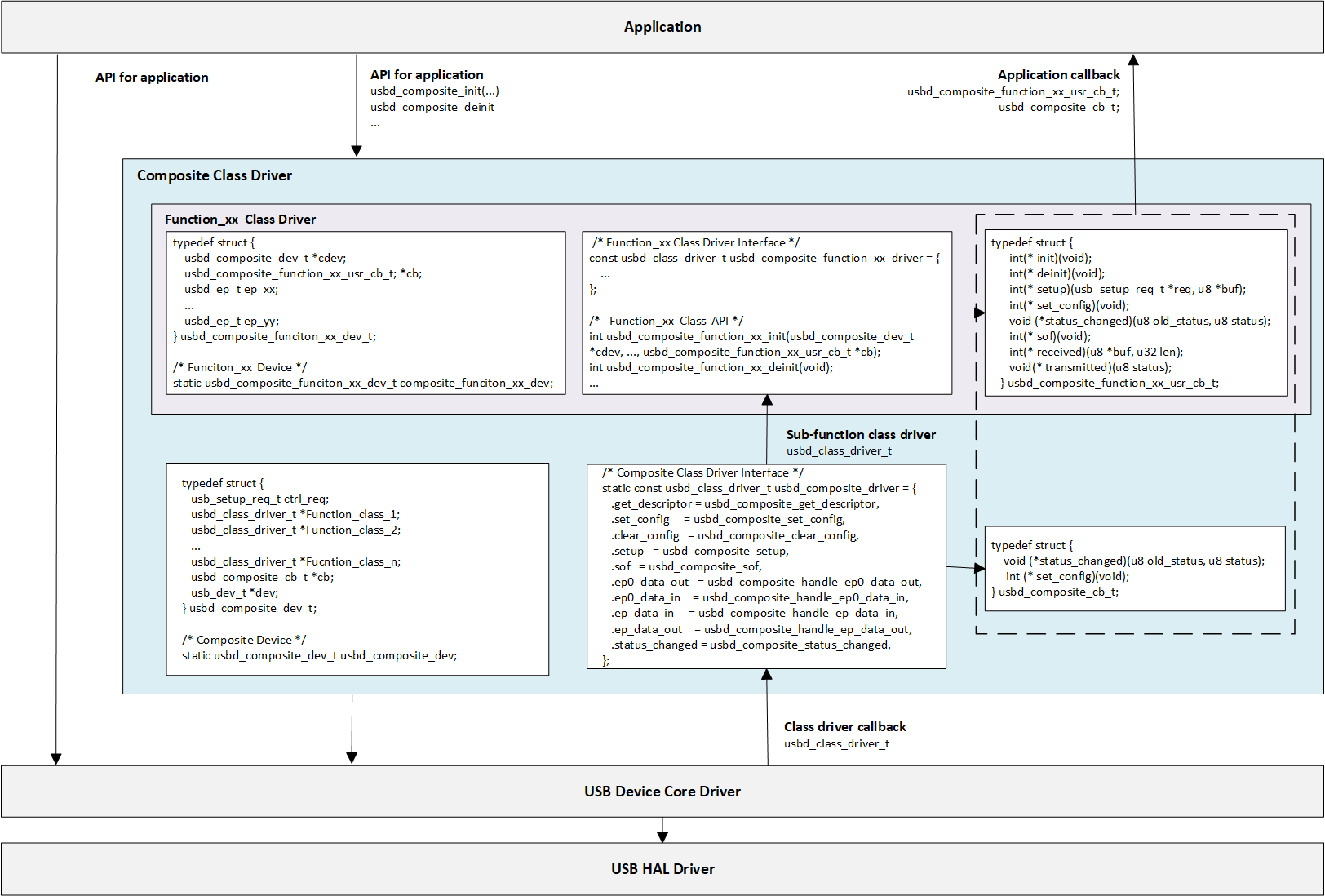
Composite Class Driver Implementation
It mainly involves defining composite devices and implementing class-driven callback functions.
Sub-function Class Driver
Each sub-function (such as CDC, MSC, HID) is an independent class driver, please refer to the corresponding chapters of the sub-function solution for details.
Independent driver structure: Each sub-driver defines a standard
usbd_class_driver_tstructure to implement its own process logic.Independent resource management: Each sub-driver is responsible for managing its own endpoints, data buffers, and data transmission and reception processing.
Composite Class Driver
The composite Class driver needs to define a standard
usbd_class_driver_tstructure. This structure serves as the unified entry point registered to the USB Core. The composite device driver is responsible for dispatching events to, or iterating through, the callback functions of the sub-function class drivers.The composite Class driver defines a standard
usbd_composite_dev_tstructure. This is the core of the composite device instance, used to manage all sub-funcion class drivers.
/* Composite Device */
static usbd_composite_dev_t usbd_composite_dev;

/* Composite Class Driver Interface */
static const usbd_class_driver_t usbd_composite_driver = {
    .get_descriptor = usbd_composite_get_descriptor,    /* Iterate through all sub-function classes to obtain the aggregated configuration descriptor */
    .set_config = usbd_composite_set_config,            /* Iterate to initialize all sub-function class endpoints and resources */
    .clear_config = usbd_composite_clear_config,        /* Iterate to release all sub-function class endpoints and resources */
    .setup = usbd_composite_setup,                      /* Dispatch class control requests to different interfaces: wIndex = Interface xx */
    .sof = usbd_composite_sof,                          /* Called during SOF interrupt, used for processing logic with strict timing requirements */
    .ep0_data_out = usbd_composite_handle_ep0_data_out, /* After the device is ready, dispatch and handle sub-function class requests for control OUT endpoints */
    .ep0_data_in = usbd_composite_handle_ep0_data_in,   /* After the device is ready, dispatch and handle sub-function class request results for control IN endpoints */
    .ep_data_in = usbd_composite_handle_ep_data_in,     /* Dispatch IN endpoint data processing; use ep_addr to determine which sub-function class the data belongs to */
    .ep_data_out = usbd_composite_handle_ep_data_out,   /* Dispatch OUT endpoint data processing; use ep_addr to determine which sub-function class the data belongs to */
    .status_changed = usbd_composite_status_changed,    /* Monitor connection status and notify the application layer or all sub-function class state machines when necessary */
};
CDC ACM + MSC Example
The following section uses CDC ACM + MSC as an example to detail the implementation of the composite device class driver.
/* Composite Device structure. */
typedef struct {
   usb_setup_req_t ctrl_req;  /* Control setup request */
   usbd_class_driver_t *cdc;  /* CDC ACM class */
   usbd_class_driver_t *msc;  /* MSC class */
   usbd_composite_cb_t *cb;   /* Composite user callback */
   usb_dev_t *dev;            /* USB device instance */
} usbd_composite_dev_t;
/* Composite Device */
static usbd_composite_dev_t usbd_composite_dev;

/* Composite Class Driver */
static const usbd_class_driver_t usbd_composite_driver = {
   .get_descriptor = usbd_composite_get_descriptor,
   .set_config = usbd_composite_set_config,
   .clear_config = usbd_composite_clear_config,
   .setup = usbd_composite_setup,
   .ep0_data_out = usbd_composite_handle_ep0_data_out,
   .ep_data_in = usbd_composite_handle_ep_data_in,
   .ep_data_out = usbd_composite_handle_ep_data_out,
   .status_changed = usbd_composite_status_changed,
};

/********************** Function 1: CDC ACM class *********************/
/* CDC ACM device structure. */
typedef struct {
   usbd_composite_dev_t *cdev;           /**< Pointer to the parent composite device structure. */
   usbd_composite_cdc_acm_usr_cb_t *cb;  /**< Pointer to the user-registered callback structure. */
   usbd_ep_t ep_bulk_in;                 /**< Bulk IN endpoint handler. */
   usbd_ep_t ep_bulk_out;                /**< Bulk OUT endpoint handler. */
#if CONFIG_COMP_CDC_ACM_NOTIFY
   usbd_ep_t ep_intr_in;                 /**< Interrupt IN endpoint handler (for notifications). */
#endif
} usbd_composite_cdc_acm_dev_t;
/* CDC ACM Device */
static usbd_composite_cdc_acm_dev_t composite_cdc_acm_dev;

/* CDC ACM Class Driver */
const usbd_class_driver_t usbd_composite_cdc_acm_driver = {
   .get_descriptor = composite_cdc_acm_get_descriptor,
   .set_config = composite_cdc_acm_set_config,
   .clear_config = composite_cdc_acm_clear_config,
   .setup = composite_cdc_acm_setup,
   .ep_data_in = composite_cdc_acm_handle_ep_data_in,
   .ep_data_out = composite_cdc_acm_handle_ep_data_out,
   .ep0_data_out = composite_cdc_acm_handle_ep0_data_out,
};

/********************** Function 2: MSC class *********************/
/* MSC device structure.  */
typedef struct {
   usbd_ep_t ep_bulk_in;                 /**< Bulk IN endpoint handler. */
   usbd_ep_t ep_bulk_out;                /**< Bulk OUT endpoint handler. */
   usbd_composite_dev_t *cdev;           /**< Pointer to the parent composite device structure. */
   //...
} usbd_composite_msc_dev_t;
/* MSC Device */
static usbd_composite_msc_dev_t usbd_composite_msc_dev;

/* MSC Class Driver */
const usbd_class_driver_t usbd_composite_msc_driver = {
   .get_descriptor = usbd_composite_msc_get_descriptor,
   .set_config = usbd_composite_msc_set_config,
   .clear_config = usbd_composite_msc_clear_config,
   .setup = usbd_composite_msc_setup,
   .ep_data_in = usbd_composite_msc_handle_ep_data_in,
   .ep_data_out = usbd_composite_msc_handle_ep_data_out,
};
The specific callbak implementation of the composite driver usbd_composite_driver:
/**
* @brief  Set composite class configuration
* @param  dev: USB device instance
* @param  config: USB configuration index
* @return Status
*/
static int usbd_composite_set_config(usb_dev_t *dev, u8 config)
{
   int ret = HAL_OK;
   usbd_composite_dev_t *cdev = &usbd_composite_dev;

   cdev->dev = dev;

   cdev->cdc->set_config(dev, config);
   cdev->msc->set_config(dev, config);

   return ret;
}

/**
* @brief  Clear composite configuration
* @param  dev: USB device instance
* @param  config: USB configuration index
* @return Status
*/
static int usbd_composite_clear_config(usb_dev_t *dev, u8 config)
{
   int ret = 0U;
   usbd_composite_dev_t *cdev = &usbd_composite_dev;

   cdev->cdc->clear_config(dev, config);
   cdev->msc->clear_config(dev, config);

   return ret;
}

/**
* @brief  Handle class specific control requests
* @param  dev: USB device instance
* @param  req: USB control requests
* @return Status
*/
static int usbd_composite_setup(usb_dev_t *dev, usb_setup_req_t *req)
{
   usbd_composite_dev_t *cdev = &usbd_composite_dev;
   usbd_ep_t *ep0_in = &dev->ep0_in;
   int ret = HAL_OK;

   switch (req->bmRequestType & USB_REQ_TYPE_MASK) {
   //...
   case USB_REQ_TYPE_CLASS:
      if ((req->wIndex == USBD_COMP_CDC_COM_ITF) || (req->wIndex == USBD_COMP_CDC_DAT_ITF)) {
         ret = cdev->cdc->setup(dev, req);
      } else if (req->wIndex == USBD_COMP_MSC_ITF) {
         ret = cdev->msc->setup(dev, req);
      } else {
         RTK_LOGS(TAG, RTK_LOG_WARN, "Invalid class req\n");
      }
      break;
   }

   return ret;
}

/**
* @brief  Data sent on non-control IN endpoint
* @param  dev: USB device instance
* @param  ep_addr: endpoint address
* @return Status
*/
static int usbd_composite_handle_ep_data_in(usb_dev_t *dev, u8 ep_addr, u8 status)
{
   int ret = HAL_OK;
   usbd_composite_dev_t *cdev = &usbd_composite_dev;

   if ((ep_addr == USBD_COMP_CDC_BULK_IN_EP) || (ep_addr == USBD_COMP_CDC_INTR_IN_EP)) {
      if (cdev->cdc->ep_data_in != NULL) {
         ret = cdev->cdc->ep_data_in(dev, ep_addr, status);
      }
   } else if (ep_addr == USBD_COMP_MSC_BULK_IN_EP) {
      if (cdev->msc->ep_data_in != NULL) {
         ret = cdev->msc->ep_data_in(dev, ep_addr, status);
      }
   }

   return ret;
}

/**
* @brief  Data received on non-control OUT endpoint
* @param  dev: USB device instance
* @param  ep_addr: endpoint address
* @return Status
*/
static int usbd_composite_handle_ep_data_out(usb_dev_t *dev, u8 ep_addr, u16 len)
{
   int ret = HAL_OK;
   usbd_composite_dev_t *cdev = &usbd_composite_dev;

   if (ep_addr == USBD_COMP_CDC_BULK_OUT_EP) {
      if (cdev->cdc->ep_data_out != NULL) {
         ret = cdev->cdc->ep_data_out(dev, ep_addr, len);
      }
   } else if (ep_addr == USBD_COMP_MSC_BULK_OUT_EP) {
      if (cdev->msc->ep_data_out != NULL) {
         ret = cdev->msc->ep_data_out(dev, ep_addr, len);
      }
   }

   return ret;
}

/**
* @brief  Handle EP0 Rx Ready event
* @param  dev: USB device instance
* @return Status
*/
static int usbd_composite_handle_ep0_data_out(usb_dev_t *dev)
{
   int ret = HAL_OK;
   usbd_composite_dev_t *cdev = &usbd_composite_dev;

   cdev->cdc->ep0_data_out(dev);

   return ret;
}

/**
* @brief  USB attach status change
* @param  dev: USB device instance
* @param  status: USB attach status
* @return void
*/
static void usbd_composite_status_changed(usb_dev_t *dev, u8 old_status, u8 status)
{
   usbd_composite_dev_t *cdev = &usbd_composite_dev;

   UNUSED(dev);

   if (cdev->cb->status_changed) {
      cdev->cb->status_changed(old_status, status);
   }
}

/**
* @brief  Get descriptor callback
* @param  dev: USB device instance
* @param  req: Setup request handle
* @param  buf: Poniter to Buffer
* @return Descriptor length
*/
static u16 usbd_composite_get_descriptor(usb_dev_t *dev, usb_setup_req_t *req, u8 *buf)
{
   usbd_composite_dev_t *cdev = &usbd_composite_dev;
   usb_speed_type_t speed = dev->dev_speed;
   u16 len = 0;
   u16 desc_len;
   u16 total_len = 0;

   switch (USB_HIGH_BYTE(req->wValue)) {
   //...
   case USB_DESC_TYPE_CONFIGURATION:
   case USB_DESC_TYPE_OTHER_SPEED_CONFIGURATION:
      usb_os_memcpy((void *)buf, (void *)usbd_composite_config_desc, USB_LEN_CFG_DESC);
      buf += USB_LEN_CFG_DESC;
      total_len += USB_LEN_CFG_DESC;
      desc_len = cdev->cdc->get_descriptor(dev, req, buf);
      buf += desc_len;
      total_len += desc_len;
      desc_len = cdev->msc->get_descriptor(dev, req, buf);
      total_len += desc_len;
      buf = dev->ep0_in.xfer_buf;
      if (USB_HIGH_BYTE(req->wValue) == USB_DESC_TYPE_OTHER_SPEED_CONFIGURATION) {
         buf[USB_CFG_DESC_OFFSET_TYPE] = USB_DESC_TYPE_OTHER_SPEED_CONFIGURATION;
      }
      buf[USB_CFG_DESC_OFFSET_TOTAL_LEN] = USB_LOW_BYTE(total_len);
      buf[USB_CFG_DESC_OFFSET_TOTAL_LEN + 1] = USB_HIGH_BYTE(total_len);
      len = total_len;
      break;
      }

   return len;
}
Application Callback API
The driver provides callback function interfaces for the application layer, allowing application code to respond to USB events and handle business logic.
Composite Application Callback API
usbd_composite_cb_tis a callback structure for the status of the entire composite device, where the application layer implements specific business logic.Function Class Application Callback API
This is the callback customized for each sub-function, This is a callback customized for each function, implemented by the application layer. Generally, the following can be implemented:
typedef struct {
   int(* init)(void);
   int(* deinit)(void);
   int(* setup)(usb_setup_req_t *req, u8 *buf);
   int(* set_config)(void);
   void (*status_changed)(u8 old_status, u8 status);
   int(* sof)(void);
   int(* received)(u8 *buf, u32 len);
   void(* transmitted)(u8 status);
} usbd_composite_function_class_xx_usr_cb_t;
API
Description
init
Called during class driver initialization; used to initialize application-specific resources.
deinit
Called during class driver de-initialization; used to release application-specific resources.
setup
Called during the setup or data stage of a control transfer; used to handle application-specific control requests.
set_config
Called within the class driver’s set_config callback; used to notify the application layer that the UAC class driver is ready.
status_changed
Called when the USB connection status changes; used by the application layer to handle USB hot-plug events.
sof
Called when an SOF interrupt is received; used by the application layer to handle clock synchronization.
transmitted
Called upon completion of an IN transfer; used by the application layer to asynchronously obtain the IN transfer status.
received
Called upon completion of an OUT transfer; used by the application layer to asynchronously obtain the OUT transfer status.
CDC ACM + MSC Example
The following section takes CDC ACM + MSC as an example to introduce the customized sub-function application layer callback (MSC does not use application layer callback).
/**
* @brief User callback structure for CDC ACM events.
* @details This structure allows the application layer to handle CDC ACM events.
*/
typedef struct {
   int(* init)(void);                             /**< Called during class driver initialization for application resource setup. */
   int(* deinit)(void);                           /**< Called during class driver deinitialization for resource cleanup. */
   int(* setup)(usb_setup_req_t *req, u8 *buf);   /**< Called during control transfer SETUP/DATA phases to handle application-specific control requests. */
   int(* received)(u8 *buf, u32 len);             /**< Called when new data is received on the Bulk OUT endpoint. */
   void(* transmitted)(u8 status);                /**< Called after data transmission on the Bulk IN endpoint is complete. */
} usbd_composite_cdc_acm_usr_cb_t;
API for Application
The application layer controls the lifecycle of the entire composite device driver through the following two main functions:
usbd_composite_init(): Initialization FunctionReceives parameters passed by the application layer, such as endpoint buffer size and callback function sets for each sub-function.
Calls the initialization function for each sub-function.
Links the sub-function driver instances to the
usbd_composite_devstructure.Finally, calls
usbd_register_class()to register the composite device driver with the USB Core, making it effective.
usbd_composite_deinit(): De-initialization FunctionCalls
usbd_unregister_class()to unregister the composite device driver from the USB Core.Sequentially calls the de-initialization function for each sub-function to release all resources.
CDC ACM + MSC Example
The following section takes CDC ACM + MSC as an example to introduce the implementation of application-layer-oriented APIs for composite device class drivers.
/**
* @brief  Init composite class
* @param  cdc_bulk_out_xfer_size: CDC ACM bulk out xfer buffer size
* @param  cdc_bulk_in_xfer_size: CDC ACM bulk in xfer buffer size
* @param  cdc_cb: CDC ACM user callback
* @param  cb: composite user callback
* @return Status
*/
int usbd_composite_init(u16 cdc_bulk_out_xfer_size, u16 cdc_bulk_in_xfer_size, usbd_composite_cdc_acm_usr_cb_t *cdc_cb, usbd_composite_cb_t *cb)
{
   int ret;
   usbd_composite_dev_t *cdev = &usbd_composite_dev;

   if (cdc_cb == NULL) {
      ret = HAL_ERR_PARA;
      RTK_LOGS(TAG, RTK_LOG_ERROR, "Invalid user cb\n");
      return ret;
   }

   if (cb != NULL) {
      cdev->cb = cb;
   }

   ret = usbd_composite_cdc_acm_init(cdev, cdc_bulk_out_xfer_size, cdc_bulk_in_xfer_size, cdc_cb);
   if (ret != HAL_OK) {
      RTK_LOGS(TAG, RTK_LOG_ERROR, "Init CDC ACM itf fail: %d\n", ret);
      return ret;
   }

   ret = usbd_composite_msc_init(cdev);
   if (ret != HAL_OK) {
      RTK_LOGS(TAG, RTK_LOG_ERROR, "Init MSC itf fail: %d\n", ret);
      usbd_composite_cdc_acm_deinit();
      return ret;
   }

   cdev->cdc = (usbd_class_driver_t *)&usbd_composite_cdc_acm_driver;
   cdev->msc = (usbd_class_driver_t *)&usbd_composite_msc_driver;

   usbd_register_class(&usbd_composite_driver);

   return ret;
}

/**
* @brief  DeInit composite class
* @param  void
* @return Status
*/
void usbd_composite_deinit(void)
{
   usbd_unregister_class();

   usbd_composite_msc_deinit();
   usbd_composite_cdc_acm_deinit();
}
Note
For detailed class driver descriptions, please refer to: Vendor-Specific Device Solution
API Reference
For detailed function prototypes and usage, please refer to the Driver API
Application Example
This section takes USB Composite (CDC ACM + MSC) as an example to introduce the complete application implementation and the method of running example application.
Application Design
This section provides a detailed introduction to the complete development and design process of composite device drivers, covering driver initialization, hotplug management, and resource release.
Driver Initialization
The initialization process involves sequentially completing USB Core initialization, and Composite class driver loading. Defining the configuration structure and registering user callback functions are essential steps.
Configuration: Configure USB speed mode and interrupt priority.
Callback Registration: Define the user callback structure:cpp:struct:usbd_composite_cb_t 和
usbd_composite_fucntion_xx_usr_cband mount handler functions for each stage.Core Initialization: Call
usbd_init()to initialize the USB core.Class Driver Init: Call
usbd_composite_init()to initialize the composite class driver.
The following section uses CDC ACM + MSC as an example to introduces the implementation of composite device driver initialization.
Most of the interactions with the MSC are automatically handled by the protocol stack, while the application layer primarily focuses on disk initialization and deinitialization. Prior to USB initialization, it is essential to ensure that the storage medium (such as an SD card or Flash) is ready and invoke the disk initialization interface.
static usbd_config_t composite_cfg = {
   .speed = CONFIG_USBD_COMPOSITE_SPEED,
   .isr_priority = CONFIG_USBD_COMPOSITE_ISR_THREAD_PRIORITY,
   .intr_use_ptx_fifo = 0U,
}

static usbd_composite_cdc_acm_usr_cb_t composite_cdc_acm_usr_cb = {
   .init = composite_cdc_acm_cb_init,
   .deinit = composite_cdc_acm_cb_deinit,
   .setup = composite_cdc_acm_cb_setup,
   .received = composite_cdc_acm_cb_received,
   .transmitted = composite_cdc_acm_cb_transmitted
};

static usbd_composite_cb_t composite_cb = {
   .status_changed = composite_cb_status_changed,
};

int ret = 0;

/* Initializes the underlying storage disk. */
ret = usbd_composite_msc_disk_init();
if (ret != HAL_OK) {
   return;
}

/* Initialize USB device core driver with configuration. */
ret = usbd_init(&composite_cfg);
if (ret != HAL_OK) {
   usbd_composite_msc_disk_deinit();
   return;
}

/* Initialize composite class driver.   */
ret = usbd_composite_init(CONFIG_USBD_COMPOSITE_CDC_ACM_MSC_BULK_OUT_XFER_SIZE,
                     CONFIG_USBD_COMPOSITE_CDC_ACM_MSC_BULK_IN_XFER_SIZE,
                     &composite_cdc_acm_usr_cb,
                     &composite_cb);
if (ret != HAL_OK) {
   usbd_composite_msc_disk_deinit();
   usbd_composite_deinit();
   return;
}
USB Hot-plug Event Handling
Monitor USB connection status changes (connected/disconnected) by registering the status_changed callback function.
Refer to Device Connection Status Detection for more details.
Note
It is recommended to use a semaphore to notify a dedicated task thread for processing, to avoid executing time-consuming operations within the interrupt context.
The following section uses CDC ACM + MSC as an example to introduces the USB Hot-plug Event Handling of composite device driver.
static u8 composite_attach_status;
static rtos_sema_t composite_attach_status_changed_sema;

/* USB status change callback */
static usbd_composite_cb_t composite_cb = {
   .status_changed = composite_cb_status_changed,
};

/* Callback executed in ISR context */
static void composite_cb_status_changed(u8 old_status, u8 status)
{
   composite_attach_status = status;
   rtos_sema_give(composite_attach_status_changed_sema);
}

/* Thread Context: Handle the state machine */
static void composite_hotplug_thread(void *param)
{
   int ret = 0;

   UNUSED(param);

   for (;;) {
         /* Wait for status change signal */
      if (rtos_sema_take(composite_attach_status_changed_sema, RTOS_SEMA_MAX_COUNT) == RTK_SUCCESS) {
         if (composite_attach_status == USBD_ATTACH_STATUS_DETACHED) {
            RTK_LOGS(TAG, RTK_LOG_INFO, "DETACHED\n");
            /* 1. Clean up composite class resources */
            usbd_composite_deinit();
            /* 2. De-initialize USB core */
            ret = usbd_deinit();
            if (ret != 0) {
               break;
            }
            usbd_composite_msc_disk_deinit();
            /* 3. Re-initialize for next connection */
            usbd_composite_msc_disk_init();
            ret = usbd_init(&composite_cfg);
            if (ret != 0) {
               break;
            }
            ret = usbd_composite_init(CONFIG_USBD_COMPOSITE_CDC_ACM_MSC_BULK_OUT_XFER_SIZE,
                              CONFIG_USBD_COMPOSITE_CDC_ACM_MSC_BULK_IN_XFER_SIZE,
                              &composite_cdc_acm_usr_cb,
                              &composite_cb);
            if (ret != 0) {
               usbd_deinit();
               break;
            }
         } else if (composite_attach_status == USBD_ATTACH_STATUS_ATTACHED) {
            RTK_LOGS(TAG, RTK_LOG_INFO, "ATTACHED\n");
         } else {
            RTK_LOGS(TAG, RTK_LOG_INFO, "INIT\n");
         }
      }
   }
   RTK_LOGS(TAG, RTK_LOG_ERROR, "Hotplug thread fail\n");
   rtos_task_delete(NULL);
}
Driver Deinitialization
When the USB function is no longer needed or the system is shut down, resources need to be released in the reverse order of initialization. The following section uses CDC ACM + MSC as an example to introduces the implementation of composite device driver deinitialization.
/* De-initializes the underlying storage disk. */
usbd_composite_msc_disk_deinit();

/* Deinitialize composite class driver first */
usbd_composite_deinit();

/* Deinitialize USB device core driver */
usbd_deinit();
Operation method
This example demonstrates how to use the composite device protocol stack to configure the Ameba development board as a device featuring both CDC ACM (Virtual Serial Port) and MSC (Mass Storage) capabilities simultaneously.
When the development board is connected to a USB Host (e.g., a PC), the system will recognize two independent logical devices. Users can communicate with the board via a serial tool and, at the same time, read from and write to the on-board SD card just like operating a standard USB flash drive.
The example code path is: {SDK}/example/usb/usbd_composite_cdc_acm_msc. It provides provides a complete reference solution for developers to design custom Composite products.
Configuration and Compilation
Compilation and Flashing
Execute the following commands in the SDK root directory to configure the environment, select the target SoC, compile the project, and flash the generated
Imagefile to the development board.# Initialize environment (required for every new terminal) source env.sh or env.bat(Windows system) # Select Target SoC (replace xxx with your specific SoCs) ameba.py soc xxx ameba.py build -a usbd_composite_cdc_acm_msc -p
Confirmation of Menuconfig configuration
If compilation fails, please execute
ameba.py menuconfigand confirm thatUSB Composite Deviceand the specific composite class combination (CDC ACM + MSC) have been selected.- Choose `CONFIG USB --->`: [*] Enable USB USB Mode (Device) ---> [*] Composite Select Composite Class (CDC ACM + MSC) ---> (X) CDC ACM + MSC Select storage media (SD Card (SD mode)) --->
Verification
Device Startup
Reset the development board and observe the serial log; it should display the following startup message:
[COMP] USBD COMP demo start
Connect to Host
Connect the development board to a PC using a USB cable.
When the device is connected to a Windows PC host, the Device Manager will present the following hierarchical structure:
Under
Universal Serial Bus Controller, there appears: USB Composite Device (driven by usbccgp.sys).Under the
Universal Serial Bus Controller, there appears: USB Mass Storage Device (corresponding to the MSC function).Under
Ports (COM and LPT), there appears: USB Serial Device (COMx) (corresponding to the CDC ACM function).
Function verification 1: CDC ACM (virtual serial port)
Open the serial port debugging tool (such as Realtek Trace Tool) on the PC.
Select the virtual serial port number enumerated by the development board.
Send any character, and the development board will echo the received data as is to verify normal communication.
Function verification 2: MSC (mass storage)
A new removable disk drive letter should automatically pop up in the PC’s file explorer. Users can double-click to open the drive letter and perform file read and write operations on the inserted SD card.
Note
This example uses an SD card as the underlying storage medium for the MSC. Please ensure that a formatted SD card is inserted into the on-board SDIOH slot of the development board. Please avoid removing the SD card or disconnecting the USB connection during data reading and writing to prevent damage to the file system.
