Video Host Solution
Overview
The USB Video Class (UVC) protocol defines the industry standard for transmitting video data over a USB interface. In Host mode, the Ameba platform can identify and drive external USB camera devices through this protocol.
The UVC host protocol stack on the Ameba platform focuses on video capture scenarios. It is based on the USB Video Class (UVC) 1.1 specification and is compatible with the UVC 1.5 specification, and abstracts external USB cameras as local video input interfaces of the system. This solution supports plug-and-play, can seamlessly interface with the system’s built-in video processing framework, and provides convenient and flexible visual perception extension capabilities for devices.

Features
The Ameba UVC host driver is designed to provide efficient and compatible video input capabilities. Its main features are as follows:
Extensive Device Compatibility: Supports UVC-compliant USB camera devices (such as USB webcams, industrial cameras, USB microscopes).
Automated Enumeration and Configuration: Automatically parses device descriptors, identifies video streaming interfaces and control interfaces, and establishes isochronous transmission pipes.
Mainstream Video Format Support:
Compressed formats: MJPEG, H.264
Uncompressed formats: UVC-compliant uncompressed YUV video formats, with the specific pixel format (e.g., YUY2) determined by the camera’s UVC descriptors.
Deep System-Level Integration: Exposes a unified API to upper-layer applications and hides low-level USB transmission details.
Hot-Plug Support: Supports plug-and-play and dynamic removal of USB peripherals without restarting the system.
Application Scenarios
As a USB host, Ameba is responsible for enumerating USB cameras, parsing video descriptors, and establishing a stable image data stream. This solution is suitable for embedded applications that require visual data acquisition while also pursuing low power consumption and rapid integration, such as:
Intelligent Monitoring and Security: Ameba captures images in real time through USB cameras, combined with network transmission or local storage, for use in home monitoring, doorbell peepholes, or industrial site surveillance.
Visual Recognition Terminals: As a front-end acquisition device for edge computing nodes, it acquires image data and passes it to subsequent AI algorithms for face recognition, QR code scanning, or object detection.
Video Calling Devices: Combined with Wi-Fi or cellular network modules, it captures user video streams through generic USB cameras to implement low-cost VoIP video intercom functions.
Protocol Introduction
The UVC (USB Video Class) protocol defines standard interfaces within the USB specification framework for implementing Control Management and Video Stream Transmission between a host and video capture devices. The host driver establishes video data channels through this protocol to achieve real-time camera preview, recording, and parameter adjustment.
Protocol Documents
USB-IF has officially released the UVC class base protocol and specifications for multiple Payload formats. Please refer to the following core documents during development:
Specification Type |
Document |
|---|---|
UVC 1.1 (Video Class Base Protocol) |
|
UVC 1.5 (Video Class Base Protocol) |
|
Payload Specs (Payload Formats) |
Contained within the USB_Video_Payload_*.pdf files in the archive above. |
Term Definition
The definitions of general UVC (USB Video Class) technical terms used in this document are as follows:
Term |
Description |
|---|---|
VC Interface (Video Control Interface) |
Video Control Interface. As the core control center of the UVC device, it manages the topology of the video device (such as the connection relationship between Units and Terminals). The host sends control requests via this interface, such as adjusting brightness, contrast, or performing Pan/Tilt/Zoom control. |
VS Interface (Video Streaming Interface) |
Video Streaming Interface. Responsible for the actual transmission of video payload data, usually using Isochronous or Bulk pipes. Each VS Interface contains specific video format information (such as YUV, MJPEG, H.264) and related frame descriptors. |
Input Terminal (IT) |
Input Terminal. The entry point where the video data stream enters the UVC function topology. Common input terminals include Camera Sensors or Composite Video Input interfaces. It represents the physical source of data. |
Output Terminal (OT) |
Output Terminal. The exit point where the video data stream leaves the UVC function topology. The most common output terminal is the USB Streaming Terminal, indicating that data will be sent to the host via the USB bus. |
Processing Unit (PU) |
Processing Unit. A processing node located after the Input Terminal, used to adjust the video image itself. It provides control capabilities over image quality, such as Brightness, Contrast, Hue, Saturation, and Sharpness. |
Extension Unit (XU) |
Extension Unit. A functional module that the UVC specification allows manufacturers to customize. Through XU, manufacturers can define specific control commands outside the standard UVC specification and access them on the host side via matching drivers or applications. |
Probe & Commit Control |
Negotiation and Commit Control. This is a critical mechanism in the process of establishing a video stream. The host first sends a “Probe” request to query the bandwidth and parameters supported by the device. After reaching an agreement, it sends a “Commit” request to lock the configuration before the video stream transmission can be started. |
Payload Header |
Payload Header. Header information in UVC video stream data packets, containing key synchronization information such as frame toggle (Frame ID), timestamp (PTS/SCR), and error flags. |
Protocol Framework
The UVC Host protocol stack adopts a layered architecture design, aiming to decouple the USB transport layer from the upper-layer video application or multimedia framework.

Component Responsibilities
Application
Located at the top layer of the architecture, responsible for specific business logic processing. Includes video preview, recording applications, or AI algorithms and network streaming services based on video streams.
Video Middleware
Acts as an abstraction layer connecting the upper and lower layers. It provides a unified data acquisition interface upwards for the application layer, shielding underlying differences; it is responsible for video stream encoding/decoding processing, format conversion, and buffer queue management.
UVC Class Driver
The core intermediate layer, implementing behaviors defined by the UVC specification:
Topology Parsing: Parses the internal topology (Unit/Terminal) of the Video Control Interface (VC) and format descriptors of the Video Streaming Interface (VS).
Stream Negotiation: Implements the Probe and Commit processes to negotiate parameters such as resolution, frame rate, and bandwidth.
Frame Reassembly and Submission: Parses the UVC Payload Header, handles frame start/end indicators (FID/EOF), reassembles scattered USB packets into complete video frames, and submits them to the middleware layer frame by frame.
USB Core & HCD (Host Controller Driver)
Underlying drivers responsible for handling USB standard enumeration, isochronous pipe management, and scheduling of underlying physical data transmission.
Communication Mechanism
Standard UVC devices aggregate the following interfaces through the Interface Association Descriptor (IAD):
Video Control Interface (VC Interface) - Topology Control
Transfer Mechanism: Based on Control Transfer over the default pipe 0 (EP0).
Core Function: Sends class-specific requests to control Unit/Terminal attributes, completing parameter negotiation via Probe and Commit processes.
Video Streaming Interface (VS Interface) - Data Pipeline
Transfer Mechanism: Uses Isochronous transfer mode to carry high-bandwidth video streams.
Features: Guarantees bandwidth and low latency (no retransmission), suitable for real-time video preview.
Descriptor Structure
In addition to standard USB descriptors (such as Device Descriptor, Configuration Descriptor, Endpoint Descriptor), UVC devices also define Class-Specific Descriptors.
These descriptors are classified into Class-Specific Video Control Interface Descriptors (VC) and Class-Specific Video Streaming Interface Descriptors (VS) based on the interface they belong to.
Descriptor Topology
Device Descriptor
└── Identifies basic device information (USB Version 2.00, Composite Device)

Configuration Descriptor
├── Contains total length, power supply (500mA), etc.
│
├── Interface Association Descriptor (IAD)
│       └── Groups Interface 0 (VC) and Interface 1 (VS) as a Video Function
│
├── Video Control (VC) Interface Descriptor (Interface 0)
│       ├── Standard Interface Descriptor (AlternateSetting 0, Video Control Class)
│       ├── Class-Specific VC Header (declares UVC version, clock frequency)
│       ├── Class-Specific Descriptor Collection (Topology)
│       │       ├── Input Terminal (Camera)
│       │       ├── Processing Unit
│       │       ├── Extension Unit (Vendor Specific Controls)
│       │       └── Output Terminal (USB Streaming)
│       └── Standard Endpoint Descriptor (Interrupt IN for Status)
│
└── Video Streaming (VS) Interface Descriptor (Interface 1)
                ├── Alternate Setting 0: Control transfer active state (negotiation only, no data endpoint)
                │ ├── Standard Interface Descriptor (Interface 1, Streaming Class)
                │ ├── Class-Specific VS Header
                │ ├── Format Descriptor
                │ │     └── Frame Descriptor (various resolutions and frame rates)
                │ ├── Format Descriptor
                │ │     └── Frame Descriptor (various resolutions and frame rates)
                │ ├── Still Image Frame Descriptor
                │ └── Color Matching Descriptor
                │
                ├── Alternate Setting 1: Data transfer active state (with data endpoint)
                │ ├── Standard Interface Descriptor (Interface 1, Streaming Class)
                │ └── Standard Endpoint Descriptor (ISO IN endpoint, e.g., Low Bandwidth)
                │
                ├── Alternate Setting 2
                │ ...... Can configure multiple different settings as needed (e.g., Medium to High Bandwidth)
                │
                └── ...... (Other Alternate Settings for different packet sizes)

Device Qualifier Descriptor
└── Device information while running in another speed mode (e.g., High Speed vs Full Speed capability)

Other Speed Configuration Descriptor
├── Configuration information while running in another speed mode
│
├── Interface Association Descriptor (IAD)
│       └── Groups Interface 0 (VC) and Interface 1 (VS) as a Video Function
│
├── Video Control (VC) Interface Descriptor (Interface 0)
│       ├── Standard Interface Descriptor (AlternateSetting 0, Video Control Class)
│       └── Class-Specific Descriptor Collection (Same Topology as main configuration)
│               ├── Input Terminal
│               ├── Processing Unit
│               ├── Extension Unit
│               └── Output Terminal
│
└── Video Streaming (VS) Interface Descriptor (Interface 1)
                ├── Alternate Setting 0: Control transfer active state (negotiation only)
                │ ├── Standard Interface Descriptor (Interface 1, Streaming Class)
                │ ├── Class-Specific VS Header
                │ ├── Format Descriptor
                │ │     └── Frame Descriptor
                │ └── Color Matching Descriptor
                │
                ├── Alternate Setting 1: Data transfer active state
                │ ├── Standard Interface Descriptor (Streaming Class)
                │ └── Standard Endpoint Descriptor (ISO IN endpoint)
                │
                └── ...... (Other alternate settings typically available in other speed modes)
UVC Video Control (VC) Interface
Video Control Interface Descriptor
Interface Header Descriptor
├── bLength            : 1 byte  → Total descriptor length (13 bytes)
├── bDescriptorType    : 1 byte  → 0x24 (CS_INTERFACE)
├── bDescriptorSubtype : 1 byte  → 0x01 (VC_HEADER)
├── bcdUVC             : 2 bytes → Video Class Specification Release Number (0x0100 = 1.00)
├── wTotalLength       : 2 bytes → Total number of bytes for all VC descriptors
├── dwClockFreq        : 4 bytes → Clock frequency in Hz (e.g., 0x02DC6C00 = 48 MHz)
├── bInCollection      : 1 byte  → Number of VideoStreaming interfaces
└── baInterfaceNr(1)   : 1 byte  → Interface number of the first VideoStreaming interface (0x01)
Input Terminal Descriptor (Camera)
Input Terminal Descriptor
├── bLength            : 1 byte  → Total descriptor length (18 bytes)
├── bDescriptorType    : 1 byte  → 0x24 (CS_INTERFACE)
├── bDescriptorSubtype : 1 byte  → 0x02 (VC_INPUT_TERMINAL)
├── bTerminalID        : 1 byte  → Unique ID of this Terminal (0x01)
├── wTerminalType      : 2 bytes → 0x0201 (ITT_CAMERA)
├── bAssocTerminal     : 1 byte  → ID of associated Output Terminal (0x00 = None)
├── iTerminal          : 1 byte  → String descriptor index
├── wObjectiveFocalMin : 2 bytes → Min focal length (0 = not supported)
├── wObjectiveFocalMax : 2 bytes → Max focal length
├── wOcularFocalLength : 2 bytes → Ocular focal length
├── bControlSize       : 1 byte  → Size of bmControls (3 bytes)
└── bmControls         : 3 bytes → Bitmap of supported controls
                                                        • D1: Auto-Exposure Mode
                                                        • D3: Exposure Time (Absolute)
                                                        • D5: Focus (Absolute)
                                                        • D9: Zoom (Absolute)
                                                        • D11: Pan (Absolute)
                                                        • D15: Tilt (Absolute)
Processing Unit Descriptor
Processing Unit Descriptor
├── bLength            : 1 byte  → Total descriptor length (11 bytes)
├── bDescriptorType    : 1 byte  → 0x24 (CS_INTERFACE)
├── bDescriptorSubtype : 1 byte  → 0x05 (VC_PROCESSING_UNIT)
├── bUnitID            : 1 byte  → Unique ID of this Unit (0x02)
├── bSourceID          : 1 byte  → ID of the source connected to this unit (0x01 = Camera IT)
├── wMaxMultiplier     : 2 bytes → Max digital zoom multiplier
├── bControlSize       : 1 byte  → Size of bmControls (2 bytes)
└── bmControls         : 2 bytes → Bitmap of supported image controls
                                                        • D0: Brightness
                                                        • D1: Contrast
                                                        • D2: Hue
                                                        • D3: Saturation
                                                        • D4: Sharpness
                                                        • D6: White Balance Temperature
Extension Unit Descriptor
Extension Unit Descriptor
├── bLength            : 1 byte  → Total descriptor length (29 bytes)
├── bDescriptorType    : 1 byte  → 0x24 (CS_INTERFACE)
├── bDescriptorSubtype : 1 byte  → 0x06 (VC_EXTENSION_UNIT)
├── bUnitID            : 1 byte  → Unique ID of this Unit (0x03)
├── guidExtensionCode  : 16 bytes→ Vendor-specific GUID (e.g., {0FB885C3-...})
├── bNumControls       : 1 byte  → Number of controls in this XU (0x05)
├── bNrInPins          : 1 byte  → Number of input pins (0x01)
├── baSourceID[1]      : 1 byte  → ID of the source connected (0x02 = PU)
├── bControlSize       : 1 byte  → Size of bmControls (4 bytes)
└── bmControls         : 4 bytes → Bitmap of supported vendor controls
Output Terminal Descriptor
Output Terminal Descriptor
├── bLength            : 1 byte  → Total descriptor length (9 bytes)
├── bDescriptorType    : 1 byte  → 0x24 (CS_INTERFACE)
├── bDescriptorSubtype : 1 byte  → 0x03 (VC_OUTPUT_TERMINAL)
├── bTerminalID        : 1 byte  → Unique ID of this terminal (0x05)
├── wTerminalType      : 2 bytes → 0x0101 (TT_STREAMING)
├── bAssocTerminal     : 1 byte  → Associated Input Terminal ID
├── bSourceID          : 1 byte  → ID of the connected Source (0x04 = XU)
└── iTerminal          : 1 byte  → String descriptor index
UVC Video Stream (VS) Interface
Video Stream Interface Descriptor
Class-Specific VS Input Header Descriptor
├── bLength            : 1 byte  → Total descriptor length (15 bytes)
├── bDescriptorType    : 1 byte  → 0x24 (CS_INTERFACE)
├── bDescriptorSubtype : 1 byte  → 0x01 (VS_INPUT_HEADER)
├── bNumFormats        : 1 byte  → Number of video formats supported (0x02)
├── wTotalLength       : 2 bytes → Total length of all VS specific descriptors
├── bEndpointAddress   : 1 byte  → Address of the ISO IN endpoint (0x81)
├── bmInfo             : 1 byte  → Capabilities (0x00)
├── bTerminalLink      : 1 byte  → ID of the Output Terminal in VC interface (0x05)
├── bStillCaptureMethod: 1 byte  → Method of still image capture (0x02)
├── bTriggerUsage      : 1 byte  → Trigger usage (0x00)
├── bControlSize       : 1 byte  → Size of control field (1 byte)
└── bmaControls(n)     : n bytes → Controls for each format
Video Stream Format Type Descriptor
Video Streaming Format Type Descriptor(MJPEG)
├── bLength            : 1 byte  → Total descriptor length (11 bytes)
├── bDescriptorType    : 1 byte  → 0x24 (CS_INTERFACE)
├── bDescriptorSubtype : 1 byte  → 0x06 (VS_FORMAT_MJPEG)
├── bFormatIndex       : 1 byte  → Index of this format (0x01)
├── bNumFrameDescriptors: 1 byte → Number of frame descriptors (0x09)
├── bmFlags            : 1 byte  → Characteristics (0x01 = Fixed Sample Size)
├── bDefaultFrameIndex : 1 byte  → Default frame index (0x01)
├── bAspectRatioX      : 1 byte  → X dimension of aspect ratio
├── bAspectRatioY      : 1 byte  → Y dimension of aspect ratio
├── bmInterlaceFlags   : 1 byte  → Interlace information (0x00 = Progressive)
└── bCopyProtect       : 1 byte  → Duplication restrictions (0x00)
Video Streaming Format Type Descriptor(Uncompressed)
├── bLength            : 1 byte  → Total descriptor length (27 bytes)
├── bDescriptorType    : 1 byte  → 0x24 (CS_INTERFACE)
├── bDescriptorSubtype : 1 byte  → 0x04 (VS_FORMAT_UNCOMPRESSED)
├── bFormatIndex       : 1 byte  → Index of this format (0x02)
├── bNumFrameDescriptors: 1 byte → Number of frame descriptors
├── guidFormat         : 16 bytes→ GUID identifying the format (YUY2: {32595559-...})
└── bBitsPerPixel      : 1 byte  → Bits per pixel (0x10 = 16 bits)
Video Stream Frame Type Descriptor
Video Streaming Frame Type Descriptor (MJPEG)
├── bLength            : 1 byte  → Total descriptor length (e.g., 34 bytes)
├── bDescriptorType    : 1 byte  → 0x24 (CS_INTERFACE)
├── bDescriptorSubtype : 1 byte  → 0x07 (VS_FRAME_MJPEG)
├── bFrameIndex        : 1 byte  → Index of this frame (0x01)
├── bmCapabilities     : 1 byte  → Still image support, etc.
├── wWidth             : 2 bytes → Frame Width (e.g., 0x0A20 = 2592)
├── wHeight            : 2 bytes → Frame Height (e.g., 0x0798 = 1944)
├── dwMinBitRate       : 4 bytes → Min Bit Rate (bps)
├── dwMaxBitRate       : 4 bytes → Max Bit Rate (bps)
├── dwMaxVideoFrameBuf : 4 bytes → Max Frame Buffer Size (bytes)
├── dwDefaultFrameInterval: 4 bytes→ Default frame interval in 100ns units
├── bFrameIntervalType : 1 byte  → 0 = Continuous, Non-0 = Discrete
└── dwFrameInterval(n) : 4×n bytes→ Discrete frame intervals supported (e.g., 33ms for 30fps)
Video Streaming Frame Type Descriptor (Uncompressed)
        ├── bLength            : 1 byte  → Total descriptor length (30 bytes)
        ├── bDescriptorType    : 1 byte  → 0x24 (CS_INTERFACE)
        ├── bDescriptorSubtype : 1 byte  → 0x05 (VS_FRAME_UNCOMPRESSED)
        ├── bFrameIndex        : 1 byte  → Index of this frame (0x01 - Default)
        ├── bmCapabilities     : 1 byte  → 0x00 (No specific capabilities set)
        ├── wWidth             : 2 bytes → Frame Width (0x0A20 = 2592)
        ├── wHeight            : 2 bytes → Frame Height (0x0798 = 1944)
        ├── dwMinBitRate       : 4 bytes → Min Bit Rate (approx 25.1 MB/s)
        ├── dwMaxBitRate       : 4 bytes → Max Bit Rate (approx 25.1 MB/s)
        ├── dwMaxVideoFrameBuf : 4 bytes → Max Frame Buffer Size (0x0099C600)
        ├── dwDefaultFrameInterval: 4 bytes→ Default interval: 400ms (2.50 fps)
        ├── bFrameIntervalType : 1 byte  → 0x01 (1 Discrete interval supported)
        └── dwFrameInterval(1) : 4 bytes → Interval 1: 400ms (2.50 fps)
Note
For detailed field definitions, please refer to the official USB-IF UVC (USB Video Class) protocol documentation.
Note
Note: Confirm Device Capabilities at Current Speed (FS vs HS)
Please be aware that cameras often present different descriptor structures in Full Speed and High Speed modes:
Format Support Differences: Due to bandwidth limitations, certain uncompressed formats (like YUY2) may only be visible in High Speed mode. In Full Speed, the device might only support MJPEG or extremely low-resolution YUY2.
Descriptor Variations: The aforementioned VS_FRAME_UNCOMPRESSED descriptors may not exist at all when connected at Full Speed, or parameters such as resolution and frame rate may change significantly.
Class-Specific Requests
The UVC Host driver controls device behavior by sending the following requests via control pipe 0. These requests usually target specific Unit IDs or Interfaces.
Request Name |
Requirement |
Description |
|---|---|---|
SET_CUR |
Mandatory |
Sets the current attribute value. Used for Probe/Commit negotiation, or controlling PU attributes like brightness and contrast. |
GET_CUR |
Mandatory |
Gets the current attribute value. Reads negotiated parameters or current device status. |
GET_MIN / GET_MAX |
Optional |
Gets the adjustable range of an attribute. The host driver uses this range to limit input values from the application layer. |
GET_RES |
Optional |
Gets the resolution (step size) of an attribute. |
GET_DEF |
Optional |
Gets the default value of an attribute. |
GET_LEN |
Optional |
Gets the data length. |
Stream Negotiation
Before officially starting video stream transmission (Stream On), the host and device must strictly follow the UVC state machine to negotiate parameters and bandwidth; otherwise, the device may refuse to start the video stream. According to the official spec, this process consists of two main phases: Probe (Three-step Handshake) and Commit.
Stream Negotiation Timing Diagram

Detailed Core Steps
PROBE1: Initiate Negotiation (SET_CUR)
The host sends a
SET_CUR (PROBE)request to the Video Streaming Interface (VS Interface), carrying the desired video parameter structure.Purpose: The host proposes “I want this resolution, frame rate, and format”.
PROBE2: Get Feedback (GET_CUR)
The host sends a
GET_CUR (PROBE)request to read back the actual parameters supported by the device.Device Correction: If the parameters requested by the host are not supported, the device returns the closest corrected parameters.
Key Data: In the returned structure, the
dwMaxPayloadTransferSizefield is calculated and filled by the device, which is the basis for subsequent bandwidth selection.
PROBE3: Final Confirmation (SET_CUR)
The host sends the parameters read back in step 2 (which may have been corrected) to the device again via
SET_CUR (PROBE).Purpose: Both sides synchronize states, the host confirms acceptance of the device’s correction suggestions, and ends the negotiation phase.
COMMIT: Commit to Effect (SET_CUR)
After parameters are agreed upon, the host sends a
SET_CUR (COMMIT)request.Purpose: Notifies the device that “parameters are determined”.
Note
Key Parameters
In the Probe/Commit process, the host mainly relies on the following three core fields to determine the video stream configuration:
bFormatIndex: Format IndexbFrameIndex: Frame IndexdwFrameInterval: Frame Interval
Other Parameters
Whether other parameters in the structure (such as wCompWindowSize, wCompQuality, etc.) are effective or adjustable depends entirely on the actual support of the specific device. For most standard devices, usually only the above three core parameters need attention, and other parameters can maintain the default values returned by the device.
For the complete definition of the Probe and Commit Control structure and details of all fields, please refer to the official spec.
Stream Bandwidth Matching and Activation (Stream Activation)
When parameter negotiation is complete, the host needs to select appropriate hardware interface settings based on the bandwidth requirements fed back by the device to officially open the transmission pipe.
Stream Bandwidth Allocation Diagram

Match Bandwidth
The driver will traverse all Alternate Settings of the video streaming interface based on the dwMaxPayloadTransferSize value obtained during the negotiation phase.
Set Interface
Once a suitable Alternate Setting is found, the host sends the standard USB request SET_INTERFACE. This step marks the formal reservation of USB Isochronous Transfer bandwidth, and the video stream transmission begins immediately.
Note
Bandwidth Matching Principle
In isochronous transfer mode, bandwidth selection is crucial. The driver needs to follow the principle of sufficient and minimal:
Search Target: Among all Alternate Settings, look for settings where
wMaxPacketSize(endpoint maximum packet size) is greater than or equal to the negotiated valuedwMaxPayloadTransferSize.Optimal Choice: Among all settings that meet the above conditions, choose the one with the smallest
wMaxPacketSize.
If bandwidth is insufficient, it will cause data packet truncation, resulting in screen corruption or frame loss. If bandwidth is excessive, it will occupy valuable periodic USB bus bandwidth, potentially causing other devices on the bus (such as USB audio) to fail due to insufficient bandwidth.
Data Transmission Format
UVC video data is not a pure raw data stream but is encapsulated in data packets with a Payload Header. The host driver must first parse and strip this header to obtain the valid video Payload.
Payload Header Detailed Structure
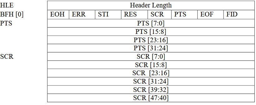
Basic Header Fields
All Payload Headers start with two core bytes:
HLE (Header Length): 1 byte. Specifies the length of the entire header (in bytes), including HLE itself, BFH, and optional PTS/SCR fields.
BFH[0] (Bit Field Header): 1 byte. Bit field flags indicating attributes of subsequent data and the presence of optional fields.
BFH[0] Bit Field Definition
Bit
Name
Description
D0
FID
Frame Identifier. Used to distinguish different video frames or segments (behavior depends on video format, see below).
D1
EOF
End of Frame. Indicates whether the current packet is the last packet of a frame or segment.
D2
PTS
Presentation Time Stamp. When set to 1, indicates the header contains a 4-byte PTS field.
D3
SCR
Source Clock Reference. When set to 1, indicates the header contains a 6-byte SCR field.
D4
RES
Reserved. Usually set to 0.
D5
STI
Still Image. Set to 1 indicates the sample belongs to a static image (Stream-based formats usually set to 0).
D6
ERR
Error Bit. Set to 1 indicates an error occurred on the device during streaming.
D7
EOH
End of Header. Set to 1 indicates the end of BFH fields (i.e., no extension header).
Optional Extension Fields
PTS (4 bytes): Exists when BFH[0].D2 (PTS) is set. Represents the presentation time of the video frame.
SCR (6 bytes): Exists when BFH[0].D3 (SCR) is set. Source clock reference used for audio/video synchronization.
Video Data Transmission Formats
In the UVC specification, video data transmission formats are mainly divided into two categories: Frame-based and Stream-based. These two modes determine how the host parses video data and processes the Payload Header.
Frame-based
This is the most common mode, applicable to MJPEG, Uncompressed (YUV/NV12), and other formats.
Characteristics: Video data is strictly divided into individual independent images (frames).
Transmission Logic: The host driver focuses on “frame boundaries”, assembling a complete frame by detecting the FID toggle or EOF flag in the Payload Header.
Stream-based
Mainly used for compressed stream formats like H.264/H.265.
Characteristics: Data is treated as a continuous byte stream without a strict physical “frame” boundary concept (or the boundary is handled internally by the decoder).
Transmission Logic: The host driver is mainly responsible for transporting the data stream, usually not relying on the Payload Header to determine the start or end of a frame, but passing the data directly to the upper-layer application or decoder to parse the content.
Note
Engineering Practice: Actual Behavior of Stream-based Devices
Although the UVC specification states that Stream-based formats may not use FID and EOF to delimit boundaries, in actual engineering applications:
Device Side (Camera):
Even when outputting Stream-based formats like H.264/H.265, the vast majority of manufacturers still try to follow Frame-based rules as much as possible, marking the boundaries of data blocks (such as NAL Units or frame slices) by toggling FID or setting EOF.
Host Side (Host):
To simplify logic, most generic UVC drivers (such as Linux uvcvideo, Windows system drivers) default to uniformly slicing data packets based on FID jumps or EOF flags.
Tip
Engineering Practice: Host Driver Data Processing Mechanism
In actual engineering implementation, the UVC Host Driver adopts a unified transmission processing strategy for Frame-based and Stream-based formats, without making special distinctions for stream transmission. Its core processing logic is as follows:
Format Independence of Transport Layer:
The driver layer is only responsible for data transport and reassembly and is not aware of the specific video encoding format or stream type. Regardless of the data type declared by the device descriptor, the driver treats it as a generic data payload.
Unified Packet Assembly Mechanism:
The driver strictly relies on the FID (Frame Identifier) state toggle and EOF (End of Frame) flag bit in the Payload Header for data delimitation. The driver assembles data packets belonging to the same logical sequence into a complete Payload Buffer and submits it to the user space as one frame at the driver level.
Separation of Parsing Responsibility:
Parsing of data content is the responsibility of the Application Layer.
For example, for Stream-based formats like H.264, the Buffer submitted by the driver may contain multiple NAL Units or partial frame data, and the application layer needs to parse the stream data structure itself to obtain the actual video frames.
Class Driver
This section describes in detail the internal implementation of the USB UVC host driver, including the driver architecture, video stream management, support status of class-specific requests, and the pipe resource allocation scheme.
Detailed Implementation
The USB UVC Host driver stack is based on a modular design, achieving efficient interaction between the upper-layer application and the USB hardware controller through a layered architecture. This architecture ensures stable capture and processing of high-bandwidth video data and provides a flexible frame buffer management mechanism.
The core architecture and data flow are shown in the figure below:


Divided by functional responsibilities, it consists of the following core modules:
Application Adapter
Responsible for buffering and retrieval of video frame data (Video Frame).
As the interface layer between the USB driver and the user application (User Application), it manages the final output of video data:
Parameter Configuration: Provides the
usbh_uvc_set_param()API to allow the application layer to configure resolution, frame rate, and video format.Data Acquisition: Provides the
usbh_uvc_get_frame()API. The application layer uses this API to obtain fully assembled video frames from the ready queue (Ready Queue).Stream Control: Provides the
usbh_uvc_stream_on()andusbh_uvc_stream_off()APIs to control the start and stop of the underlying video stream transmission.
UVC Class Driver Architecture
On the host side, the UVC driver is implemented by the UVC class protocol driver (UVC Class Driver), which is responsible for standard protocol handshakes, descriptor topology parsing, and video stream maintenance.
This module implements core functionality based on the USB Video Class 1.1 specification, with minimal UVC 1.5 compatibility — only the necessary negotiation fields defined in UVC 1.5 are recognized for device interoperability, while extended features introduced in UVC 1.5 beyond UVC 1.1 are not supported. This module thereby implements the core business logic for interaction between the host and UVC devices. Its main responsibilities include:
Enumeration and Interface Binding: Parses the Video Control Interface (VC Interface) and Video Streaming Interface (VS Interface) to establish the internal UVC topology (such as Units and Terminals).
Format Negotiation (Probe & Commit): Before the video stream starts, executes the standard Probe/Commit procedure to negotiate resolution, frame rate, and optimal bandwidth settings with the device.
Bandwidth Allocation: Before the video stream starts, selects an appropriate Video Streaming interface alternate setting (Alt Setting) based on the Probe/Commit negotiation result, and requests the corresponding endpoint bandwidth resources from the USB stack during configuration. The current version only supports isochronous transfer mode and does not support bulk video streams.
Core Processing Task (Process Task)
Responsible for the core logic and state machine management of the USB protocol stack.
State Machine Maintenance: Manages UVC-specific state transitions, including
UVC_STATE_CTRL(control transfer handling),UVC_STATE_TRANSFER(data transfer handling), and state transitions during stream start-up.Event Handling: Responds to transfer completion events reported by the lower layer and coordinates the timing between control transfers and data transfers.
Dynamic Hot-Plug Handling: Handles device attach and detach events and automatically releases stream buffers and pipe resources upon device removal.
Frame Assembly Service
The software driver is responsible for parsing, reassembling, and error checking of raw USB packets.
URB Handling: Receives URB (USB Request Block) packets reported by the lower layer and parses the UVC payload header.
Frame Assembly: Handles FID (Frame ID) toggle logic, strips protocol headers, and fills the valid video payload into the frame buffer.
Error Detection: Parses the
bmHeaderInfofield in the UVC payload header to check theERRflag and other error information. In conjunction with the FID state, determines frame boundaries to ensure the integrity of video frame data. When hardware acceleration is enabled, this module interfaces directly with the hardware decoder.
An internal UVC hardware module is responsible for parsing, reassembling, and error checking of raw USB packets. This can significantly reduce CPU load.
Class-Specific Request Implementation
The driver stack follows the USB Video Class specification and encapsulates the implementation and transmission flow of the core class-specific requests (Class-Specific Requests).
The current driver mainly implements class-specific requests related to Video Probe Control and Video Commit Control (SET_CUR/GET_CUR). Source code path: {SDK}/component/usb/host/uvc
Class-Specific Request Type |
Remarks |
|---|---|
SET_CUR |
Sets the current attribute. Mainly used in Probe and Commit phases to send desired video stream parameters (e.g., |
GET_CUR |
Gets the current attribute. Reads the currently active configuration parameters from the device, used to verify settings or retrieve current status. |
Pipe Configuration
During device enumeration (usbh_uvc_attach), the UVC host driver parses the configuration descriptor, automatically identifies the video control and video streaming interfaces, and requests the corresponding pipe resources according to the Alt Setting.
Pipe Type |
Description |
|---|---|
Control IN/OUT Pipe |
Default Control Pipe 0 (EP0). Used for sending standard requests and UVC specific requests (e.g., Video Probe and Commit Control). |
Isochronous IN Pipe |
Belongs to the Video Streaming Interface (VS Interface). Used for receiving high-bandwidth video payload data. The driver supports automatically selecting the appropriate Packet Size (MPS) and transfer mode based on USB speed (Full/High Speed). |
API Reference
Application Example
Application Design
This section describes in detail the complete development process of the UVC (USB Video Class) host driver, covering driver initialization, hot-plug management, video stream control and data processing, as well as example descriptions for different application scenarios.
Driver Initialization
Before using the UVC host driver, you need to define the UVC configuration structure (such as usbh_uvc_cfg_t) and register the callback structure usbh_uvc_cb_t, then call the core interfaces in sequence to start the USB host stack and the UVC class driver.
Step description:
Hardware Configuration: Set the USB speed mode and related interrupt priorities.
Callback Registration: Define the
usbh_uvc_cb_tstructure and register handler functions for various stages (initialization, connection, disconnection, parameter setting completion).Core Initialization: Call
usbh_init()to initialize the USB core stack.Class Driver Loading: Call
usbh_uvc_init()to initialize the UVC class driver.
/*
 * 1. Configure USB speed, ISR priority, and main task priority.
 */
static usbh_config_t usbh_cfg = {
        .speed = USB_SPEED_HIGH,
        .ext_intr_enable = USBH_SOF_INTR,
        .isr_priority = INT_PRI_MIDDLE,
        .main_task_priority = CONFIG_USBH_UVC_MAIN_THREAD_PRIORITY,
        .tick_source = USBH_SOF_TICK,
};

/*
 * 2. Configure UVC user-level HW priority.
 */
static usbh_uvc_ctx_t uvc_cfg = {
#if USBH_UVC_USE_HW
        .hw_isr_pri = CONFIG_USBH_UVC_HW_IRQ_PRIORITY,
#endif
};

/*
 * 3. Define user callbacks for UVC events.
 */
static usbh_uvc_cb_t uvc_cb = {
        .init = uvc_cb_init,
        .deinit = uvc_cb_deinit,
        .attach = uvc_cb_attach,
        .detach = uvc_cb_detach,
        .setup = uvc_cb_setup,
        .setparam = uvc_cb_setparam,  /* int status: check uvc_setparam_status after semaphore */
};

int ret = 0;

/*
 * 4. Initialize USB host core driver with configuration.
 */
ret = usbh_init(&usbh_cfg, NULL);
if (ret != HAL_OK) {
        goto free_sema_exit;
}

/*
 * 5. Initialize UVC class driver.
 */
ret = usbh_uvc_init(&uvc_cfg, &uvc_cb);
if (ret != HAL_OK) {
        /* If class driver init fails, clean up the core driver */
        usbh_deinit();
        goto usb_deinit_exit;
}
Hot-Plug Event Handling
Monitor UVC camera connection and disconnection by registering the attach and detach callbacks in usbh_uvc_cb_t.
In the example code, a semaphore mechanism is used to synchronize states:
Attach: When a camera is inserted and successfully enumerated, the
attachcallback is triggered, releasinguvc_attach_semato notify the main thread to create the video capture task.Detach: When the camera is removed, the
detachcallback is triggered, releasinguvc_detach_semato wake up the hot-plug management thread (uvc_hotplug_thread) to perform resource cleanup and re-initialization.
/* USB callback */
static usbh_uvc_cb_t uvc_cb = {
        .attach = uvc_cb_attach,
        .detach = uvc_cb_detach,
};

/* Callback executed when device is inserted */
static int uvc_cb_attach(void)
{
        USB_DIAG(USB_LAYER_APP, USB_EVT_LINK, 2);
        rtos_sema_give(uvc_attach_sema);
        return HAL_OK;
}

/* Callback executed when device is removed */
static int uvc_cb_detach(void)
{
        USB_DIAG(USB_LAYER_APP, USB_EVT_LINK, 3);
#if CONFIG_USBH_UVC_HOT_PLUG
        rtos_sema_give(uvc_detach_sema);
#endif
        return HAL_OK;
}

/* Thread Context: Handle the state machine for Hotplug */
static void example_usbh_uvc_hotplug_thread(void *param)
{
        int ret = 0;

        UNUSED(param);

        for (;;) {
                /* Wait for detach signal */
                if (rtos_sema_take(uvc_detach_sema, RTOS_SEMA_MAX_COUNT) == RTK_SUCCESS) {

                        /* Step 1: Set exiting flag so uvc_test can exit gracefully */
                        uvc_task_exiting = 1;

                        /* Step 2: Let uvc_test finish processing the current frame */
                        /* (img_prepare + put_frame) before tearing down stream resources */
                        rtos_time_delay_ms(200);

                        /* Step 3: Stop streaming to wake up any blocked get_frame call.
                        /* After this, get_frame returns NULL (stream_state != STREAMING_ON). */
                        usbh_uvc_stream_off(CONFIG_USBH_UVC_IF_NUM_0);

                        /* Step 4: Wait for uvc_test to detect flag, break out of loop, and self-delete.*/
                        /* No timeout: must not deinit while uvc_test is still running,*/
                        /* as it may call usbh_uvc_put_frame() on already-freed memory. */
                        while (uvc_task != NULL) {
                                rtos_time_delay_ms(100);
                        }

                        RTK_LOGS(TAG, RTK_LOG_INFO, "Hotplug: uvc_test exited\n");

                        /* Step 5: De-init UVC Class and Host Core */
                        usbh_uvc_deinit();
                        usbh_deinit();
                        rtos_time_delay_ms(10);
                        RTK_LOGS(TAG, RTK_LOG_INFO, "Free heap: 0x%x\n", rtos_mem_get_free_heap_size());

                        /* Reset exiting flag before re-init */
                        uvc_task_exiting = 0;

                        /* Step 6: Re-init Host Core and UVC Class for next attach */
                        ret = usbh_init(&usbh_cfg, NULL);
                        if (ret != HAL_OK) {
                                RTK_LOGS(TAG, RTK_LOG_ERROR, "Init USBH fail\n");
                                break;
                        }

                        ret = usbh_uvc_init(&uvc_cfg, &uvc_cb);
                        if (ret < 0) {
                                RTK_LOGS(TAG, RTK_LOG_ERROR, "Init UVC fail\n");
                                usbh_deinit();
                                break;
                        }
                }
        }

        RTK_LOGS(TAG, RTK_LOG_ERROR, "Hotplug thread fail\n");
        rtos_task_delete(NULL);
}

/* Main entry task to initialize USB and wait for connection */
static void example_usbh_uvc_task(void *param)
{
        rtos_task_t hotplug_task;
        int ret = 0;

        /* ... Initialization of semaphores and mutexes ... */

        /* Init USB Host Core */
        ret = usbh_init(&usbh_cfg, NULL);
        if (ret != HAL_OK) {
                goto free_sema_exit;
        }

        /* Init UVC Class Driver */
        ret = usbh_uvc_init(&uvc_cfg, &uvc_cb);
        if (ret != HAL_OK) {
                usbh_deinit();
                goto usb_deinit_exit;
        }

        /* Create Hotplug detection thread */
        ret = rtos_task_create(&hotplug_task, "example_usbh_uvc_hotplug_thread", example_usbh_uvc_hotplug_thread, NULL, 768U, CONFIG_USBH_UVC_HOTPLUG_THREAD_PRIORITY);
        if (ret != RTK_SUCCESS) {
                goto usbh_uvc_deinit_exit;
        }

        /* Wait for device attach callback to release semaphore */
        while (1) {
                if (rtos_sema_take(uvc_attach_sema, RTOS_SEMA_MAX_COUNT) == RTK_SUCCESS) {
                        if (uvc_task == NULL) {
                                /* Create the main UVC test/streaming thread */
                                ret = rtos_task_create(&uvc_task, "example_usbh_uvc_test", example_usbh_uvc_test, NULL,
                                                                           768U, CONFIG_USBH_UVC_TEST_THREAD_PRIORITY);
                                if (ret != RTK_SUCCESS) {
                                        goto delete_hotplug_task_exit;
                                }
                        }
                }
        }
        goto example_exit;

        /* ... Error handling labels ... */
        ......
}
Video Stream Control and Data Processing
After the UVC device is successfully enumerated, the host needs to configure video parameters and start the video stream, then periodically acquire image frame data.
Frame Buffer Size Configuration
The CONFIG_USBH_UVC_FRAME_BUF_SIZE macro determines the size of each image frame buffer. Proper configuration of this value is critical for stable video capture. The recommended size depends on the video format, resolution, bitrate, and frame rate.
The average frame size can be estimated with the following formula:
avg_frame_size (KB) = bitrate (kbps) / framerate (fps) / 8
rec (KB) = avg_frame_size x margin
Where margin is a safety factor that varies by compression format:
Format |
Margin |
Explanation |
|---|---|---|
MJPEG |
3x |
Peak frame fluctuation. A 3x safety margin accommodates typical peak frames. |
H264 |
5x |
Peak I-frame size. I-frames are significantly larger than P/B-frames. Increase to 8x for high-motion scenes. |
YUY2 |
N/A |
No margin is needed. Frame size is fixed and uncompressed: width x height x 2 bytes. |
The following table provides reference calculations for common configurations:
Format |
Resolution |
Bitrate |
FPS |
Avg Size |
Recommended Buffer Size |
|---|---|---|---|---|---|
MJPEG |
720p (1280x720) |
10 Mbps |
30 |
41 KB |
125 KB (3 x 41 KB) |
MJPEG |
1080p (1920x1080) |
12 Mbps |
30 |
50 KB |
150 KB (3 x 50 KB) |
H264 |
720p (1280x720) |
8 Mbps |
30 |
33 KB |
166 KB (5 x 33 KB) |
H264 |
1080p (1920x1080) |
12 Mbps |
30 |
50 KB |
250 KB (5 x 50 KB) |
YUY2 |
480p (640x480) |
N/A |
30 |
600 KB |
600 KB (fixed: 640 x 480 x 2) |
YUY2 |
720p (1280x720) |
N/A |
30 |
1,800 KB |
1,800 KB (fixed: 1280 x 720 x 2) |
Note
Within USB 2.0 HS limits, YUY2 720p @ 30 fps (~442 Mbps) approaches the limit.
If an
oversizeerror occurs at runtime (Frame overflowlog), increaseCONFIG_USBH_UVC_FRAME_BUF_SIZE.Ensure the target hardware has sufficient heap memory for the configured buffer size.
Parameter Configuration (Set Parameters)
Before starting the video stream, call
usbh_uvc_set_param()to set the desired format (for example, MJPEG, H.264, YUY2, etc.), resolution, and frame rate. After the setting request is issued, you must wait for theuvc_setparam_semasemaphore to confirm that the parameter set has been successfully negotiated with the device via the Probe/Commit procedure and has taken effect.Start Video Stream (Stream On)
Call
usbh_uvc_stream_on()to start video transmission on the specified interface. The device will begin sending isochronous (Isochronous) data packets on the USB bus.Frame Data Acquisition and Processing
During the initialization phase, the image frame buffer pool is allocated uniformly by the driver, and its size is configured by the
CONFIG_USBH_UVC_FRAME_BUF_SIZEmacro. In the main loop, the application must strictly follow the “Get -> Process -> Put” workflow:Get (Get Frame):
Call
usbh_uvc_get_frame()to obtain one fully filled image frame from the driver.RTL8730E:Drop Oldest mechanism:
The driver maintains a frame buffer pool and provides frame-assembling services. When the processing speed of the application layer is slower than the data production speed, the driver automatically discards unread old frames in the queue to ensure that this interface always returns the latest image frame.
RTL8721F:Hardware frame assembling mechanism:
Frame assembling is performed directly by the underlying hardware. This hardware mechanism ensures that this interface can always obtain the latest image frame.
Process:
Consume the data in the application layer (for example, copy for display, save to file, upload over the network, or perform statistical analysis only).
Note
Data Processing Description:
The UVC driver, as a producer, delivers data to the consumer in units of frames (that is, all UVC payloads that together make up one complete image frame). The driver does not parse the specific encoded data content inside the UVC payload (such as MJPEG/H.264 bitstreams), so the application layer must implement payload decoding or processing logic by itself according to the specific video format.
Put Frame:
Regardless of how the application layer processes the frame (even if it only counts the data size or decides to discard the frame),
usbh_uvc_put_frame()must be called after processing is complete.Note
RTL8730E:This function is used to return the buffer to the driver’s internal frame pool. If the buffer is not returned in a timely manner, the frame buffer pool will be exhausted and no new image data can be acquired.
RTL8721F:This function does not perform any actual operation. If the consumer in the upper-layer application is too slow, the HW UVC module will internally overwrite old data with new frames.
Stop Video Stream (Stream Off)
When video data is no longer needed or before disconnecting, call
usbh_uvc_stream_off(). This notifies the device to stop isochronous (ISOC) transmission, releases isochronous endpoint bandwidth, and resets the driver’s internal stream control state.
/* Define user callbacks for UVC events */
static usbh_uvc_cb_t uvc_cb = {
        .setup = uvc_cb_setup,
        .setparam = uvc_cb_setparam,
};

/* Define USB user-level setup callback */
static int uvc_cb_setup(void)
{
        USB_DIAG(USB_LAYER_APP, USB_EVT_LINK, 4);
        rtos_sema_give(uvc_start_sema);
        return HAL_OK;
}

/* Define USB user-level setparam callback */
static int uvc_cb_setparam(int status)
{
        USB_DIAG(USB_LAYER_APP, USB_EVT_LINK, 5);
        uvc_setparam_status = status;
        rtos_sema_give(uvc_setparam_sema);
        return HAL_OK;
}

/* Main UVC Test Thread */
static void example_usbh_uvc_test(void *param)
{
        ......

        /* Wait for the device to be ready (Enumeration Complete) */
        while (!uvc_task_exiting) {
                if (rtos_sema_take(uvc_start_sema, RTOS_SEMA_MAX_COUNT) != RTK_SUCCESS) {
                        continue;
                }
                /* 1. Configure UVC Parameters */
                /* Set the desired format, resolution, and frame rate */
                uvc_s_ctx.fmt_type = CONFIG_USBH_UVC_FORMAT_TYPE; // e.g., MJPEG
                uvc_s_ctx.width = CONFIG_USBH_UVC_WIDTH;          // e.g., 1080
                uvc_s_ctx.height = CONFIG_USBH_UVC_HEIGHT;        // e.g., 720
                uvc_s_ctx.frame_rate = CONFIG_USBH_UVC_FRAME_RATE;// e.g., 30
                uvc_s_ctx.frame_buf_size = CONFIG_USBH_UVC_FRAME_BUF_SIZE;

                if (uvc_s_ctx.fmt_type == USBH_UVC_FORMAT_MJPEG) {
                        fmt_name = "MJPEG";
                } else if (uvc_s_ctx.fmt_type == USBH_UVC_FORMAT_H264) {
                        fmt_name = "H264";
                } else if (uvc_s_ctx.fmt_type == USBH_UVC_FORMAT_YUV) {
                        fmt_name = "YUV";
                } else {
                        RTK_LOGS(TAG, RTK_LOG_ERROR, "Unsupport type %d\n", uvc_s_ctx.fmt_type);
                        goto exit;
                }

                /* Trigger the UVC parameter setting process */
                ret = usbh_uvc_set_param(&uvc_s_ctx, CONFIG_USBH_UVC_IF_NUM_0);
                if (ret != RTK_SUCCESS) {
                        RTK_LOGS(TAG, RTK_LOG_ERROR, "Set param req failed: %d\n", ret);
                        goto exit;
                }

                /* Wait for the semaphore indicating parameter setting is actually completed */
                if (rtos_sema_take(uvc_setparam_sema, 5000) == RTK_SUCCESS) {
                        /* Check the status returned by the setparam callback */
                        if (uvc_setparam_status != HAL_OK) {
                                RTK_LOGS(TAG, RTK_LOG_ERROR, "Set paras err: %s %d*%d@%dfps status=%d\n",
                                                fmt_name, uvc_s_ctx.width, uvc_s_ctx.height, uvc_s_ctx.frame_rate, uvc_setparam_status);
                                goto exit;
                        }
                        RTK_LOGS(TAG, RTK_LOG_INFO, "Set paras ok: %s %d*%d@%dfps\n",
                                        fmt_name, uvc_s_ctx.width, uvc_s_ctx.height, uvc_s_ctx.frame_rate);
                } else {
                        RTK_LOGS(TAG, RTK_LOG_ERROR, "Set paras timeout: %s %d*%d@%dfps\n",
                                        fmt_name, uvc_s_ctx.width, uvc_s_ctx.height, uvc_s_ctx.frame_rate);
                        goto exit;
                }

                /* ... Initialize consumer tasks (e.g., VFS thread or HTTPC thread) ... */

                /* 2. Start Video Stream */
                RTK_LOGS(TAG, RTK_LOG_INFO, "Stream on\n");
                ret = usbh_uvc_stream_on(&uvc_s_ctx, CONFIG_USBH_UVC_IF_NUM_0);
                if (ret) goto exit;

                /* 3. Main Capture Loop */
                while (img_cnt < CONFIG_USBH_UVC_LOOP && !uvc_task_exiting) {

                        // 3.1 Get Frame from USB Stack
                        /* Retrieve a filled frame buffer from the UVC driver */
                        buf = usbh_uvc_get_frame(CONFIG_USBH_UVC_IF_NUM_0);

                        if (buf == NULL) {
                                /* Frame not ready yet, fail_cnt ++ , wait and retry */
                                rtos_time_delay_ms(1);
                                continue;
                        }

                        // 3.2 Process the Frame Data
                        /* CRITICAL: Buffer overflow detected! */
                        /* This means the camera sent a frame larger than our allocated buffer. */
                        /* ACTION: Please increase 'CONFIG_USBH_UVC_FRAME_BUF_SIZE' in example_usbh_uvc.c */
                        /* to match the camera's actual output size for the current resolution/format. */

                        len = buf->byteused;

                        /* Even on error, we must return the frame buffer */
                        if (len > CONFIG_USBH_UVC_FRAME_BUF_SIZE) {
                                if (usbh_uvc_put_frame(buf, CONFIG_USBH_UVC_IF_NUM_0) != HAL_OK) {
                                        RTK_LOGS(TAG, RTK_LOG_ERROR, "Put frame fail\n");
                                }
                                RTK_LOGS(TAG, RTK_LOG_ERROR, "Frame %d overflow %d > %d\n", img_cnt, len, CONFIG_USBH_UVC_FRAME_BUF_SIZE);
                                goto exit;
                        }

                        /* CONSUMER LOGIC: */
                        /* The actual data processing happens here. */
                        /* - Simple Mode:  Just count bytes and drop data. */
                        /* - VFS Mode: Write `buf->buf` to SD Card. */
                        /* - HTTPC Mode: Send `buf->buf` to Network. */
                        if (len > 0) {
                                RTK_LOGS(TAG, RTK_LOG_INFO, "Captured frame %d, len=%d\n", img_cnt, len);
                                usbh_uvc_img_prepare(buf);
                        }

                        // 3.3 Put Frame back to USB Stack
                        /* CRITICAL: Must return the buffer to driver for the next capture */
                        if (usbh_uvc_put_frame(buf, CONFIG_USBH_UVC_IF_NUM_0) != HAL_OK) {
                                RTK_LOGS(TAG, RTK_LOG_ERROR, "Put frame fail\n");
                        }
                        img_cnt ++;
                }

                /* 4. Calculate throughput */
                uvc_calculate_tp(img_cnt);

                /* 5. Release source when detech*/
                if (uvc_task_exiting) {
                        ......
                        goto exit;
                }
        }

/* exit labels */
}
Driver De-initialization
When the device is disconnected or the USB host function needs to be disabled, the class driver and the host core driver must be unloaded in order, and related system resources must be released.
/* 1. Deinitialize UVC class driver. */
usbh_uvc_deinit();

/* 2. Deinitialize USB host core driver */
usbh_deinit();
Operation method
This example demonstrates how Ameba, acting as a USB UVC host, captures video frames from a camera. To meet different application scenarios, the example provides three working modes:
Macro |
Description |
Frame Storage / Upload Method |
|---|---|---|
|
Basic Test Mode |
Video frames are captured only for throughput statistics,
without post-processing;
each session captures |
|
SD Card Storage Mode |
Video frames are written to an SD card (FAT32) via VFS;
MJPEG: frames are saved as |
|
Network Upload Mode |
Video frames are uploaded to an HTTP server via HTTP POST: Ringbuffer (RTL8730E, SW UVC)
MJPEG: uploaded frame by frame;
H264: uploaded in chunked streaming mode;
PSRAM (RTL8721F, HW UVC) Frames are captured within a time window and uploaded in batch (approximately 2 seconds of video). |
Users can select the active mode by modifying the CONFIG_USBH_UVC_APP macro definition in the code.
Configuration and Compilation
Software Configuration
Open the
example_usbh_uvc.cfile and modify theCONFIG_USBH_UVC_APPmacro definition according to the test requirements:/* Supported application example: USBH_UVC_APP_SIMPLE, USBH_UVC_APP_VFS, USBH_UVC_APP_HTTPC */ #define CONFIG_USBH_UVC_APP USBH_UVC_APP_SIMPLE /* Supported formats: USBH_UVC_FORMAT_MJPEG, USBH_UVC_FORMAT_YUV, USBH_UVC_FORMAT_H264 * Note: Users must verify which formats their specific camera supports and * adjust the definition below accordingly. */ #define CONFIG_USBH_UVC_FORMAT_TYPE USBH_UVC_FORMAT_MJPEG /* Target resolution and compression ratio. * If the specific camera device does not support * these values, the host stack will automatically select the closest match. * Always check the logs to confirm the actual parameters applied. */ #define CONFIG_USBH_UVC_WIDTH 1280 #define CONFIG_USBH_UVC_HEIGHT 720 #define CONFIG_USBH_UVC_FRAME_RATE 30 /* Frame buffer size in bytes * Size depends on format, resolution, and scene complexity. * Formula: * avg_frame_size (KB) = bitrate (kbps) / framerate (fps) / 8 * rec = avg x margin * * Margin by format: * MJPEG: 3 x avg (peak frame fluctuation) * H264: 5 x avg (peak I-frame; increase to 8x for high-motion) * YUY2: no margin needed, set to width x height x 2 (uncompressed, fixed frame size) * * Examples: * MJPEG @ 720p 30 fps, 10 Mbps : avg = 41 KB, rec = 125 KB * MJPEG @ 1080p 30 fps, 12 Mbps : avg = 50 KB, rec = 150 KB * H264 @ 720p 30 fps, 8 Mbps : avg = 33 KB, rec = 166 KB * H264 @ 1080p 30 fps, 12 Mbps : avg = 50 KB, rec = 250 KB * YUY2 @ 480p 30 fps : frame = 640 x 480 x 2 = 600 KB (USB 2.0 bandwidth: 147 Mbps) * YUY2 @ 720p 30 fps : frame = 1280 x 720 x 2 = 1,800 KB (USB 2.0 bandwidth: 442 Mbps) * YUY2 @ 1080p 30 fps : not listed - exceeds USB 2.0 HS bandwidth (~480 Mbps theoretical); * 1080p YUY2 @ 30 fps requires ~950 Mbps; use MJPEG or H264 instead. * Note: Increase this value if an oversize error occurs; Ensure the target hardware has * sufficient heap memory for this buffer. */ #define CONFIG_USBH_UVC_FRAME_BUF_SIZE (150 * 1024) /* Most cameras have a single video stream interface, so use default 0. * If the camera supports dual streams, set this to 1. * Note: Current protocol stack supports a maximum of 2 video stream interfaces. */ #define CONFIG_USBH_UVC_IF_NUM_0 0 /* Hot plug / memory leak test */ #define CONFIG_USBH_UVC_HOT_PLUG 1 /* Check image data validity (0: Disable, 1: Enable) */ #define CONFIG_USBH_UVC_CHECK_MJEPG_DATA 1 /* Number of frames to capture in the loop */ #define CONFIG_USBH_UVC_LOOP 200 /* Maximum continuous error count before stopping */ #define CONFIG_USBH_UVC_MAX_FAIL_COUNT 5
Depending on the selected mode, also pay attention to the following configuration items:
If using HTTPC mode, configure the target server’s IP address and port, and ensure the Wi-Fi connection information is correct.
#define USBH_UVC_HTTPC_SERVER            "xx.xx.xx.xx"
#define USBH_UVC_HTTPC_PORT              5090
Compilation and Flashing
Execute the following commands in the SDK root directory to configure the environment, select the target SoC, compile the project, and flash the generated
Imagefile to the development board:# Initialize environment (required for every new terminal) source env.sh or env.bat(Windows system) # Select Target SoC (replace xxx with your specific SoCs) ameba.py soc xxx ameba.py build -a usbh_uvc -p
Confirmation of Menuconfig configuration
If compilation fails, run
ameba.py menuconfigand confirm thatUSBH UVChas been selected.- Choose `CONFIG USB --->`: [*] Enable USB USB Mode (Host) ---> [*] UVC
Result Verification
General Test Steps:
Connect the USB camera to the USB interface of the development board.
Reset the development board and observe the serial logs.
Ensure there are no USB-related error messages (e.g., enumeration failure).
Check the specific verification steps and expected logs below according to the selected mode:
Test Description:
In this mode, after the system detects the camera, it periodically captures images (default 200 frames), only calculating throughput without saving data.
Expected Log:
[UVC-I] Set paras ok: MJPEG 1280*720@60fps
[UVC-I] Stream on
[UVC-I] Captured frame 0, len=20832
[UVC-I] Captured frame 1, len=20912
...
[UVC-I] Captured frame 199, len=108264
[UVC-I] TP 4126 KB/s @ 4953 ms, fps 40/s
[UVC-I] TP 4.0 MB/s-40 (0_20930888/200)
[UVC-I] Stream off
[UVC-I] Test done
Test Description:
Be sure to insert an SD card formatted as FAT32 before resetting.
After the test is complete, insert the SD card into a computer and check whether
imgX.jpegfiles are generated and can be opened normally.
Expected Log:
[UVC-I] Set paras ok: MJPEG 1280*720@60fps
[UVC-I] Start vfs service
...
[UVC-I] VFS-SDcard Init Success
[UVC-I] Stream on
[UVC-I] Captured frame 0, len=25952
[UVC-I] Create image file: sdcard:img0.jpeg
[UVC-I] fwrite() ok, w 25946
[UVC-I] Captured frame 1, len=24904
[UVC-I] Create image file: sdcard:img1.jpeg
Buffer Mode Description:
The HTTPC mode provides two buffer modes configured by USBH_UVC_HTTPC_BUFFER_MODE:
Mode |
Storage |
Behavior |
Typical SoC |
Memory Footprint |
|---|---|---|---|---|
0 |
Ring Buffer (SRAM) |
Frame data is stored in a ring buffer allocated from internal SRAM, and the HTTP client uploads frames in real time (MJPEG: per-frame upload; H264: streaming upload). |
RTL8730E (software UVC) |
SRAM: |
1 |
PSRAM |
Frame data is written to an external PSRAM buffer during capture. After capture completes, the HTTP client uploads the entire PSRAM content as a single batch. |
RTL8721F (hardware UVC) |
PSRAM: 2 MB |
The mode is selected automatically based on the SoC:
RTL8730E (SW UVC):
USBH_UVC_HTTPC_BUFFER_MODE= 0, uses SRAM ring buffer for real-time upload.RTL8721F (HW UVC):
USBH_UVC_HTTPC_BUFFER_MODE= 1, uses PSRAM buffer for post-capture batch upload.
Runtime CLI Command:
The HTTPC server IP can be changed at runtime without recompiling using the uvch_setip CLI command:
# Set HTTPC server IP (must be done before WiFi connection)
uvch_setip xx.xx.xx.xx
Environment Setup:
Before testing, set up an Apache server on the PC to receive images.
Install Apache: Download and unzip Apache24, modify
SRVROOTinconf/httpd.confto the unzipped path, and set theListenport to 5090.Configure the upload script: Create
submit.pyinApache24/cgi-bin/(ensure the Python path in the first line is correct):
#!C:\Programs\Python\Python312\python.exe
#!/usr/bin/python3
# -*- coding: utf-8 -*-

import cgi, os
import cgitb

cgitb.enable()

form = cgi.FieldStorage()

# get filename
fileitem = form['filename']

# check
if fileitem.filename:
	fn = os.path.basename(fileitem.filename)
	open('../uploads/' + fn, 'wb').write(fileitem.file.read())

	message = 'file "' + fn + '" upload success'

else:
	message = 'file upload fail'

print("Content-Type: text/html")
print()
print("""
<html>
<head>
	<meta charset="utf-8">
<title>rtk.upload.com</title>
</head>
<body>
<p>%s</p>
</body>
</html>
""" % message)
Start the service: Run
Apache24/bin/httpd.exe.
Expected Log:
[UVC-I] Set paras ok: MJPEG 1280*720@60fps
[UVC-I] Start HTTP client
[UVC-I] Try to conn
[UVC-I] Start httpc
[UVC-I] Stream on
[UVC-I] Captured frame 0, len=20448
[UVC-I] Captured frame 1, len=19000
[UVC-I] Send image0 request ok
[UVC-I] Captured frame 2, len=19008
[UVC-I] Captured frame 3, len=24104
[UVC-I] Captured frame 4, len=24056
[UVC-I] Captured frame 5, len=71792
[UVC-I] Captured frame 6, len=72032
[UVC-I] Captured frame 7, len=71480
[UVC-I] Captured frame 8, len=71536
[UVC-I] Captured frame 9, len=71376
[UVC-I] Send image1 request ok
Result Check:
Check the Apache24/uploads directory on the PC (created/written by the submit.py script) to confirm that the images have been successfully uploaded.
Reviewing Captured Media:
JPEG images: Open directly with any image viewer on your PC.
JPEG sequence to MP4: Use
ffmpegto convert a JPEG frame sequence into a playable MP4 video, replace<framerate>with your actual frame rate and<drive>:with the SD card drive letter on your system:ffmpeg -framerate <framerate> -i <drive>:/img%d.jpeg -c:v libx264 -pix_fmt yuv420p output.mp4
H.264 raw stream: Use
ffplayto play the raw H.264 elementary stream directly:ffplay -f h264 stream.h264
YUY2 raw video: Can be played with VLC or
ffplay, specify rawvideo parameters such as pixel format, resolution, and framerate:ffplay -f rawvideo -pixel_format yuyv422 -video_size <resolution> -framerate <framerate> raw.yuv
Note
The above commands are for reference only. For the full command syntax and available options, refer to the FFmpeg documentation .
