Transparent Communication Host Solution
Overview
The Abstract Control Model (ACM) under the USB Communication Device Class (CDC) is based on the USB Bulk Transfer mechanism and defines a set of universal data interaction standards. In Host mode, the system utilizes this protocol to establish a high-speed data channel with external devices, enabling bidirectional transparent transmission of raw data streams.
The Ameba platform integrates a USB-IF compliant CDC ACM protocol stack, capable of efficient data transparent transmission capabilities.

Features
Supports hot plugging
Automatically parse descriptors and adapt to speed modes
Batch transmission length and other parameters are configurable
Support transparent transmission of raw data (text, binary, custom protocols, etc.)
Support for independently identifying and driving the serial port functionality within composite devices (such as ACM + HID)
Application Scenarios
As a USB CDC ACM host, Ameba can establish a point-to-point communication link with devices through the USB interface, and combine its wireless capability to expand various data transparent transmission applications, such as:
Wireless Data Transparent Transfer Bridge: Ameba, as a gateway, can be mounted with an external proprietary protocol dongle or acquisition module to transparently forward the raw data stream received on the USB side to a Wi-Fi or Bluetooth network, achieving seamless bridging and protocol conversion of wired data streams to wireless networks.
Empowering Traditional Industrial Equipment: Ameba connects to PLCs, CNC machines, or precision instruments via a USB-to-serial adapter, enabling protocol conversion and cloud access for traditional RS-232/485 devices. This facilitates the digital and intelligent upgrade of old production lines at a low cost.
High-speed data acquisition: Ameba connects to high-frequency sensors or acquisition cards equipped with USB interfaces, utilizing a bulk transfer mechanism to process large volumes of raw data in real-time. This breaks through the bandwidth bottleneck of traditional low-speed interfaces, ensuring data integrity and real-time performance in high-frequency sampling scenarios.
Protocol Introduction
CDC (Communication Device Class) is a standard for general communication devices defined by the USB specification. Within its PSTN (Public Switched Telephone Network) subclass, the most commonly used is ACM (Abstract Control Model). It defines a standardized set of commands for controlling communication parameters, such as:
Set baud rate (such as 9600, 115200)
Configure data bits, stop bits, and parity bits
Control DTR/RTS and other line status signals
It is through ACM that a USB CDC device can be recognized by the host as a standard “virtual serial port”.
Protocol Document
The USB-IF has officially released the CDC (Class Driver Control) basic protocol and PSTN (Public Switched Telephone Network) sub-class specifications. During the development process, please refer to the following core documents:
Specification type |
Document |
|---|---|
CDC (Communication Device Class Basic Protocol) |
|
PSTN (PSTN Subclass) |
PSTN specification is included in the aforementioned CDC zip file. |
Protocol Framework
The CDC ACM architecture utilizes a dual-interface mechanism to separate control flow from data flow, and logically binds them into a single functional unit via the Union Functional Descriptor.
Communication Class Interface (CCI)
Responsible for device management control and signaling interaction.
Control transmission: Transmit specific requests through the default control endpoint.
The host primarily sends PSTN control commands, with core instructions including SetLineCoding for configuring baud rate/data bits, and SetControlLineState for controlling RTS/DTR handshake signals.
Interrupt transmission: Utilizing interrupt input endpoints to achieve asynchronous status notification from the device to the host.
A typical application is to report changes in hardware signal status such as DCD, DSR, or Ring in real-time through SERIAL_STATE.
Data Class Interface (DCI)
Responsible for carrying application-layer payload data streams. This interface is typically configured as a pair of bulk endpoints (Bulk IN/Bulk OUT), serving solely as a transparent data transmission channel without involving the parsing or processing of control commands.
Example of protocol interaction:

Descriptor Structure
In addition to adhering to standard USB descriptors (such as device descriptor, configuration descriptor, and endpoint descriptor), CDC ACM devices also define Class-Specific Functional Descriptors to specify the capabilities of the abstract control model.
CDC ACM Descriptor Topology
The following example illustrates the descriptor topology using a High Speed configuration.
Device Descriptor
└── Identifies basic device information (Class: 0x02 CDC, SubClass: 0x02 ACM)

Configuration Descriptor
├── Includes total length, power attributes (Self-powered), etc.
│
├── Communication Class Interface Descriptor (Interface 0)
│   ├── Standard Interface Descriptor (Class: 0x02, SubClass: 0x02, Protocol: 0x01 AT Commands)
│   │
│   ├── Class-Specific Functional Descriptors (Defines ACM capabilities)
│   │   ├── Header Functional Descriptor (Declares CDC Spec version)
│   │   ├── Call Management Functional Descriptor (Call handling capabilities)
│   │   ├── ACM Functional Descriptor (Line coding & state capabilities)
│   │   └── Union Functional Descriptor (Binds Interface 0 and Interface 1)
│   │
│   └── Standard Endpoint Descriptor (Interrupt IN)
│       └── Used for Serial State notifications
│
├── Data Class Interface Descriptor (Interface 1)
│   ├── Standard Interface Descriptor (Class: 0x0A Data, SubClass: 0x00, Protocol: 0x00)
│   │
│   ├── Standard Endpoint Descriptor (Bulk OUT)
│   │   └── Host -> Device Data Stream
│   │
│   └── Standard Endpoint Descriptor (Bulk IN)
│       └── Device -> Host Data Stream
│
├── Device Qualifier Descriptor
│   └── Device information for other speed modes
│
└── Other Speed Configuration Descriptor
    └── Configuration information for Full Speed mode
Functional Descriptor
In the communication interface, the CDC must include the following special “function descriptor” header:
Header Functional Descriptor: Indicates the CDC version.
Call Management Functional Descriptor: Indicates how the device handles call management.
Abstract Control Management Functional Descriptor: Indicates which commands (such as Set_Line_Coding) are supported.
Union Functional Descriptor: specifies which one is the Master interface and which one is the Slave interface.
Header Functional Descriptor
Header Functional Descriptor
├── bLength            : 1 byte   → Total descriptor length (Fixed = 5 bytes)
├── bDescriptorType    : 1 byte   → 0x24 (CS_INTERFACE: Class-Specific Interface)
├── bDescriptorSubtype : 1 byte   → 0x00 (HEADER)
└── bcdCDC             : 2 bytes  → USB Class Definitions for Communication Devices Specification Release Number
                                    • 0x0110 = Release 1.10 (Common for ACM)
Call Management Functional Descriptor
Call Management Functional Descriptor
├── bLength            : 1 byte   → Total descriptor length (Fixed = 5 bytes)
├── bDescriptorType    : 1 byte   → 0x24 (CS_INTERFACE)
├── bDescriptorSubtype : 1 byte   → 0x01 (CALL_MANAGEMENT)
├── bmCapabilities     : 1 byte   → The capabilities that this configuration supports:
│                                   • Bit 0 = 0: Device does not handle call management itself
│                                   • Bit 0 = 1: Device handles call management itself
│                                   • Bit 1 = 0: Call management commands does not sent over Data Class Interface
│                                   • Bit 1 = 1: Call management commands can be sent over Data Class Interface
│                                   • Bits 2-7: Reserved (Reset to zero)
└── bDataInterface     : 1 byte   → Interface number of Data Class interface optionally used for call management
                                    (Zero if no data interface is used)
ACM Functional Descriptor
Abstract Control Management (ACM) Functional Descriptor
├── bLength            : 1 byte   → Total descriptor length (Fixed = 4 bytes)
├── bDescriptorType    : 1 byte   → 0x24 (CS_INTERFACE)
├── bDescriptorSubtype : 1 byte   → 0x02 (ABSTRACT_CONTROL_MANAGEMENT)
└── bmCapabilities     : 1 byte   → The capabilities that this configuration supports:
                                    • Bit 0: Comm_Feature (Supports Set_Comm_Feature, Clear_Comm_Feature, Get_Comm_Feature)
                                    • Bit 1: Line_Coding (Supports Set_Line_Coding, Set_Control_Line_State, Get_Line_Coding, Serial_State)
                                    • Bit 2: Send_Break (Supports Send_Break)
                                    • Bit 3: Network_Connection (Supports Network_Connection)
                                    • Bits 4-7: Reserved (Reset to zero)
Union Functional Descriptor
Union Functional Descriptor
├── bLength            : 1 byte   → Total descriptor length (3 + Number of slave interfaces)
├── bDescriptorType    : 1 byte   → 0x24 (CS_INTERFACE)
├── bDescriptorSubtype : 1 byte   → 0x06 (UNION)
├── bMasterInterface   : 1 byte   → The interface number of the Communication or Data Class interface
│                                   (Designated as the controlling interface for the union)
└── bSlaveInterface0   : 1 byte   → Interface number of the first subordinate interface in the union
│    ⋮
└── bSlaveInterface(N) : 1 byte   → Interface number of the last subordinate interface in the union
Note
For specifications regarding the CDC ACM transfer protocol, please refer to USB CDC ACM Specification 。
Class-Specific Requests
Control requests for CDC ACM devices are categorized into Standard Requests and Class-Specific Requests.
This section primarily introduces the class-specific requests unique to CDC ACM and utilized for implementing core functionalities such as serial port parameter configuration and flow control signal management for virtual serial ports.
Request Name |
Requirement |
Description |
|---|---|---|
SEND_ENCAPSULATED_COMMAND |
Required |
The host sends an encapsulated command to the device. The data format must adhere to the control protocol supported by the device (e.g., AT command set). |
GET_ENCAPSULATED_RESPONSE |
Required |
The host retrieves response data for an encapsulated command from the device. The response format adheres to the protocol supported by the device. |
SET_COMM_FEATURE |
Optional |
Sets the status of a specific communication feature. The target feature is specified by a feature selector. |
GET_COMM_FEATURE |
Optional |
Queries the current setting status of a specific communication feature. |
CLEAR_COMM_FEATURE |
Optional |
Clears the setting of a specific communication feature, resetting it to the default state. |
SET_LINE_CODING |
Optional (+) |
The host configures line coding properties for async serial communication (e.g., baud rate, stop bits, parity, data bits). |
GET_LINE_CODING |
Optional (+) |
The host queries the currently configured line coding properties for asynchronous serial communication. |
SET_CONTROL_LINE_STATE |
Optional |
The host controls the state of RS-232/V.24 standard control signals (e.g., DTR and RTS signal levels). |
SEND_BREAK |
Optional |
The host requests the device to generate a “Break” signal of a specific duration on the transmission end, simulating an RS-232 style line break. |
Note
The above requests all belong to Communications Class specific requests.
For Analog Modem applications, although the specification lists requests marked with
(+)as optional, it is strongly recommended to implement these requests to ensure compatibility.
Class Driver
This section details the internal implementation of the CDC ACM host driver, including the driver architecture, support for class-specific requests, and the allocation scheme for transmission resources.
Driver Architecture
The CDC ACM host protocol stack adopts a layered architecture design, decoupling the USB transport layer from the upper-layer data stream. From top to bottom, the driver architecture is divided into the following layers:
Application Layer
Contains business logic and data processing callbacks.
Business Implementation: Calls interfaces and processes transmitted/received data based on actual scenarios (such as wireless bridges, data acquisition).
Data Buffering: The application layer directly acquires data packets uploaded from the lower layer by registering user callback functions.
CDC ACM Class Driver
Strictly adhering to the USB CDC ACM protocol specification, this layer implements the core business logic for the interaction between the host and the ACM device. Its main responsibilities include:
Enumeration and Interface Binding: Responsible for identifying the communication interface class (0x02, CDC_COMM) and data interface class (0x0A, CDC_DATA), automatically parsing interface descriptors, and applying for corresponding pipe resources.
Transmission Parameter Negotiation: During the initial connection phase, it is responsible for sending requests such as SetLineCoding to initialize link parameters, ensuring configuration synchronization between the host and device.
Notification Event Handling: Listens for status notifications reported by the device (such as SerialState) via interrupt transfers and triggers corresponding event callbacks.
Data Transmission: Encapsulates data streams from the upper layer into USB Bulk Transfer Requests (URB) and passes received USB data packets to the application layer via callback functions.
USB Core Driver
Responds to hardware interrupts in real-time, responsible for handling USB standard enumeration, transfer management, and underlying physical data transmission scheduling.
Class Driver Implementation
The CDC ACM class driver plays a connecting role in the system architecture. Its implementation logic mainly revolves around the following three core interaction interfaces:
Host Class Driver Callback API: The class driver interacts with the underlying USB Core by defining and registering a standard
usbh_class_driver_tstructure.Application-Facing Callback API: The class driver provides an asynchronous event notification mechanism to the upper-layer application via the
usbh_cdc_acm_cb_tcallback structure.Application-Facing API: After the application layer calls these APIs, the driver switches the internal state machine status and initiates data transmission scheduling.
Driver Callback Mechanism
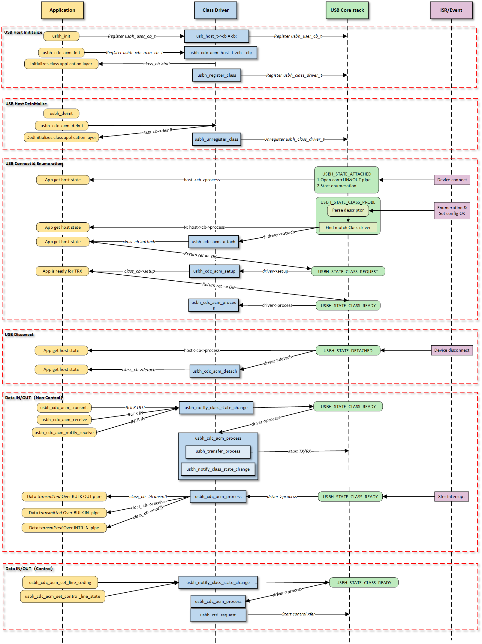
Note
The figure above illustrates the execution flow of callback functions at different levels and does not list all calling scenarios.
Class Driver Callback Functions
The class driver needs to define a standard usbh_class_driver_t structure.
This serves as a unified entry point registered with the USB Core and is the primary method for the Core layer to notify the Class layer that “an event has occurred.”
id_table: Supported device ID list. The core layer uses this table to match with the inserted device to determine whether to load this driver.
attach: Called after device connection and successful matching.
detach: Called when the device is disconnected.
setup: Called when enumeration is complete and the class request phase begins. Used to send class-specific standard control requests to complete necessary configuration before the device enters the data transfer state.
process: The state machine processing function executed after the class driver is ready.
sof: Called during SOF interrupts. Used to handle logic with strict timing requirements, primarily for isochronous transfers.
completed: Called when a transfer on a pipe completes.
Application Layer Callback Functions
The CDC ACM class driver application layer callback structure usbh_cdc_acm_cb_t is implemented by the user layer. Generally, the following APIs can be implemented:
API |
Description |
|---|---|
init |
Called during class driver initialization to initialize application-related resources. |
deinit |
Called during class driver de-initialization to release application-related resources. |
attach |
Called when the class driver executes the attach callback to handle device connection events at the application layer. |
detach |
Called when the class driver executes the detach callback to handle device disconnection events at the application layer. |
setup |
Called when the class driver executes the setup callback, indicating that the application layer class driver is ready for data transfer. |
receive |
Called when the class driver receives BULK IN data, used by the application layer to process data reported by the device. |
transmit |
Called when the class driver BULK OUT data transfer completes, used by the application layer to obtain the OUT transfer status. |
notify |
Called when the class driver receives INTR IN data, used by the application layer to process data reported by the device. |
Loading and Unloading Class Driver
These two functions are responsible for the allocation and release of memory resources, as well as the registration and deregistration of the class driver to the USB core.
usbh_cdc_acm_init() is the top-level function used to load the CDC ACM host class driver. It primarily completes the following tasks:
Saves the user-provided callback functions and calls the user
initcallback.Allocates memory for
line_coding(current device parameters) anduser_line_coding(user expected parameters).Calls
usbh_register_class()to register the CDC ACM class driver with the USB host core.
Example:
int usbh_cdc_acm_init(usbh_cdc_acm_cb_t *cb)
{
    /* 1. Save the user callback and call the user's ``init`` callback */
    if (cb != NULL) {
      cdc->cb = cb;
      if (cb->init != NULL) {
        ret = cb->init();
        if (ret != HAL_OK) {
          RTK_LOGS(TAG, RTK_LOG_ERROR, "User init err %d\n", ret);
          return ret;
        }
      }
    }
    /* 2. Allocate memory */
    cdc->line_coding = (usb_cdc_line_coding_t *)usb_os_malloc(sizeof(usb_cdc_line_coding_t));
    /* ... */

    /* 3. Register class driver*/
    usbh_register_class(&usbh_cdc_acm_driver);
    return ret;
}
usbh_cdc_acm_deinit() is the top-level function used to unload the CDC ACM host class driver, responsible for cleaning up resources:
Calls the user
deinitcallback to inform the application layer.If the device is in a connected state, forcibly closes all open pipes (Interrupt IN, Bulk IN, Bulk OUT).
Frees the previously allocated memory.
Deregisters the class driver.
Example:
int usbh_cdc_acm_deinit(void)
{

  /* 1. Call the user's ``deinit`` callback  */
  if ((cdc->cb != NULL) && (cdc->cb->deinit != NULL)) {
    cdc->cb->deinit();
  }

  /* 2. If the device is connected, forcefully close all open pipes */
  if ((host != NULL) && (host->connect_state == USBH_STATE_SETUP)) {
    usbh_close_pipe(host, &cdc->intr_in);
    /* Close other pipes */
  }

  /* 3. Free memory */
  if (cdc->line_coding != NULL) {
    usb_os_mfree(cdc->line_coding);
  }
  /* ... */

  /* 4. Unregister class driver*/
  usbh_unregister_class(&usbh_cdc_acm_driver);
  return ret;
}
Connection and Disconnection Handling
When the USB core detects the insertion or removal of a device matching the CDC ACM class, the following callback functions are called.
usbh_cdc_acm_attach is a key step in device enumeration, responsible for parsing interface descriptors and allocating pipe resources:
Locate Communication Interface (Comm Interface): If found, parses its interrupt endpoint and opens the Interrupt IN pipe.
Locate Data Interface (Data Interface): If found, parses its bulk endpoints and opens Bulk IN and Bulk OUT pipes.
Initialize the state machine to IDLE state.
Call the user
attachcallback to inform the application layer of the connection status.
Example:
static int usbh_cdc_acm_attach(usb_host_t *host)
{
  /* 1. Get the Communication interface and open the interrupt pipe */
  dev_id.bInterfaceClass = USB_CDC_COMM_INTERFACE_CLASS_CODE;
  itf_data = usbh_get_interface_descriptor(host, &dev_id);
  if (itf_data) {
    usbh_open_pipe(host, intr_in, ep_desc);
  }
  /* 2. Get the Data interface and open the Bulk IN & Bulk OUT pipe */
  dev_id.bInterfaceClass = USB_CDC_DATA_INTERFACE_CLASS_CODE;
  itf_data = usbh_get_interface_descriptor(host, &dev_id);
  /* Open bulk_in / bulk_out pipes */

  /* 3. Initialize the state machine */
  cdc->state = USBH_CDC_ACM_STATE_IDLE;

  /* 4. Notify the user layer */
  if ((cdc->cb != NULL) && (cdc->cb->attach != NULL)) {
      cdc->cb->attach();
  }
  return HAL_OK;
}
usbh_cdc_acm_detach is called when the device is removed. It is responsible for notifying the upper-layer application that the device has been removed and closing all relevant pipes to release hardware channels.
Example:
static int usbh_cdc_acm_detach(usb_host_t *host)
{
  /* 1. Notify the user layer */
  if ((cdc->cb != NULL) && (cdc->cb->detach != NULL)) {
    cdc->cb->detach();
  }
  /* 2. Close pipes */
  if (intr_in->pipe_num) {
    usbh_close_pipe(host, intr_in);
  }
  /* Close bulk_in / bulk_out pipes */
  return HAL_OK;
}
Class Driver State Machine
The usbh_cdc_acm_process callback function is the core state machine handler for the host-side CDC ACM class.
Unlike the passive response mechanism on the device side, the host-side driver must actively maintain the device state.
Its core responsibilities include maintaining the class driver lifecycle states (e.g., IDLE, TRANSFER, ERROR), handling the setting and verification of Line Coding, and distributing data transmission tasks.
State Machine Management and Scheduling
usbh_cdc_acm_process manages the scheduling of control transfers (such as baud rate configuration) and bulk/interrupt data transfers based on the current class driver state.
State Enum |
Description |
Key Actions |
|---|---|---|
IDLE |
Idle state |
Waits for user commands or data transmission requests. |
SET_LINE_CODING |
Send baud rate setting request |
Sends a |
GET_LINE_CODING |
Get/Verify baud rate |
Sends a |
SET_CONTROL_LINE_STATE |
Control handshake signals |
Configures RTS/DTR level states. |
TRANSFER |
Data transferring |
Distributes tasks to specific TX/RX processing functions based on the pipe number. |
ERROR |
Error state |
Attempts to clear endpoint features (Clear Feature) to restore communication. |
Line Coding Configuration (Set & Verify)
The CDC ACM host driver implements a “Set-Readback-Verify” closed-loop process to ensure the device has correctly accepted parameters like the baud rate.
Set: Sends the
SET_LINE_CODINGrequest. Upon success, the state automatically transitions toGET_LINE_CODING.Readback (Get): Sends the
GET_LINE_CODINGrequest to read the current configuration from the device, ensuring serial parameters are synchronized.Verify: Compares the configuration requested by the user with the actual configuration returned by the device. If they match, the configuration is successful. The
line_coding_changedcallback is called to notify the application layer of the successful modification.
Example:
case USBH_CDC_ACM_STATE_SET_LINE_CODING:
  /* 1. Send a setting request */
    req_status = usbh_cdc_acm_process_set_line_coding(host, cdc->user_line_coding);
  if (req_status == HAL_OK) {
    /* 2. After successful setup, immediately goto to get the setting for verification */
    cdc->state = USBH_CDC_ACM_STATE_GET_LINE_CODING;
    }
  /* ... error handling ... */
  break;

  case USBH_CDC_ACM_STATE_GET_LINE_CODING:
    req_status = usbh_cdc_acm_process_get_line_coding(host, cdc->line_coding);
    if (req_status == HAL_OK) {
      cdc->state = USBH_CDC_ACM_STATE_IDLE;
      /* 3. Verify whether the readback data is consistent with the user settings */
      if ((cdc->line_coding->b.dwDteRate == cdc->user_line_coding->b.dwDteRate) &&
      /* ... compare other fields ... */ ) {
        /* 4. Config Match, notify the application layer that the setting has been changed. */
        if ((cdc->cb != NULL) && (cdc->cb->line_coding_changed != NULL)) {
          cdc->cb->line_coding_changed(cdc->line_coding);
        }
    }
  }
  break;
Transfer Processing Distribution
When in the TRANSFER state, processing is distributed to specific TX (transmit), RX (receive), or INTR (interrupt) handler functions based on the pipe number (Pipe ID) that triggered the event.
Example:
case USBH_CDC_ACM_STATE_TRANSFER:
/* Distribute transmission tasks according to pipe numbers */
if (event.msg.pipe_num == cdc->bulk_out.pipe_num) {
  usbh_cdc_acm_process_tx(host);      // Handle BULK OUT transfer
} else if (event.msg.pipe_num == cdc->bulk_in.pipe_num) {
  usbh_cdc_acm_process_rx(host);      // Handle BULK IN transfer
} else if (event.msg.pipe_num == cdc->intr_in.pipe_num) {
  usbh_cdc_acm_process_intr_rx(host); // Handle Interrupt IN transfer(e.g. Serial State)
}
break;
Error Recovery
When an error occurs during other state processing, the driver attempts to clear endpoint features (Clear Feature) and restore to the IDLE state.
Example:
switch (cdc->state) {
/* ... IDLE state ... */

case USBH_CDC_ACM_STATE_ERROR:
  /* Error recovery mechanism */
  req_status = usbh_ctrl_clear_feature(host, 0x00U);
  if (req_status == HAL_OK) {
    cdc->state = USBH_CDC_ACM_STATE_IDLE;
  }
break;
}
Class-Specific Request Processing
Setup Phase Processing
The usbh_cdc_acm_setup callback function is invoked after the basic enumeration is completed.
It initiates the first class-specific request: Get Line Coding, to synchronize the state between the host and the device.
Example:
static int usbh_cdc_acm_setup(usb_host_t *host)
{
    /* Initiate a Get Line Coding request */
    status = usbh_cdc_acm_process_get_line_coding(host, cdc->line_coding);
    return status;
}
APIs for Application
Interfaces provided to the upper-layer application for triggering configuration or data transmission.
Set Control State
usbh_cdc_acm_set_control_line_state(): Switches the state to SET_CONTROL_LINE_STATE and schedules the initiation of the control request within process.
Set/Get Line Coding
usbh_cdc_acm_set_line_coding(): Assembles the Setup packet; the driver switches the state to SET_LINE_CODING and schedules the initiation of the control request within process.usbh_cdc_acm_get_line_coding(): Returns the device parameters read back for verification after the SET_LINE_CODING state.
Data Transfer Processing
The following three APIs for application serve as the interface layer between the USB driver and the application. The driver switches the state to TRANSFER and schedules the distribution of data transmission within the process callback.
CDC ACM Data Interface:
usbh_cdc_acm_transmit(): The application layer passes in data to initiate transmission. It handles Zero Length Packet (ZLP) logic and notifies the application layer of the transmission result via the user transmit callback function.usbh_cdc_acm_receive(): Initiates reception and passes data through to the application layer via the user receive callback function.
CDC ACM Communication Interface:
usbh_cdc_acm_notify_receive(): Initiates interrupt transfer reception and passes data through to the application layer via the user notify callback function.
Transmission Logic and Zero Length Packet (ZLP) Processing
In the bulk data transmission function usbh_cdc_acm_transmit(), the driver must handle the Zero Length Packet (ZLP) issue defined in the USB protocol.
If the length of the transmitted data is exactly an integer multiple of the endpoint’s Maximum Packet Size (MPS), the host must send an additional ZLP to inform the device that the transmission has ended. This is a standard requirement for USB bulk transfers.
Example:
int usbh_cdc_acm_transmit(u8 *buf, u32 len)
{
    usbh_cdc_acm_host_t *cdc = &usbh_cdc_acm_host;
    usb_host_t *host = cdc->host;
    usbh_pipe_t *pipe = &cdc->bulk_out;

    if (pipe->xfer_state == USBH_EP_XFER_IDLE) {
        pipe->xfer_buf = buf;
        pipe->xfer_len = len;

        /* If the data length is greater than 0 and an integer multiple of MPS, a ZLP needs to be sent */
        if ((pipe->xfer_len > 0) && (pipe->xfer_len % pipe->ep_mps) == 0) {
            pipe->trx_zlp = 1;
        } else {
            pipe->trx_zlp = 0;
        }

        cdc->state = USBH_CDC_ACM_STATE_TRANSFER;
        pipe->xfer_state = USBH_EP_XFER_START;
        /* ... notify state change ... */
    }
}
Class-Specific Request Implementation
This driver stack follows the USB CDC ACM specification, encapsulating the implementation and transmission process of core Class-Specific Requests.
Although the specification marks some requests as optional, the host driver implements the following requests to support standard virtual serial port applications.
Developers can refer to the source code path {SDK}/component/usb/host/cdc_acm for extensions.
Class-Specific Request |
Description |
|---|---|
SetLineCoding |
Configures line coding. Sends parameters such as baud rate, stop bits, and parity bits to the device. In pure passthrough mode, this request is mainly used to complete the protocol handshake process. |
GetLineCoding |
Gets line coding. Reads the current line configuration parameters from the device, used to verify if the configuration has taken effect or to synchronize with the device’s default state. |
SetControlLineState |
Sets control signal state. Used to control RTS (Request To Send) and DTR (Data Terminal Ready) signal levels, commonly used for flow control handshakes or to notify the device that the host side is ready. |
Pipe Configuration
The CDC ACM host driver parses the configuration descriptor during the device enumeration phase (usbh_cdc_acm_attach callback function), automatically finding and allocating corresponding transmission resources based on interface subclasses to establish complete data and control channels.
Count |
Description |
|---|---|
2 |
For default control transfer 0. Used for sending standard USB requests and CDC class-specific control requests (e.g., SetLineCoding). |
1 |
For Interrupt IN transfer. Belongs to the Communication Interface (CCI), used to receive notification events (Notify) actively reported by the device. The maximum timeout is set to 1000 ticks. |
1 |
For Bulk IN transfer. Belongs to the Data Interface (DCI), used to receive raw data streams (RX Data) uploaded by the device, supporting large packet transmission and ZLP processing. |
1 |
For Bulk OUT transfer. Belongs to the Data Interface (DCI), used to send raw data streams (TX Data) to the device. The driver layer optimizes DMA scheduling to ensure high-bandwidth transmission. |
API Reference
For detailed function prototypes and usage, please refer to the Driver API
Application Example
Application Design
This section details the complete development process for the CDC ACM Host driver, covering driver initialization, hot-plug management, data transmission and reception mechanisms, and resource release.
Driver Initialization
Before using the CDC ACM Host driver, it is necessary to define the configuration structure and register callback functions, followed by sequentially calling core interfaces to start the USB host controller and the ACM class driver.
Step Description:
Hardware Configuration: Set the USB speed mode (High Speed/Full Speed) and related interrupt priorities.
Callback Registration: Define the
usbh_cdc_acm_cb_tstructure and mount handler functions for each phase (connection, disconnection, data transmission, notification).Core Initialization: Call
usbh_init()to initialize the USB core stack.Class Driver Initialization: Call
usbh_cdc_acm_init()to initialize the CDC ACM class driver.
/* 1. Configure USB speed (High Speed or Full Speed), isr priority and main task priority. */
static usbh_config_t usbh_cfg = {
    .speed = USB_SPEED_HIGH,
    .ext_intr_enable = USBH_SOF_INTR,
    .isr_priority = INT_PRI_MIDDLE,
    //...
};

/* 2. Define USB user-level callbacks. */
static usbh_user_cb_t usbh_usr_cb = {
    .process = cdc_acm_cb_process    /* USB callback to handle class-independent events in the application */
};

/* 3. Define user callbacks for CDC ACM events. */
static usbh_cdc_acm_cb_t cdc_acm_usr_cb = {
    .init   = cdc_acm_cb_init,        /* Class init callback */
    .deinit = cdc_acm_cb_deinit,      /* Class deinit callback */
    .attach = cdc_acm_cb_attach,      /* Device attach callback */
    .detach = cdc_acm_cb_detach,      /* Device detach callback */
    .setup  = cdc_acm_cb_setup,       /* Class setup callback */
    .transmit = cdc_acm_cb_transmit,  /* Data transmit callback */
    .receive  = cdc_acm_cb_receive,   /* Data receive callback */
    .notify   = cdc_acm_cb_notify,    /* Interrupt notify callback */
};

int status = 0;

/*4. Initialize USB host core driver with configuration. */
status = usbh_init(&usbh_cfg, &usbh_usr_cb);
if (status != HAL_OK) {
   return;
}

/* 5. Initialize CDC ACM class driver.  */
status = usbh_cdc_acm_init(&cdc_acm_usr_cb);
if (status != HAL_OK) {
    /* If class driver init fails, clean up the core driver */
    usbh_deinit();
    return;
}
Hot-Plug Event Handling
Monitor the connection and disconnection of CDC ACM devices by registering the attach and detach callback functions in usbh_cdc_acm_cb_t.
In the example code, semaphore mechanisms are used to synchronize states:
Attach: When a device is inserted and enumerated successfully, the
attachcallback is triggered, releasing thecdc_acm_attach_semato notify the main thread to start data testing.Detach: When a device is removed, the
detachcallback is triggered, releasing thecdc_acm_detach_semato trigger the hot-plug management thread for resource cleanup and re-initialization.
/* 1. Configure USB status change callback */
static usbd_cdc_acm_cb_t cdc_acm_cb = {
    .status_changed = cdc_acm_cb_status_changed
};

/* 2. Configure Callback executed in ISR context */
static void cdc_acm_cb_status_changed(u8 old_status, u8 status)
{
    RTK_LOGS(TAG, RTK_LOG_INFO, "Status change: %d -> %d \n", old_status, status);

    cdc_acm_attach_status = status;
    rtos_sema_give(cdc_acm_attach_status_changed_sema);
}

/* 3. Create thread handling the state machine */
static void cdc_acm_hotplug_thread(void *param)
{
    int ret = 0;
    UNUSED(param);

    for (;;) {
        if (rtos_sema_take(cdc_acm_attach_status_changed_sema, RTOS_SEMA_MAX_COUNT) == RTK_SUCCESS) {
            if (cdc_acm_attach_status == USBD_ATTACH_STATUS_DETACHED) {
                RTK_LOGS(TAG, RTK_LOG_INFO, "DETACHED\n");

                /* 1.Clean up resources */
                usbd_cdc_acm_deinit();
                ret = usbd_deinit();
                if (ret != 0) {
                    break;
                }

                /* 2.Re-initialize for next connection */
                ret = usbd_init(&cdc_acm_cfg);
                if (ret != 0) {
                    break;
                }
                ret = usbd_cdc_acm_init(CONFIG_CDC_ACM_BULK_OUT_XFER_SIZE, CONFIG_CDC_ACM_BULK_IN_XFER_SIZE, &cdc_acm_cb);
                if (ret != 0) {
                    usbd_deinit();
                    break;
                }
            } else if (cdc_acm_attach_status == USBD_ATTACH_STATUS_ATTACHED) {
                RTK_LOGS(TAG, RTK_LOG_INFO, "ATTACHED\n");
            } else {
                RTK_LOGS(TAG, RTK_LOG_INFO, "INIT\n");
            }
        }
    }
    RTK_LOGS(TAG, RTK_LOG_INFO, "Hotplug thread fail\n");
    rtos_task_delete(NULL);
}
Data Transfer Processing
Once the CDC ACM device is successfully enumerated, the host can perform control transfers, data transfers, and interrupt notification reception.
Control Request
The host uses
usbh_cdc_acm_get_line_coding()andusbh_cdc_acm_set_line_coding()to get or set serial parameters such as baud rate and stop bits.Example: Set the baud rate to 38400 and perform readback verification.
static void cdc_acm_request_test(void)
{
    int ret;
    usbh_cdc_acm_line_coding_t line_coding;
    usbh_cdc_acm_line_coding_t new_line_coding;

    /* Wait for device attach */
    ......

    /* 1. Get current line coding from device */
    ret = usbh_cdc_acm_get_line_coding(&line_coding);
    if (ret != HAL_OK) {
        /* Get failed */
    }

    /* 2. Modify configuration parameters */
    /* Baudrate: 38400, Stop bits: 1, Parity: None, Data bits: 8*/
    line_coding.b.dwDteRate = 38400;
    line_coding.b.bCharFormat = CDC_ACM_LINE_CODING_CHAR_FORMAT_1_STOP_BITS;
    line_coding.b.bParityType = CDC_ACM_LINE_CODING_PARITY_NO;
    line_coding.b.bDataBits = 8;

    /* 3. Set new line coding to device */
    ret = usbh_cdc_acm_set_line_coding(&line_coding);
    if (ret != HAL_OK) {
        /* Set failed */
    }

    /* Wait for the setting to take effect */
    rtos_time_delay_ms(10);

    /* 4. Get line coding again to verify */
    ret = usbh_cdc_acm_get_line_coding(&new_line_coding);

    /* 5. Compare set values with read-back values */
    ......
}
Bulk Transfer
The driver uses an asynchronous transmission mechanism, combined with semaphores to implement synchronization logic:
Send: Call
usbh_cdc_acm_transmit()to send data. Upon completion, the driver calls back thetransmitfunction and releasescdc_acm_send_sema.Receive: Call
usbh_cdc_acm_receive()to prepare to receive data. Upon receiving data, the driver calls back thereceivefunction and releasescdc_acm_receive_sema.
/* RX Callback: Handle Reception Completion */
static int cdc_acm_cb_receive(u8 *buf, u32 len, u8 status)
{
    if (status == HAL_OK) {
    u16 cdc_acm_bulk_in_mps = usbh_cdc_acm_get_bulk_ep_mps();

    /* 1. Copy data to internal buffer (Logic for buffer overflow check included) */
    if ((len > 0) && ((cdc_acm_total_rx_len + len) <= USBH_CDC_ACM_LOOPBACK_BUF_SIZE)) {
        /* memcpy(cdc_acm_loopback_rx_buf + cdc_acm_total_rx_len, buf, len); */
    }
    cdc_acm_total_rx_len += len;

    /* 2. Check for ZLP, short packet, or buffer full to complete the transfer */
    if ((len == 0) || (len % cdc_acm_bulk_in_mps)
        || ((len % cdc_acm_bulk_in_mps == 0) && (len < USBH_CDC_ACM_LOOPBACK_BUF_SIZE))
        || (cdc_acm_total_rx_len > USBH_CDC_ACM_LOOPBACK_BUF_SIZE)) {

        cdc_acm_total_rx_len = 0;

        /* 3. Signal the receive semaphore */
        rtos_sema_give(cdc_acm_receive_sema);
    }
    } else {
        RTK_LOGS(TAG, RTK_LOG_ERROR, "RX fail: %d\n", status);
    }
    return HAL_OK;
}

/* TX Callback: Handle Transmission Completion */
static int cdc_acm_cb_transmit(u8 status)
{
    if (status == HAL_OK) {
        /* TX done, signal semaphore */
        rtos_sema_give(cdc_acm_send_sema);
    } else {
        RTK_LOGS(TAG, RTK_LOG_ERROR, "TX fail: %d\n", status);
    }

    return HAL_OK;
}

/* Task thread: Handle Loopback Test Logic */
static void cdc_acm_loopback_test(void)
{
    int i;
    int ret;

    /* Initialize TX buffer */
    //...

    for (i = 0; i < USBH_CDC_ACM_LOOPBACK_CNT; i++) {

        /* Prepare RX buffer and check device status */
        //...

        /* 1. Transmit Data */
        ret = usbh_cdc_acm_transmit(cdc_acm_loopback_tx_buf, USBH_CDC_ACM_LOOPBACK_BUF_SIZE);
        if (ret < 0) {
            RTK_LOGS(TAG, RTK_LOG_ERROR, "TX fail: %d\n", ret);
            return;
        }

        /* 2. Wait for TX Complete signal */
        if (rtos_sema_take(cdc_acm_send_sema, RTOS_SEMA_MAX_COUNT) == RTK_SUCCESS) {
            /* 3. Prepare to Receive Data */
            usbh_cdc_acm_receive(cdc_acm_loopback_rx_buf, USBH_CDC_ACM_LOOPBACK_BUF_SIZE);
        }

        /* 4. Wait for RX Complete signal and Verify Data */
        if (rtos_sema_take(cdc_acm_receive_sema, RTOS_SEMA_MAX_COUNT) == RTK_SUCCESS) {
            /* Check rx data integrity */
            //...
        }
    }
    RTK_LOGS(TAG, RTK_LOG_INFO, "Bulk loopback test PASS\n");
}
Interrupt Notify
Use
usbh_cdc_acm_notify_receive()to listen for interrupt transfers from the device (such as Serial State changes). When a notification is received, thenotifycallback is triggered.
/* Callback: Handle Interrupt Notify */
static int cdc_acm_cb_notify(u8 *buf, u32 len, u8 status)
{
    /* Handle buf and len */
    //...

    if (status == HAL_OK) {
        /* Notify received, signal semaphore to notify the task */
        rtos_sema_give(cdc_acm_notify_sema);
    } else {
        RTK_LOGS(TAG, RTK_LOG_ERROR, "Notify fail: %d\n", status);
    }
    return HAL_OK;
}

/* Task Thread: Execute Notify Test Logic */
static void cdc_acm_notify_test_thread(void *param)
{
    /* Wait for device ready */
    //...

    /* 1. Optional: Change control line state to trigger device notification */
    usbh_cdc_acm_set_control_line_state();

    rtos_time_delay_ms(2000);

    for (int i = 0; i < USBH_CDC_ACM_LOOPBACK_CNT; i++) {
        /* 2. Submit Interrupt IN Request to listen for notification */
        usbh_cdc_acm_notify_receive(cdc_acm_notify_rx_buf, USBH_CDC_ACM_NOTIFY_BUF_SIZE);

        /* 3. Wait for Notify Callback */
        if (rtos_sema_take(cdc_acm_notify_sema, RTOS_SEMA_MAX_COUNT) == RTK_SUCCESS) {
            /* Notification received. Check data (e.g. Serial State at offset 8) */
            RTK_LOGS(TAG, RTK_LOG_INFO, "Intr rx success(0x%02x 0x%02x)\n",
                cdc_acm_notify_rx_buf[9], cdc_acm_notify_rx_buf[8]);
        }
    }
    RTK_LOGS(TAG, RTK_LOG_INFO, "Intr notify test PASS\n");
    rtos_task_delete(NULL);
}
Note
For complete data testing logic, please refer to the SDK example code: {SDK}/example/usb/usbh_cdc_acm/example_usbh_cdc_acm.c.
Driver Deinitialization
When the device is disconnected or the USB host function needs to be disabled, the class driver and the host core driver must be unloaded in sequence, and related system resources must be released.
/* 1. Deinitialize CDC ACM class driver. */
usbh_cdc_acm_deinit();

/* 2. Deinitialize USB host core driver */
usbh_deinit();
Operation method
This section introduces a complete USB CDC ACM Host example, demonstrating how Ameba, acting as a host, identifies a CDC device and performs baud rate setting, data loopback testing, and interrupt notification testing.
The example code path: {SDK}/example/usb/usbh_cdc_acm.
Configuration and Compilation
Compilation and Flashing
Execute the following commands in the SDK root directory to configure the environment, select the target SoC, compile the project, and flash the generated
Imagefile to the development board:# Initialize environment (required for every new terminal) source env.sh or env.bat(Windows system) # Select Target SoC (replace xxx with your specific SoCs) ameba.py soc xxx ameba.py build -a usbh_cdc_acm -p
Confirmation of Menuconfig configuration
If compilation fails, please execute
ameba.py menuconfigand confirm thatUSBH CDC ACMhas been selected.- Choose `CONFIG USB --->`: [*] Enable USB USB Mode (Host) ---> [*] CDC ACM
Result Verification
Start Host
Restart the development board and observe the serial log; the following startup information should be displayed:
[ACM-I] USBD CDC ACM demo start
Connect Device
Use a USB cable to connect a specific USB CDC ACM device (e.g., another Ameba board running the
usbd_cdc_acmexample code) to the USB port of this development board.Serial Communication Test
If the operation is normal after connection, the control transmission test and bulk transmission loopback test will be conducted in sequence. The serial port log will display the following success message:
```
[ACM-I] Ctrl test PASS
[ACM-I] Bulk loopback test start, loopback times:100, size: 1024
[ACM-I] Bulk loopback test PASS
```
