This chapter describes the default Flash memory layout and customization methods.
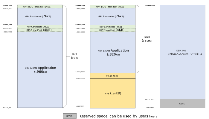
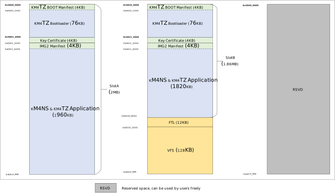
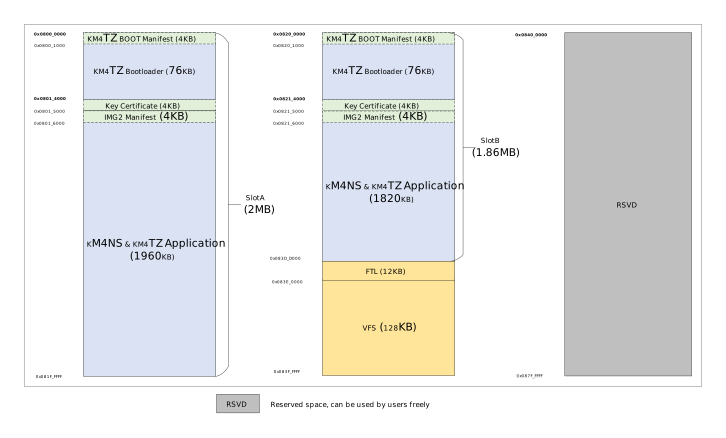
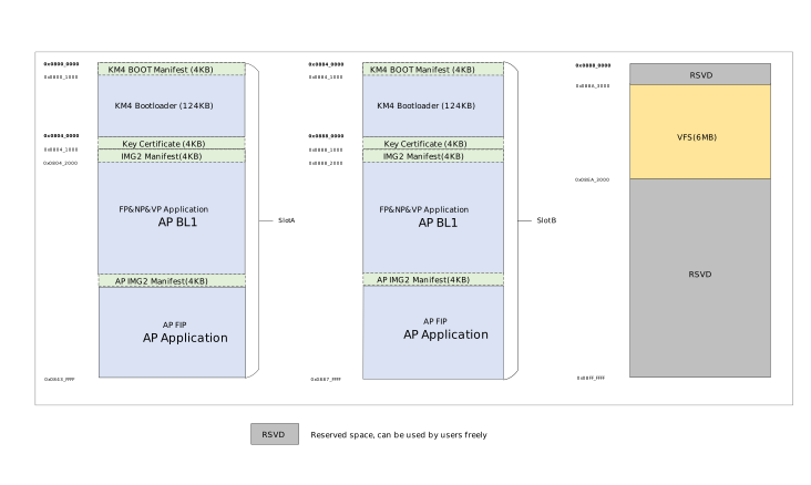
The SDK adopts the default Flash layout shown below (using an 8MB Flash chip as an example). The boot manifest start address is fixed at 0x0800_0000, while other regions support flexible address configuration.
RTL8721Dx:
Item
Physical address
Size (KB)
Description
KM4 Bootloader manifest
0x0800_0000
4
KM4 bootloader manifest
KM4 Bootloader
0x0800_1000
76
KM4 bootloader (code/data), containing KM4 bootloader IMG, mapped to the virtual address 0x0F80_0000.
Key Certificate
0x0801_4000
4
Public key hash information for other images.
IMG2 manifest
0x0801_5000
4
KM0 & KM4 Application & KM4 IMG3 manifest
KM0 & KM4 Application
0x0801_6000
1960
Combines KM0 image, KM4 image2 and KM4 image3 (if exists)
KM0_IMG: KM0 image (code/data), mapped to the virtual address 0x0C00_0000.
KM4_IMG2: KM4 non-secure image (code/data), mapped to the virtual address 0x0E00_0000.
KM4_IMG3: secure image (code/data)
KM4 Bootloader manifest OTA2
0x0820_0000
4
KM4 bootloader manifest
KM4 Bootloader OTA2
0x0820_1000
76
KM4 bootloader (code/data), containing KM4 bootloader IMG, mapped to the virtual address 0x0F80_0000.
Key Certificate OTA2
0x0821_4000
4
Public key hash information for other images.
IMG2 manifest OTA2
0x0821_5000
4
KM0 & KM4 Application & KM4 IMG3 manifest
KM0 & KM4 Application OTA2
0x0821_6000
1820
Combines KM0 image, KM4 image2 and KM4 image3 (if exists)
KM0_IMG: KM0 image (code/data), mapped to the virtual address 0x0C00_0000.
KM4_IMG2: KM4 non-secure image (code/data), mapped to the virtual address 0x0E00_0000.
KM4_IMG3: secure image (code/data)
FTL
0x083D_D000
12
For Bluetooth
VFS
0x083E_0000
128
For file system
RTL8720E:
Item
Physical address
Size
Description
KM4 Bootloader manifest
0x0800_0000
4KB
KM4 bootloader manifest
KM4 Bootloader
0x0800_1000
76KB
KM4 bootloader (code/data), containing KM4 bootloader IMG, mapped to the virtual address 0x0F80_0000.
Key Certificate
0x0801_4000
4KB
Public key hash information for other images.
IMG2 manifest
0x0801_5000
4KB
KR4 & KM4 Application manifest
KR4 & KM4 Application
0x0801_6000
1912KB
Combines KR4 image, KM4 image2 and KM4 image3 (if exists)
KR4_IMG: KR4 image (code/data), mapped to the virtual address 0x0C00_0000.
KM4_IMG2: KM4 non-secure image (code/data), mapped to the virtual address 0x0E00_0000.
To achieve firmware flexibility and meet RSIP encryption requirements (firmware encryption requires fixed IV address, see
RSIP
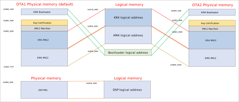
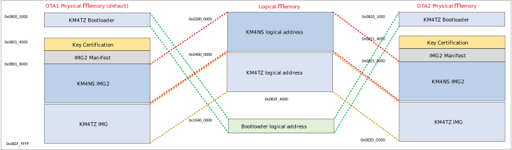
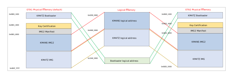
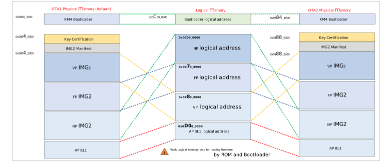
), the SDK enables Flash MMU mechanism by default. Through MMU, the same logical address can be mapped to either OTA1 physical region or OTA2 physical region, enabling devices to select firmware from different partitions. When OTA updates are not enabled, firmware is programmed to OTA1 region by default. For more information about OTA, refer to
OTA
.
Default MMU layout:
RTL8721Dx:
RTL8720E:
RTL8710E:
RTL8726E:
RTL8713E:
RTL8730E:
RTL8721F:
RTL8720F:
RTL8735C:
Note
Generally, Flash logical addresses should not be modified. Contact Realtek for customization needs.
Adjust Flash layout by configuring partition offsets and sizes through Menuconfig. All partitions except IMG_BOOT can be customized. The IMG_BOOT start address is fixed at 0x0800_0000.
To modify the Flash layout:
Run ameba.pymenuconfig.
Navigate to CONFIG User Config > Flash Layout Configuration.
Configure the offset and size for each partition as needed.
Save and exit menuconfig.
Re-build the project.
Note
Actual ICs may not include all partition entries. Refer to IC-specific flash layout for available partitions.
When modifying VFS/FTL partitions, use ImageTool to erase related regions to prevent data conflicts.
Ensure no overlap between adjacent partitions. An overlap check is performed automatically when exiting menuconfig.
Both BOOT and APP firmware have two partitions (OTA1/OTA2) for redundancy and version control. BOOT OTA is disabled by default - enable it via
BOOT OTA
.
To modify the Bootloader OTA2 partition, set BOOTOTA2Offset and BOOTOTA2Size in CONFIG User Config > Flash Layout Configuration of menuconfig. Ensure the offset is 4K-aligned.
Note
Bootloader OTA1 address is fixed at 0x0800_0000 and cannot be modified.
ROM bootloader selects partitions based on version numbers in firmware headers. Higher version gets priority. See
Image Pattern and Version Number
.
In menuconfig, navigate to CONFIG User Config > Flash Layout Configuration and set APPOTA1Offset and APPOTA1Size.
Re-build the project to generate the bootloader and APP OTA1.
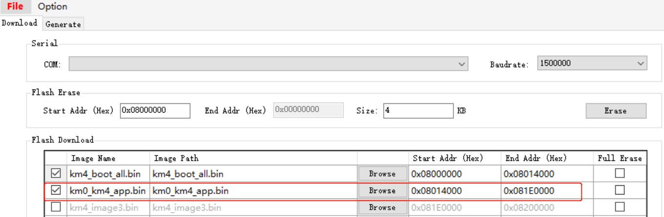
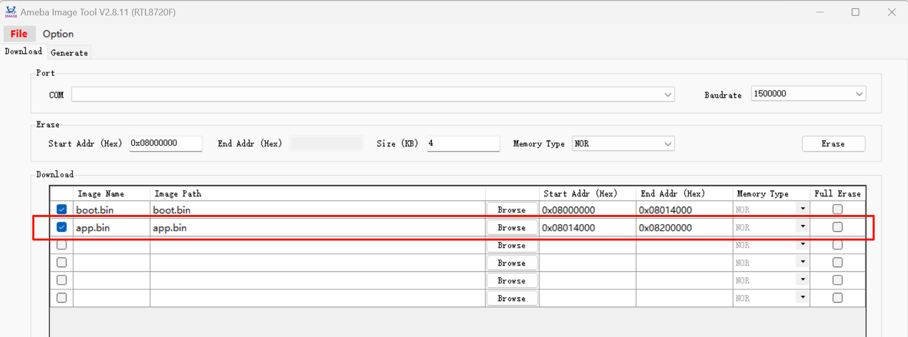
Modify the address of app.bin through ImageTool, and download the new bootloader and APP OTA1.
After that, the bootloader will load the image from the new location of APP OTA1 if the version of APP OTA1 is bigger.
APP OTA2
In menuconfig, navigate to CONFIG User Config > Flash Layout Configuration and set APPOTA2Offset and APPOTA2Size.
Re-build and download the new bootloader and APP OTA2 as described in Section
APP OTA1
.
After burning the APP OTA2 into Flash through OTA, bootloader will load the image from the new location of APP OTA2 if the version of APP OTA2 is bigger.
RTL8720E:
APP OTA1
In menuconfig, navigate to CONFIG User Config > Flash Layout Configuration and set APPOTA1Offset and APPOTA1Size.
Re-build the project to generate the bootloader and APP OTA1.
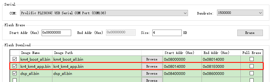
Modify the address of app.bin through ImageTool, and download the new bootloader and APP OTA1.
The bootloader will load the image from the new APP OTA1 location only if the version of APP OTA1 is higher.
APP OTA2
In menuconfig, navigate to CONFIG User Config > Flash Layout Configuration and set APPOTA2Offset and APPOTA2Size.
Re-build and download the new bootloader and APP OTA2 as described in Section
APP OTA1
.
After burning APP OTA2 via OTA, the bootloader will load the image from the new APP OTA2 location only if its version is higher.
RTL8710E:
APP OTA1
In menuconfig, navigate to CONFIG User Config > Flash Layout Configuration and set APPOTA1Offset and APPOTA1Size.
Re-build the project to generate the bootloader and APP OTA1.
Modify the address of app.bin through ImageTool, and download the new bootloader and APP OTA1.
The bootloader will load the image from the new APP OTA1 location only if the version of APP OTA1 is higher.
APP OTA2
In menuconfig, navigate to CONFIG User Config > Flash Layout Configuration and set APPOTA2Offset and APPOTA2Size.
Re-build and download the new bootloader and APP OTA2 as described in Section
APP OTA1
.
After burning APP OTA2 via OTA, the bootloader will load the image from the new APP OTA2 location only if its version is higher.
RTL8726E:
APP OTA1
In menuconfig, navigate to CONFIG User Config > Flash Layout Configuration and set APPOTA1Offset and APPOTA1Size.
Re-build the project to generate the bootloader and APP OTA1.
Modify the address of app.bin through ImageTool, and download the new bootloader and APP OTA1.
The bootloader will load the image from the new APP OTA1 location only if the version of APP OTA1 is higher.
APP OTA2
In menuconfig, navigate to CONFIG User Config > Flash Layout Configuration and set APPOTA2Offset and APPOTA2Size.
Re-build and download the new bootloader and APP OTA2 as described in Section APP OTA1.
After burning APP OTA2 via OTA, the bootloader will load the image from the new APP OTA2 location only if its version is higher.
Modifying DSP IMG Location
In menuconfig, navigate to CONFIG User Config > Flash Layout Configuration and set DSPOffset and DSPSize (visible only when DSP is enabled).
RTL8713E:
APP OTA1
In menuconfig, navigate to CONFIG User Config > Flash Layout Configuration and set APPOTA1Offset and APPOTA1Size.
Re-build the project to generate the bootloader and APP OTA1.
Modify the address of app.bin through ImageTool, and download the new bootloader and APP OTA1.
The bootloader will load the image from the new APP OTA1 location only if the version of APP OTA1 is higher.
APP OTA2
In menuconfig, navigate to CONFIG User Config > Flash Layout Configuration and set APPOTA2Offset and APPOTA2Size.
Re-build and download the new bootloader and APP OTA2 as described in Section APP OTA1.
After burning APP OTA2 via OTA, the bootloader will load the image from the new APP OTA2 location only if its version is higher.
Modifying DSP IMG Location
In menuconfig, navigate to CONFIG User Config > Flash Layout Configuration and set DSPOffset and DSPSize (visible only when DSP is enabled).
RTL8730E:
APP OTA1
In menuconfig, navigate to CONFIG User Config > Flash Layout Configuration and set APPOTA1Offset and APPOTA1Size.
Recompile the project to generate Bootloader and APP OTA1
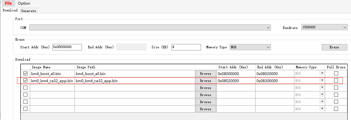
The start/end addresses of IMG_APP_OTA1 correspond to Start Addr and End Addr in ImageTool`` for app.bin, indicating firmware programming location. If IMG_APP_OTA1 is modified, update corresponding ImageTool settings and download new Bootloader & APP OTA1.
Bootloader selects partitions based on version numbers in firmware headers. If APP OTA1 has a higher version number, Bootloader will load firmware from the new APP OTA1 location.
APP OTA2
In menuconfig, navigate to CONFIG User Config > Flash Layout Configuration and set APPOTA2Offset and APPOTA2Size.
Follow steps in
APP OTA1
to recompile and download Bootloader firmware
After OTA updates program APP OTA2 to Flash, Bootloader will load from the new APP OTA2 location if it has a higher version number.
RTL8721F:
APP OTA1
In menuconfig, navigate to CONFIG User Config > Flash Layout Configuration and set APPOTA1Offset and APPOTA1Size.
Recompile the project to generate Bootloader and APP OTA1.
The start and end addresses of IMG_APP_OTA1 correspond to the Start Addr and End Addr in ImageTool for app.bin, indicating the application firmware programming location. If IMG_APP_OTA1 is modified, update the corresponding items in ImageTool and download the new Bootloader and APP OTA1.
Bootloader selects which partition to boot based on tags and version numbers in the APP firmware header. If APP OTA1 has a higher version number, the Bootloader loads firmware from the new APP OTA1 location.
APP OTA2
In menuconfig, navigate to CONFIG User Config > Flash Layout Configuration and set APPOTA2Offset and APPOTA2Size.
Follow the steps in
APP OTA1
to recompile and download Bootloader firmware.
After APP OTA2 is downloaded to Flash via OTA, if APP OTA2 has a higher version number, the Bootloader will load firmware from the new APP OTA2 location.
RTL8720F:
APP OTA1
In menuconfig, navigate to CONFIG User Config > Flash Layout Configuration and set APPOTA1Offset and APPOTA1Size.
Recompile the project to generate Bootloader and APP OTA1.
The start and end addresses of IMG_APP_OTA1 correspond to the Start Addr and End Addr in ImageTool for app.bin, indicating the application firmware programming location. If IMG_APP_OTA1 is modified, update the corresponding items in ImageTool and download the new Bootloader and APP OTA1.
Bootloader selects which partition to boot based on tags and version numbers in the APP firmware header. If APP OTA1 has a higher version number, the Bootloader loads firmware from the new APP OTA1 location.
APP OTA2
In menuconfig, navigate to CONFIG User Config > Flash Layout Configuration and set APPOTA2Offset and APPOTA2Size.
Follow the steps in
APP OTA1
to recompile and download Bootloader firmware.
After APP OTA2 is downloaded to Flash via OTA, if APP OTA2 has a higher version number, the Bootloader will load firmware from the new APP OTA2 location.
RTL8735C:
APP OTA1
Modify IMG_APP_OTA1 addresses in {SDK}\component\soc\amebaxxx\usrcfg\ameba_flashcfg.c
Recompile the project to generate Bootloader and APP OTA1
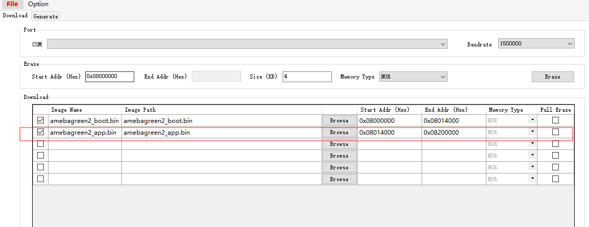
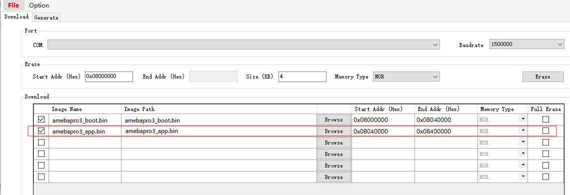
The start/end addresses of IMG_APP_OTA1 correspond to Start Addr and End Addr in ImageTool for amebapro3_app.bin, indicating firmware programming location. If IMG_APP_OTA1 is modified, update corresponding ImageTool settings and download new Bootloader & APP OTA1.
Bootloader selects partitions based on version numbers in firmware headers. If APP OTA1 has a higher version number, Bootloader will load firmware from the new APP OTA1 location.
APP OTA2
Modify IMG_APP_OTA2 addresses in {SDK}\component\soc\amebaxxx\usrcfg\ameba_flashcfg.c
Follow steps in
APP OTA1
to recompile and download Bootloader firmware
After OTA updates program APP OTA2 to Flash, Bootloader will load from the new APP OTA2 location if it has a higher version number.
Before loading APP images, the bootloader checks the Flash status register:
If bitwise AND result with status_mask in Flash_AVL (path: {SDK}\component\soc\usrcfg\amebaxxx\ameba_flashcfg.c) sets only QE bit, retain current status
Otherwise write the result to the status register
/*** @brief Flash_AVL maintains the flash IC supported by SDK.* If users want to adopt new flash, add item in the following AVL.* Note that, if new flash can be classified as one of the Realtek-defined categories according to Classification SPEC,* filling in the defined class index is necessary. Otherwise, FlashClassUser can be used to indicate new class.* If (Status Register of flash & status_mask in Flash_AVL) != (1 << QE Bit), set (1 << QE Bit) to Status Register of flash*/constFlashInfo_TypeDefFlash_AVL[]={/*flash_id, flash_id_mask, flash_class, status_mask, FlashInitHandler *//* case1: Realtek defined class, any modification is not allowed */{0xEF,0x000000FF,FlashClass1,0x000043FC,NULL},/* Winbond: MANUFACTURER_ID_WINBOND */{0xA1,0x000000FF,FlashClass1,0x0000FFFC,NULL},/* Fudan Micro: MANUFACTURER_ID_FM */{0x0B,0x000000FF,FlashClass1,0x000043FC,NULL},/* XTX */{0x0E,0x000000FF,FlashClass1,0x000043FC,NULL},/* XTX(FT) */{0xC8,0x000000FF,FlashClass2,0x000043FC,NULL},/* GD normal: MANUFACTURER_ID_GD */{0x28C2,0x0000FFFF,FlashClass6,0x000200FC,NULL},/* MXIC wide-range VCC: MANUFACTURER_ID_MXIC */{0xC2,0x000000FF,FlashClass3,0x000000FC,NULL},/* MXIC normal: MANUFACTURER_ID_BOHONG */{0x68,0x000000FF,FlashClass3,0x000000FC,NULL},/* Hua Hong */{0x51,0x000000FF,FlashClass3,0x000000FC,NULL},/* GD MD serial */{0x1C,0x000000FF,FlashClass4,0x000000FC,NULL},/* ESMT: MANUFACTURER_ID_EON */{0x20,0x000000FF,FlashClass1,0x000043FC,NULL},/* XMC: MANUFACTURER_ID_WINBOND */{0x85,0x000000FF,FlashClass1,0x000043FC,NULL},/* Puya: 85-20-16 */{0x5E,0x000000FF,FlashClass1,0x000043FC,NULL},/* Zbit: 5E-50-16 *///{0x20, 0x000000FF, FlashClass5, 0x000000FC, NULL}, /* Micron: MANUFACTURER_ID_MICRON *//* case2: new flash, ID is not included in case1 list, but specification is compatible with FlashClass1~FlashClass6 *///{0xXX, 0x0000XXXX, FlashClassX, 0x0000XXXX, NULL},/* case3: new flash, ID is not included in case1 list, and specification is not compatible with FlashClass1~FlashClass6 */{0x00,0x000000FF,FlashClassUser,0xFFFFFFFF,&flash_init_userdef},/* End */{0xFF,0xFFFFFFFF,FlashClassNone,0xFFFFFFFF,NULL},};
Note
Default QE setting disables all block protection. To preserve protection, clear corresponding bits in status_mask (e.g., set Winbond’s mask to 0x000043C0)
Recommended to enable block protection for code segments and read-only data.
When using LittleFS, recommend placing FTL partition in the last 64KB region with block protection
Disable protection during OTA updates and re-enable afterward
For Flashes that cannot protect only the last block, enable protection for the first half region