Overview
The OTPC is an embedded non-volatile memory based on Anti-fuse technology, featuring a high level of hardware security. Its core characteristic is data immutability: the default initial state of the physical region is 1, which supports only a one-time, irreversible programming to 0.
The logical zone serves as a virtual extension of the physical zone. Through specific mapping algorithms, the “write-once” characteristic of the physical zone is transformed into a “multi-time modifiable” functionality for the logical zone, allowing users to update configuration information multiple times within certain limits.
OTP Layout
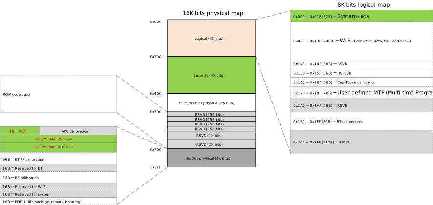
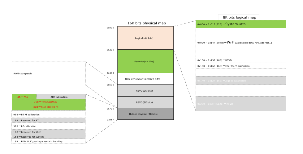
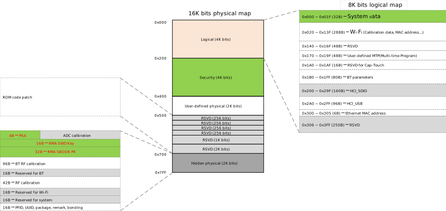
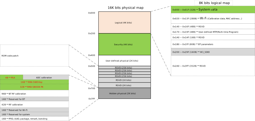
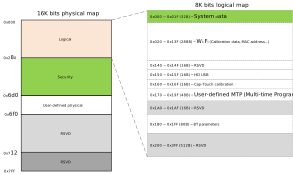
The OTP layout is shown in the figure below.

Note
Refer to the corresponding User Manual for the detailed layout of each OTP partition.
Physical Zone
The size of the physical zone is 0x800 bytes. Its layout has been predefined by Realtek and includes the mapping zone, security zone, user-defined physical zone, ROM code patch zone, and hidden physical zone.
Caution
The physical zone only supports a one-time, irreversible write from 1 to 0. Please operate with caution.
Physical Zone Partition |
Address |
Description |
Usage |
|---|---|---|---|
Mapping Zone |
(0x000-0x1FF, 512 bytes) |
Mapped to the logical zone |
- |
Security Zone |
(0x200-0x37F, 384 bytes) |
Stores various keys and related configurations |
|
User-defined Physical Zone |
(0x380-0x4FF, 384 bytes) |
For user’s free use |
|
ROM Code Patch Zone |
(0x500-0x6FF, 512 bytes) |
Used for applying patches to ROM code |
|
Hidden Physical Zone |
(0x700-0x7FF, 256 bytes) |
Used for functions like RMA |
Physical Zone Partition |
Address |
Description |
Usage |
|---|---|---|---|
Mapping Zone |
(0x000-0x1FF, 512 bytes) |
Mapped to the logical zone |
- |
Security Zone |
(0x200-0x37F, 384 bytes) |
Stores various keys and related configurations |
|
User-defined Physical Zone |
(0x380-0x4FF, 384 bytes) |
For user’s free use |
|
ROM Code Patch Zone |
(0x500-0x6FF, 512 bytes) |
Used for applying patches to ROM code |
|
Hidden Physical Zone |
(0x700-0x7FF, 256 bytes) |
Used for functions like RMA |
Physical Zone Partition |
Address |
Description |
Usage |
|---|---|---|---|
Mapping Zone |
(0x000-0x1FF, 512 bytes) |
Mapped to the logical zone |
- |
Security Zone |
(0x200-0x37F, 384 bytes) |
Stores various keys and related configurations |
|
User-defined Physical Zone |
(0x380-0x4FF, 384 bytes) |
For user’s free use |
|
ROM Code Patch Zone |
(0x500-0x6FF, 512 bytes) |
Used for applying patches to ROM code |
|
Hidden Physical Zone |
(0x700-0x7FF, 256 bytes) |
Used for functions like RMA |
Physical Zone Partition |
Address |
Description |
Usage |
|---|---|---|---|
Mapping Zone |
(0x000-0x1FF, 512 bytes) |
Mapped to the logical zone |
- |
Security Zone |
(0x200-0x37F, 384 bytes) |
Stores various keys and related configurations |
|
User-defined Physical Zone |
(0x380-0x4FF, 384 bytes) |
For user’s free use |
|
ROM Code Patch Zone |
(0x500-0x6FF, 512 bytes) |
Used for applying patches to ROM code |
|
Hidden Physical Zone |
(0x700-0x7FF, 256 bytes) |
Used for functions like RMA |
Physical Zone Partition |
Address |
Description |
Usage |
|---|---|---|---|
Mapping Zone |
(0x000-0x1FF, 512 bytes) |
Mapped to the logical zone |
- |
Security Zone |
(0x200-0x37F, 384 bytes) |
Stores various keys and related configurations |
|
User-defined Physical Zone |
(0x380-0x4FF, 384 bytes) |
For user’s free use |
|
ROM Code Patch Zone |
(0x500-0x6FF, 512 bytes) |
Used for applying patches to ROM code |
|
Hidden Physical Zone |
(0x700-0x7FF, 256 bytes) |
Used for functions like RMA |
Physical Zone Partition |
Address |
Description |
Usage |
|---|---|---|---|
Mapping Zone |
(0x000-0x1FF, 512 bytes) |
Mapped to the logical zone |
- |
Security Zone |
(0x200-0x37F, 384 bytes) |
Stores various keys and related configurations |
|
User-defined Physical Zone |
(0x380-0x4FF, 384 bytes) |
For user’s free use |
|
ROM Code Patch Zone |
(0x500-0x6FF, 512 bytes) |
Used for applying patches to ROM code |
|
Hidden Physical Zone |
(0x700-0x7FF, 256 bytes) |
Used for functions like RMA |
Physical Zone Partition |
Address |
Description |
Usage |
|---|---|---|---|
Mapping Zone |
(0x000-0x1FF, 512 bytes) |
Mapped to the logical zone |
- |
Security Zone |
(0x200-0x37F, 384 bytes) |
Stores various keys and related configurations |
|
User-defined Physical Zone |
(0x380-0x4FF, 384 bytes) |
For user’s free use |
|
ROM Code Patch Zone |
(0x500-0x6FF, 512 bytes) |
Used for applying patches to ROM code |
|
Hidden Physical Zone |
(0x700-0x7FF, 256 bytes) |
Used for functions like RMA |
Physical Zone Partition |
Address |
Description |
Usage |
|---|---|---|---|
Mapping Zone |
(0x000-0x1FF, 512 bytes) |
Mapped to the logical zone |
- |
Security Zone |
(0x200-0x37F, 384 bytes) |
Stores various keys and related configurations |
|
User-defined Physical Zone |
(0x380-0x4FF, 384 bytes) |
For user’s free use |
|
ROM Code Patch Zone |
(0x500-0x6FF, 512 bytes) |
Used for applying patches to ROM code |
|
Hidden Physical Zone |
(0x700-0x7FF, 256 bytes) |
Used for functions like RMA |
Physical Zone Partition |
Address |
Description |
Usage |
|---|---|---|---|
Mapping Zone |
(0x000-0x27F, 640 bytes) |
Mapped to the logical zone |
- |
Security Zone |
(0x280-0x46F, 496 bytes) |
Stores various keys and related configurations |
|
RMA Info Zone |
(0x470-0x4DF, 112 bytes) |
Stores RMA state and key information |
- |
User-defined Physical Zone |
(0x4E0-0x55F, 128 bytes) |
For user’s free use |
|
Reserved Zone |
(0x560-0x7FF, 672 bytes) |
Reserved for Realtek internal use |
- |
Logical Zone
The logical zone (0x000 ~ 0x3FF,1024 bytes) is a virtual space constructed from the physical mapping zone (0x000 ~ 0x1FF, 512 bytes) via a Realtek proprietary protocol, supporting multiple data modifications. This zone provides a wider addressable space of 0x400 bytes. This address extension is a logical abstraction implemented by the mapping mechanism, rather than an increase in physical capacity. Users only need to program the required logical addresses without concerning themselves with the underlying physical bit mapping details.
The mapping relationship is shown in the figure below:
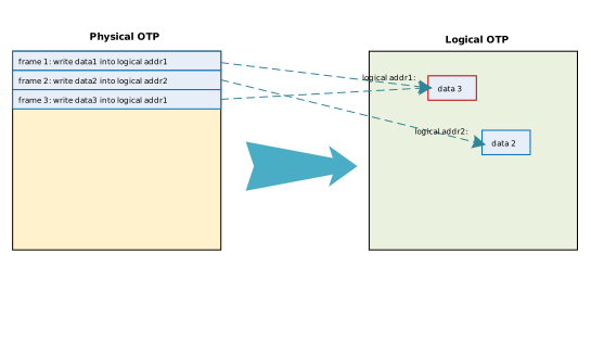
Each block of data in the logical zone occupies one frame in the mapping zone. The hardware sequentially scans the content of each frame in the mapping zone and maps the data to the logical zone. When multiple frames map to the same address in the logical zone, the hardware uses the data from the last frame, which allows the logical zone to be modified multiple times.
Note
Refer to the corresponding User Manual for the detailed mapping relationship between the logical zone and the mapping zone.
Each modification to the value of the logical zone occupies one frame in the mapping zone. Therefore, when the mapping zone is full, the logical zone can no longer be modified.
The layout of the logical zone has been predefined by Realtek and includes the system data zone, user-defined MTP zone, calibration zone, etc.
Logical Zone Partition |
Address |
Description |
Usage |
|---|---|---|---|
System data zone |
(0x000-0x01F, 32 bytes) |
Stores system data. |
|
Wi-Fi Calibration zone |
(0x020-0x13F, 288 bytes) |
Stores Wi-Fi calibration data. |
- |
HCI-USB |
(0x150-0x15F, 16 bytes) |
Stores configuration data related to USB devices. |
- |
Cap-Touch Calibration zone |
(0x160-0x16F, 16 bytes) |
Stores Cap-Touch calibration data. |
- |
User-defined MTP zone |
(0x170-0x19F, 48 bytes) |
For user’s free use. |
|
BT parameters zone |
(0x1B0-0x1FF, 80 bytes) |
Stores BT parameters. |
- |
Logical Zone Partition |
Address |
Description |
Usage Instructions |
|---|---|---|---|
System Data Zone |
(0x000-0x01F, 32 Bytes) |
Stores system data. |
|
Wi-Fi Calibration Zone |
(0x020-0x14F, 304 Bytes) |
Stores Wi-Fi calibration data. |
- |
Cap-Touch Calibration Zone |
(0x160-0x16F, 16 Bytes) |
Stores Cap-Touch calibration data. |
- |
User-defined MTP Zone |
(0x170-0x19F, 48 Bytes) |
Free for user use. |
|
BT Parameters Zone |
(0x1B0-0x1FF, 80 Bytes) |
Used for BT parameters. |
- |
Logical Zone Partition |
Address |
Description |
Usage Instructions |
|---|---|---|---|
System Data Zone |
(0x000-0x01F, 32 Bytes) |
Stores system data. |
|
Wi-Fi Calibration Zone |
(0x020-0x14F, 304 Bytes) |
Stores Wi-Fi calibration data. |
- |
Cap-Touch Calibration Zone |
(0x160-0x16F, 16 Bytes) |
Stores Cap-Touch calibration data. |
- |
User-defined MTP Zone |
(0x170-0x19F, 48 Bytes) |
Free for user use. |
|
BT Parameters Zone |
(0x1B0-0x1FF, 80 Bytes) |
Used for BT parameters. |
- |
Logical Zone Partition |
Address |
Description |
Usage Instructions |
|---|---|---|---|
System Data Zone |
(0x000-0x01F, 32 Bytes) |
Stores system data. |
|
Wi-Fi Calibration Zone |
(0x020-0x14F, 304 Bytes) |
Stores Wi-Fi calibration data. |
- |
Cap-Touch Calibration Zone |
(0x160-0x16F, 16 Bytes) |
Stores Cap-Touch calibration data. |
- |
User-defined MTP Zone |
(0x170-0x19F, 48 Bytes) |
Free for user use. |
|
BT Parameters Zone |
(0x1B0-0x1FF, 80 Bytes) |
Used for BT parameters. |
- |
Logical Zone Partition |
Address |
Description |
Usage Instructions |
|---|---|---|---|
System Data Zone |
(0x000-0x01F, 32 Bytes) |
Stores system data. |
|
Wi-Fi Calibration Zone |
(0x020-0x14F, 304 Bytes) |
Stores Wi-Fi calibration data. |
- |
Cap-Touch Calibration Zone |
(0x160-0x16F, 16 Bytes) |
Stores Cap-Touch calibration data. |
- |
User-defined MTP Zone |
(0x170-0x19F, 48 Bytes) |
Free for user use. |
|
BT Parameters Zone |
(0x1B0-0x1FF, 80 Bytes) |
Used for BT parameters. |
- |
Logical Zone Partition |
Address |
Description |
Usage Instructions |
|---|---|---|---|
System Data Zone |
(0x000-0x01F, 32 Bytes) |
Stores system data. |
|
Wi-Fi Calibration Zone |
(0x020-0x13F, 288 Bytes) |
Stores Wi-Fi calibration data. |
- |
ADC Calibration Zone |
(0x140-0x14F, 16 Bytes) |
Stores ADC calibration data. |
- |
HCI-USB |
(0x150-0x15F, 16 Bytes) |
Stores USB device related configuration data. |
- |
Cap-Touch Calibration Zone |
(0x160-0x16F, 16 Bytes) |
Stores Cap-Touch calibration data. |
- |
User-defined MTP Zone |
(0x170-0x19F, 48 Bytes) |
Free for user use. |
|
BT Parameters Zone |
(0x1B0-0x1FF, 80 Bytes) |
Stores BT parameters. |
- |
Logical Zone Partition |
Address |
Description |
Usage Instructions |
|---|---|---|---|
System Data Zone |
(0x000-0x01F, 32 Bytes) |
Stores system data. |
|
Wi-Fi Calibration Zone |
(0x020-0x14F, 304 Bytes) |
Stores Wi-Fi calibration data. |
- |
User-defined MTP Zone |
(0x170-0x19F, 48 Bytes) |
Free for user use. |
|
BT Parameters Zone |
(0x1B0-0x1FF, 80 Bytes) |
Stores BT parameters. |
- |
HCI-SDIO |
(0x200-0x29F, 160 Bytes) |
Stores SDIO device related configuration data. |
- |
HCI-USB |
(0x2A0-0x2FF, 288 Bytes) |
Stores USB device related configuration data. |
- |
Ethernet MAC Address Zone |
(0x300-0x305, 6 Bytes) |
Used to store the Ethernet MAC address used by RMII. |
- |
Logical Zone Partition |
Address |
Description |
Usage Instructions |
|---|---|---|---|
System Data Zone |
(0x000-0x01F, 32 Bytes) |
Stores system data. |
|
Wi-Fi Calibration Zone |
(0x020-0x14F, 304 Bytes) |
Stores Wi-Fi calibration data. |
- |
User-defined MTP Zone |
(0x170-0x19F, 48 Bytes) |
Free for user use. |
|
BT Parameters Zone |
(0x1B0-0x1FF, 80 Bytes) |
Stores BT parameters. |
- |
HCI-SDIO |
(0x200-0x29F, 160 Bytes) |
Stores SDIO device related configuration data. |
- |
Logical Zone Partition |
Address |
Description |
Usage |
|---|---|---|---|
Wi-Fi/BT/Analog zone |
(0x000-0x1FF, 512 bytes) |
Stores Wi-Fi, BT, and analog calibration data. |
- |
AON zone |
(0x200-0x27F, 128 bytes) |
Stores Always-On calibration and configuration data. |
- |
REGU zone |
(0x280-0x2DF, 96 bytes) |
Stores regulator calibration data. |
- |
XTAL zone |
(0x2E0-0x30F, 48 bytes) |
Stores crystal oscillator calibration data. |
- |
AON Pad zone |
(0x310-0x32F, 32 bytes) |
Stores AON pad configuration data. |
- |
BANDGAP zone |
(0x330-0x34F, 32 bytes) |
Stores bandgap calibration data. |
- |
SPIC PHY/BPGM/PSRAMC zone |
(0x350-0x38F, 64 bytes) |
Stores SPIC PHY, BPGM, and PSRAMC configuration data. |
- |
PLL track zone |
(0x390-0x68F, 768 bytes) |
Stores PLL track data for USB, Ethernet MAC, and ROM patch. |
- |
System for SW zone |
(0x690-0x6AF, 32 bytes) |
Stores system software configuration data. |
|
PLL zone |
(0x6B0-0x70F, 96 bytes) |
Stores PLL calibration data. |
- |
Reserved zone |
(0x710-0x74F, 64 bytes) |
Reserved. |
- |
PON Pad zone |
(0x750-0x79F, 80 bytes) |
Stores PON pad configuration data. |
- |
Reserved zone |
(0x7A0-0x7FF, 96 bytes) |
Reserved. |
- |

