Introduction
There are multiple processors integrated into the chip. The Inter-Processor Communication (IPC) hardware establishes dedicated communication channels between every two processors.
The IPC provides a set of registers for each processor and realizes inter-processor communication via interrupts. Additionally, interrupts can be independently masked by each processor to support polled-mode operation.
The IPC communication data must be located in a common memory, which is not part of the IPC block.
Features
{{IC_PARAM_IPC_CH}}TRx channels between every two processors
{{IC_PARAM_IPC_CH}}TRx channels between every two processors
{{IC_PARAM_IPC_CH}}TRx channels between every two processors
{{IC_PARAM_IPC_CH}}TRx channels between every two processors
{{IC_PARAM_IPC_CH}}TRx channels between every two processors
{{IC_PARAM_IPC_CH}}TRx channels between every two processors
{{IC_PARAM_IPC_CH}}TRx channels between every two processors
{{IC_PARAM_IPC_CH}}TRx channels between every two processors
Independent trx channels
Channel-independent interrupt control
Support Rx channel full interrupt
Support Tx channel empty interrupt
Shared memory
Block Diagram
The IPC provides simple communication between every two processors. It can use shared SRAM to transmit information to other CPU(s). The system block diagram of IPC is shown in the following figure.

The IPC submodule structure of each processor is the same. The following figure summarizes the submodule’s structure of IPC_CPUm.
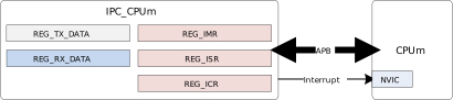
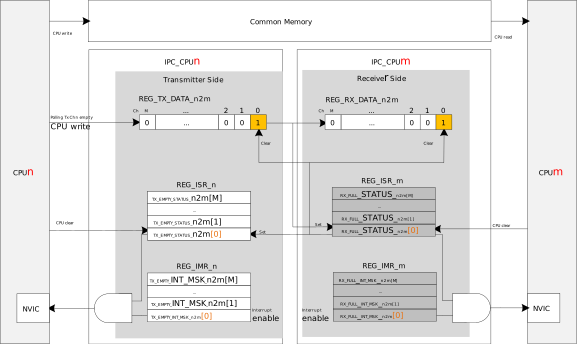
Between every two processors, one processor has 2 sets of communication channels, 1 set for transmitting data (Tx) to the other processor by writing Tx Data Register, and the other set for receiving data (Rx) from the other processor by checking Rx Data Register.
In addition to data registers, there are also interrupt-related registers:
Interrupt Status Register (ISR) is used to present current channel Tx empty or Rx full status change.
Interrupt Mask Register (IMR) is used to enable interrupts for Tx empty or Rx full.
Interrupt Clear Register (ICR) is used to clear the corresponding interrupt status.
The following figure demonstrates message transmission from CPUn to CPUm.