Functional Description
Message Transmit
Between every two processors, one processor has 2 sets of channels to communicate with the other processor. Channel index of Tx channels and the corresponding Rx channels are one-to-one mapping.
REG_TX_DATA of CPUn is used by CPUn to transmit data to CPUm, once
1is written to the channel x (x could be 0 ~ M, where M means max channel index), the corresponding bit in REG_RX_DATA of CPUm will be set. The Rx full bit of channel x in REG_ISR of CPUm will be set at the same time.Writing
1to channel x in REG_ISR of CPUm clears the Rx full interrupt of channel x, the corresponding channel x Tx empty interrupt bit in REG_ISR of CPUn will be set automatically.
IPC message transmitting mapping shows the IPC transmit mapping from CPUn to CPUm, and IPC message receiving mapping shows the IPC mapping from CPUm to CPUn after receiving data.
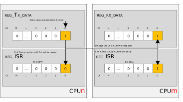
IPC message transmitting mapping
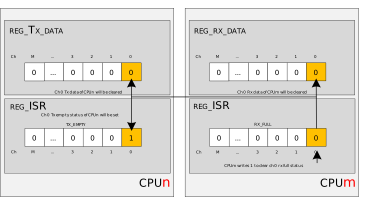
IPC message receiving mapping
IPC without Handshake
As there are Rx Full and Tx Empty interrupts for each processor, these functions can be used to realize message transmission and handshake.
IPC message transmission flow without handshake shows the interrupt messaging protocol of IPC without waiting for a handshake from receiver, and steps are summarized in IPC message transmission steps without handshake. It takes the message transmission from CPUn to CPUm for example.
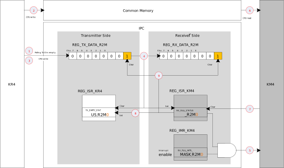
IPC message transmission flow without handshake
Step |
Description |
|---|---|
1 |
Check the Tx data status of the channel 0 in CPUn IPC Tx Data Register |
2 |
CPUn writes data to the Common Memory |
3 |
Write |
4 |
The CPUn IPC Tx Data Register write operation
|
5 |
If the Rx Full interrupt mask is enabled in CPUm Interrupt Mask Register, a Rx Full interrupt request will be generated to CPUm. |
6 |
After checking Rx Full channel, CPUm performs a data read from the corresponding Common Memory |
7 |
After finishing the interrupt handler, CPUm writes |
8 |
The CPUm Interrupt Status Register write operation
|
9 |
Clear the channel 0 bit in CPUm IPC Rx Data Register and CPUn IPC Tx Data Register automatically |
IPC with Handshake
IPC message transmission flow with handshake shows the interrupt messaging protocol of IPC with waiting for a handshake from receiver, and steps are summarized in IPC message transmission steps with handshake. It takes the message transmission from CPUn to CPUm for example.
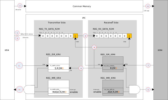
IPC message transmission flow with handshake
Step |
Description |
|---|---|
1 |
Check the Tx data status of the channel 0 in CPUn IPC Tx Data Register |
2 |
CPUn writes data to the Common Memory |
3 |
Write |
4 |
The CPUn IPC Tx Data Register write operation
|
5 |
If the Rx Full interrupt mask is enabled in CPUm Interrupt Mask Register, a Rx Full interrupt request will be generated to CPUm. |
6 |
After checking Rx Full channel, CPUm performs a data read from the corresponding Common Memory |
7 |
After finishing the interrupt handler, CPUm write |
8 |
The IPC Interrupt Status Register write operation
|
9 |
Clear the channel 0 bit in CPUm IPC Rx Data Register and CPUn IPC Tx Data Register automatically |
10 |
If Tx Empty mask is enabled in CPUn Interrupt Mask Register, the setting of the Tx Empty bit in the CPUn Status Register generates a Tx Empty interrupt to CPUn |
11 |
CPUn writes |
Hardware Semaphore
Overview
The hardware semaphore is used for a mutual exclusion mechanism. It can be accessed by the cores in an atomic operation.
Traditionally, the software takes three steps to use the semaphore: read -> write -> read.
The first read operation of the CPU is to poll the current semaphore to check whether it is occupied or not.
If this semaphore is free, the CPU will compete it by writing.
The last read operation is to check whether the CPU has already occupied this semaphore because maybe several CPUs or threads write to compete the same semaphore.
The above flow executed by software is offloaded to hardware. The following figure illustrates the hardware semaphore mechanism.
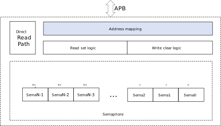
The address mapping is responsible for mapping the
Nbit semaphore status toNx 4 address space, whereNrepresents the total number of hardware semaphore.The read set logic is responsible for determining the status of the semaphore to be read after receiving the read request. If the corresponding semaphore register is 0, the read set logic will set the semaphore register first, then return 0 to the read request.
The write clear logic is responsible for clearing the status of the semaphore to 0 after receiving write request.
The semaphore register has
Nbits, and each bit in the register represents a semaphore. This register can be read directly, or read/written through the address mapped register.If the semaphore register is read through the address mapped register, the status of only one bit can be read at a time, and this bit will be set synchronously when it is 0.
If the semaphore register is read directly, the read does not change the status of the semaphore, and all the
Nbits can be read at a time.
N equals {{IC_PARAM_IPC_SEMA}}.
N equals {{IC_PARAM_IPC_SEMA}}.
N equals {{IC_PARAM_IPC_SEMA}}.
N equals {{IC_PARAM_IPC_SEMA}}.
N equals {{IC_PARAM_IPC_SEMA}}.
N equals {{IC_PARAM_IPC_SEMA}}.
N equals {{IC_PARAM_IPC_SEMA}}.
N equals {{IC_PARAM_IPC_SEMA}}.
Address Mapping
If the bit[0] of the semaphore register can be acquired and released through the base address of address mapping, the bit[1] can be acquired and released through (base address + 4) accordingly. Thus the address of the entire access window ranges from 0 to ( N x 4 - 1), where N is the total number of hardware semaphore.
Acquire Flow
If the software wants to acquire the semaphore 0, it can directly read the base address of the access window register.
If the bit is 0 when the hardware receives the read request, the hardware will set this bit and return 0 synchronously. At this time, the acquire flow will be regarded as successful by software.
If the bit is 1 when the hardware receives the read request, the hardware will directly return 1. At this time, the acquire flow will be regarded as failed by software.
Release Flow
If the software wants to release the semaphore 0, it can directly write the base address of the access window register. The hardware will clear this bit after receiving the write command.
Inquire Flow
If the software wants to inquire the semaphore status, it can directly read the semaphore registers (without address mapping). This operation only returns the semaphore status, but does not change it.