Introduction
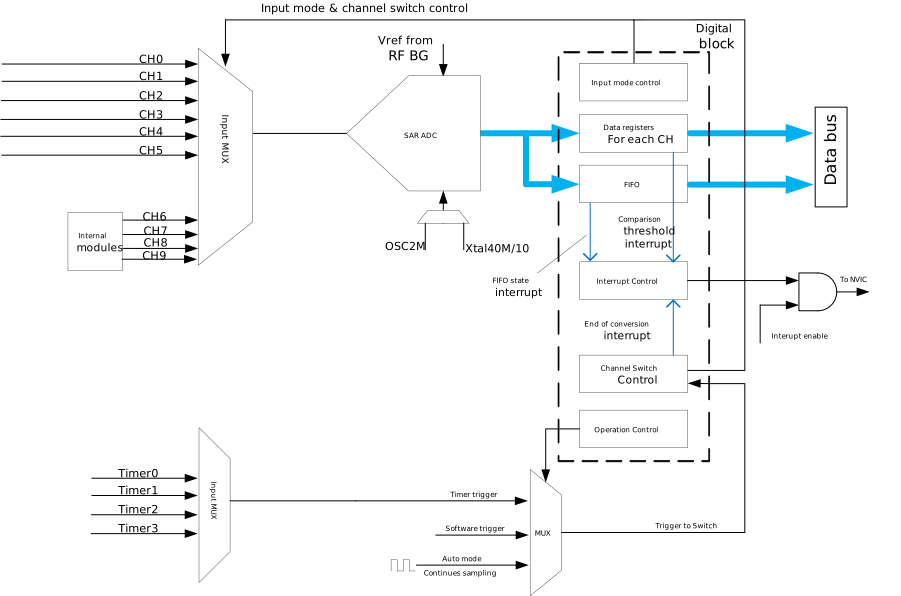
Analog-to-digital converter (ADC) is a successive-approximation register (SAR) ADC, which includes external channels and internal channels.
ADC supports multiple sampling modes, e.g. continuous sampling, software-trigger sampling and timer-trigger sampling. The ADC conversion result is stored in the result register and can be read on demand.
Features
The features of ADC are listed below:
Resolution: 12-bit SAR
Available channel number
7x external channels and 1x VBAT channel
3x internal channels
Input voltage range
External channels: 0V ~ min(VAH_ADC, 3.3 V)
VBAT channel: 0V ~ 5V (for battery)
ADC supply requirement (VAH_ADC): 1.8V to 3.63 V
Contain 64 x 20-bit FIFO entries for storing the conversion results
Multiple sampling mode:
Auto continuous sampling
Hardware oversample for higher SNR
Available channel number
6x external channels
3x internal channels
Input voltage range: 0V ~ min(VAH_AUX, 3.3 V)
ADC supply requirement (VAH_AUX): 2.97 V to 3.63 V
Contain 64 x 16-bit FIFO entries for storing the conversion results
Multiple sampling mode:
Auto continuous sampling
Software-trigger sampling
Timer-trigger sampling
Available channel number
6x external channels
3x internal channels
Input voltage range: 0V ~ min(VAH_AUX, 3.3 V)
ADC supply requirement (VAH_AUX): 2.97 V to 3.63 V
Contain 64 x 16-bit FIFO entries for storing the conversion results
Multiple sampling mode:
Auto continuous sampling
Software-trigger sampling
Timer-trigger sampling
Available channel number
6x external channels
3x internal channels
Input voltage range: 0V ~ min(VAH_AUX, 3.3 V)
ADC supply requirement (VAH_AUX): 2.97 V to 3.63 V
Contain 64 x 16-bit FIFO entries for storing the conversion results
Multiple sampling mode:
Auto continuous sampling
Software-trigger sampling
Timer-trigger sampling
Available channel number
6x external channels
3x internal channels
Input voltage range: 0V ~ min(VAH_AUX, 3.3 V)
ADC supply requirement (VAH_AUX): 2.97 V to 3.63 V
Contain 64 x 16-bit FIFO entries for storing the conversion results
Multiple sampling mode:
Auto continuous sampling
Software-trigger sampling
Timer-trigger sampling
Available channel number
6x external channels and 1x VBAT channel
3x internal channels
Input voltage range
External channels: 0V ~ 1.8V
VBAT channel: 0V ~ 5V (for battery)
ADC supply requirement (VAH_PLL): 2.97 V to 3.63 V
Contain 64 x 16-bit FIFO entries for storing the conversion results
Multiple sampling mode:
Auto continuous sampling
Software-trigger sampling
Timer-trigger sampling
Available channel number
8x external channels
4x internal channels
Input voltage range: 0V ~ min(VAH_ADC, 3.3 V)
ADC supply requirement (VAH_ADC): 2.97 V to 3.63 V
Contain 64 x 20-bit FIFO entries for storing the conversion results
Multiple sampling mode:
Auto continuous sampling
Software-trigger sampling
Timer-trigger sampling
Hardware oversample for higher SNR
Available channel number
6x external channels
4x internal channels
Input voltage range: 0V ~ min(VAH_ADC, 3.3 V)
ADC supply requirement (VAH_ADC): 2.97 V to 3.63 V
Contain 64 x 20-bit FIFO entries for storing the conversion results
Multiple sampling mode:
Auto continuous sampling
Software-trigger sampling
Timer-trigger sampling
Hardware oversample for higher SNR
Configurable ADC clock source and sampling rate
Configurable channel switch order and channel number through the channel list
Individual channel register for storing the conversion results and status
Built-in calibration
Multiple interrupts:
End of channel list scan
End of the specific channel scan
Independent comparison event of each channel
Data overwrite event
FIFO empty, FIFO overflow and FIFO full status
Block Diagram
The following figure shows the block diagram of the 12-bit ADC.