Functional Description
Independent Watchdog Timer
Debug Pause
The IWDG keeps counting when one of the CPUs is active (both clock and function are enabled) and no CPU is in debug mode. The IWDG clock and function enable diagram is illustrated in the following figure.
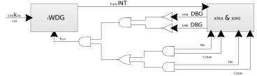
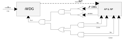
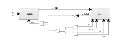
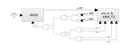
The AON WDT automatically pauses counting when the corresponding CPU (KM0, KM4 or CA32) is in debug mode.
Reset
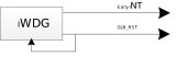
The IWDG has the highest privilege. An IWDG timeout will trigger GLB_RST, and this reset signal resets the entire system, including all processors and almost all peripherals. Only a very few peripherals are not reset by GLB_RST, such as RTC and AON PAD.
The IWDG reset control is illustrated below.
System Watchdog Timer
Debug Pause
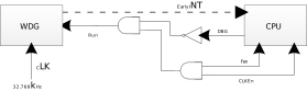
When the corresponding CPU enters debug mode or is shut down, the SWDG automatically pauses counting, but its state is maintained.
The SWDG clock and function enable diagram is illustrated below.
Reset
WDG timeout or feeding outside the window will trigger GLB_RST by default. This reset signal will reset the entire system, including all processors and almost all peripherals. Only very few peripherals will not be reset by GLB_RST, such as RTC and AON PAD. Some SoC system watchdogs support configuration to reset only the corresponding CPU under specific conditions.
Low-power Mode
For IWDG, whether the IWDG can keep running or gating in sleep mode depends on the LPEN bit.
If LPEN is cleared, the hardware will gate the clock for IWDG internally, and IWDG will be frozen with all status maintained.
If LPEN is enabled, IWDG will keep counting down, wake up the system if the early interrupt event fires, and reset the system if the watchdog triggers.
Each system watchdog timer can maintain its registers but keep freezing in sleep mode. Counting down will resume after leaving sleep.
However, in deep-sleep mode, the hardware will disable IWDG, and the system watchdog timers will be powered off.
Register Protection
After the watchdog timer is enabled, WDG_MKEYR is the only register that can be accessed at any time. Other registers can be accessed only when WDG_MKEYR equals 0x6969.
Early Interrupt
The watchdog timer can trigger an interrupt to wake up the system or inform the system that a watchdog reset is coming. This interrupt can be enabled by setting appropriate values to EARLY_INT_CNT and EIE. When the down-counter (WDGCNT) reaches the value of (EARLY_INT_CNT -1), the interrupt fires.
It is possible to change the early interrupt threshold after EIE is enabled, by performing the following sequences:
Enable register access by writing 0x6969 into the WDG_MKEYR register
Disable the EIE bit of the WDG_CR register
Wait for EVU = 0, EVU is also located in the WDG_CR register
Program the early interrupt threshold and enable the early interrupt in the WDG_CR register
Wait for EVU = 0
Refresh the counter with WDG_RLR [15:0], and write-protect registers by writing 0x5A5A into the WDG_MKEYR register
Window Protection
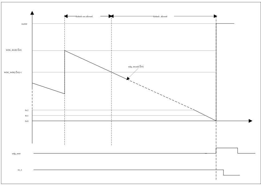
The watchdog timer can also work as a window watchdog by setting the appropriate window in WDG_WIN. If the reload operation is performed while the counter is greater than WDG_WIN [15:0], a reset is generated. The default value of WDG_WIN is 0x0000FFFF, if not updated, the window option is disabled.
To prevent malicious attacks from changing the window value, the window value can only be set before watchdog enable. Once the watchdog is enabled, the value cannot be changed. Due to the inaccuracy of the source clock, we do not suggest enabling the window protection function of IWDG.
The watchdog window function watchdog feeding timing diagram is illustrated below.
Timeout Configuration
The watchdog timeout period is determined by WDG_RLR [15:0] RELOAD and WDG_RLR [23:16] Prescaler. The calculation formula is RELOAD × Prescaler / WDG_CLK.
To configure the timeout period, perform the following sequences:
Enable register access by writing 0x6969 into the WDG_MKEYR register
Wait for EVU = 0, EVU is also located in the WDG_CR register
Program the WDG_RLR register
Wait for EVU = 0
Write-protect registers by writing 0x5A5A into the WDG_MKEYR register
Note
Once IWDG is enabled, the timeout period can only be shortened by decreasing the RELOAD value; increasing the timeout period is not allowed.
Once the system watchdog is enabled, the timeout period cannot be modified.
Once IWDG is enabled, the timeout period can only be shortened by decreasing the RELOAD value; increasing the timeout period is not allowed.
Once the system watchdog is enabled, the timeout period cannot be modified.
Once IWDG is enabled, the timeout period can only be shortened by decreasing the RELOAD value; increasing the timeout period is not allowed.
Once the system watchdog is enabled, the timeout period cannot be modified.
Once IWDG is enabled, the timeout period can only be shortened by decreasing the RELOAD value; increasing the timeout period is not allowed.
Once the system watchdog is enabled, the timeout period cannot be modified.
Once IWDG is enabled, the timeout period can only be shortened by decreasing the RELOAD value; increasing the timeout period is not allowed.
Once the system watchdog is enabled, the timeout period cannot be modified.
Once IWDG is enabled, the timeout period cannot be modified.
Once the system watchdog is enabled, the timeout period cannot be modified.
The default RELOAD value is 0xFFFF, corresponding to a timeout period of 64 seconds.
Once IWDG is enabled, the timeout period can only be shortened by decreasing the RELOAD value; increasing the timeout period is not allowed.
Once the system watchdog is enabled, the timeout period cannot be modified.
The AON WDT timeout period is calculated as
CNT × (PRE_SCALER + 1) × 64 / 100 kHz. The maximum timeout period is about 41.9 seconds whenPRE_SCALERis 0.Software feeds the AON WDT by writing 1 to the
WDT_CLRbit.
Watchdog Refresh
Refresh the counter with WDG_RLR [15:0], and write-protect registers by writing 0x5A5A into the WDG_MKEYR register.
Update Indication
Because the watchdog and its registers work in different clock domains, and frequencies are varied, cross-clock synchronization must be considered. In order to prevent the subsequent write operation from affecting the previous operation, two status flags are introduced in the following table.
Bit |
Flag |
Description |
|---|---|---|
EVU |
Watchdog early interrupt function update |
This bit is set by hardware to indicate that an update of the interrupt threshold (EICNT[15:0]) is ongoing or an update of the EIE is ongoing. It is reset by hardware when the update operation is completed. The EICNT[15:0] and EIE fields can be updated only when the EVU bit is reset. |
RVU |
Watchdog counter value update |
This bit is set by hardware to indicate that the reload operation is ongoing. It is reset by hardware when the counter update operation is completed. The reload value can be updated only when the RVU bit is reset. |
Before writing to the watchdog register, software needs to check these flags to ensure no conflict and disorder issues.