Functional Description
Operation Flow
The operation flow of the thermal sensor is shown in the following figure.

The operation flow is mainly divided into an initialization phase and a continuous monitoring phase. The system continuously compares the sensor output temperature ( TM_OUT ) with three predefined thresholds to adopt different software and hardware protection mechanisms. The specific flow is as follows:
Initialization Phase
After the system starts, it first enters the initialization flow. During this phase, the system executes the following operations sequentially:
Configure the relevant parameters of the Analog-to-Digital Converter (ADC).
Set temperature thresholds and enable the threshold comparison function. The temperature threshold is a two’s complement value corresponding to the Celsius temperature (1 sign bit + 8 integer bits); for example, the threshold for 125°C is 0x7D, and the threshold for -40°C is 0x1D8.
Enable the temperature sensor module (this function is enabled by default in the MP version).
Enable interrupts to prepare for subsequent temperature warnings and protective actions.
Continuous Monitoring Phase
After initialization is complete, the system enters a continuous temperature threshold determination loop, sequentially performing the following three state detections according to priority:
Over-Temperature Protection Determination (TM_OUT >= TM_HIGH_PT_THR)
The system first determines whether the sensor output temperature ( TM_OUT ) is greater than or equal to the over-temperature protection threshold ( TM_HIGH_PT_THR ).
If the condition is met: Trigger a thermal reset.
Hardware behavior: The hardware automatically loads the timing period value in
TM_TIMERinto the AON timer, with the timer unit being 0.65s. The AON timer is started after the thermal reset is executed, and the system is rebooted after the timer expires.Software behavior: The system will continue to monitor the temperature after rebooting. If the temperature drops below the user-configured safe threshold, all cores will resume normal operation; otherwise, the Application Processor (AP) will remain in a halted state.
If the condition is not met: Proceed to the next level of determination.
High-Temperature Warning Determination (TM_OUT >= TM_HIGH_WT_THR)
If a thermal reset is not triggered, the system then determines whether the temperature is greater than or equal to the high-temperature warning threshold ( TM_HIGH_WT_THR ).
If the condition is met: Trigger a high-temperature warning interrupt. The system will issue an interrupt request to the CPU, and it is recommended that the user implement strategies such as lowering the main frequency or reducing the operating speed to achieve physical cooling of the system.
If the condition is not met: Proceed to the next level of determination.
Low-Temperature Warning Determination (TM_OUT <= TM_LOW_THR)
If no high-temperature protection mechanisms are triggered, the system further determines whether the temperature is less than or equal to the low-temperature warning threshold ( TM_LOW_THR ).
If the condition is met: Trigger a low-temperature warning interrupt, issue an interrupt to the CPU, and report the low-temperature warning.
If the condition is not met: The system performs no action and directly returns to the starting point of the monitoring loop to restart the next round of
TM_OUTthreshold determination.
The entire process loops repeatedly to ensure reliable operation of the system within the set safe temperature range.
Acquiring Temperature
When TM_BIT_EN_LATCH is 0, the Celsius temperature measurement result of the thermal sensor is typically stored in the TM_RESULT register in two’s complement format, with an effective data width of 19 bits, including 1 sign bit, 8 integer bits, and 10 fractional bits.
Data Conversion Process in Positive Temperature Zone
When the original data is in the [0, 0x3FFFF] range, the Celsius temperature value is non-negative. The conversion rules are as follows:
Integer part extraction: [17:10] represents the integer part of the Celsius temperature value.
Fractional part extraction: [9:0] represents the fractional part of the Celsius temperature value, which is cast to a floating-point type and divided by 1024.0 to obtain the true fractional value.
Result synthesis: Directly add the above integer part and fractional part to obtain the actual floating-point Celsius temperature value.
Data Conversion Process in Negative Temperature Zone
When the original data is in the [0x40000, 0x7FFFF] range, the Celsius temperature value is negative. The conversion rules are as follows:
Inverse two’s complement operation: Calculate the absolute value according to abs_val = 0x80000 - result.
Absolute value separation: After obtaining the absolute value abs_val, reuse the data separation logic from the positive temperature zone to extract its integer part and fractional part respectively.
Negative sign restoration: Add the integer and fractional parts together, then prepend a negative sign to the sum to obtain the actual floating-point Celsius temperature value.
Interrupt
The thermal sensor supports the following interrupts:
High-temperature warning interrupt (TM_BIT_IMR_TM_HIGH_WT): Generated when the thermal sensor detects that the temperature reaches or exceeds the high-temperature warning threshold. This interrupt is maskable and is disabled by default.
Low-temperature warning interrupt (TM_BIT_IMR_TM_LOW_WT): Generated when the thermal sensor detects that the temperature reaches or drops below the low-temperature warning threshold. This interrupt is maskable and is disabled by default.
Power-on Flow
Since the thermal sensor mainly uses an analog circuit to measure temperature, and the analog circuit takes a while to stabilize after power on, additional operations are needed to get the correct temperature.
The thermal sensor keeps power on in default state. When the system powers on, the thermal sensor is on too. But the analog circuit is not stable now, so the current temperature is not correct. To fix this problem, latch is configured to enable by default. After 10 cycles, latch is disabled automatically.
The power-on flow of the thermal sensor can be described as the following figure.

Power-on temperature (temp_out_poweron) is the first temperature measured after latch disabled with thermal stabilized. Also tm_max and tm_min start recording only after thermal is stable.
Registers Access Control
The values of thermal registers can be obtained directly by reading the registers’ addresses. Also, most of the thermal registers’ bits can be programmed by writing values to the registers’ addresses directly.
The write access for five specific fields is different from that of other fields. The fields include tm_pow, tm_powcut, tm_rstb, tm_highcmp_pt_en and tm_high_pt_thr. Write flow of these fields is illustrated in the following figure.

The grant code protects write access to special fields to prevent incorrect operations from disabling the thermal sensor, deactivating over-temperature protection, or setting an incorrect high-temperature protection threshold.
Note
Configuration with TM Oversampling Ratio (OSR) greater than or equal to three is not supported.
Operation Flow
The operation flow of the thermal sensor is shown in the following figure.
The operation flow is mainly divided into an initialization phase and a continuous monitoring phase. The system continuously compares the sensor output temperature ( TM_OUT ) with three predefined thresholds to adopt different software and hardware protection mechanisms. The specific flow is as follows:
Initialization Phase
After the system starts, it first enters the initialization flow. During this phase, the system executes the following operations sequentially:
Configure the relevant parameters of the Analog-to-Digital Converter (ADC).
Set temperature thresholds and enable the threshold comparison function. The temperature threshold is a two’s complement value corresponding to the Celsius temperature (1 sign bit + 8 integer bits); for example, the threshold for 125°C is 0x7D, and the threshold for -40°C is 0x1D8.
Enable the temperature sensor module (this function is enabled by default in the MP version).
Enable interrupts to prepare for subsequent temperature warnings and protective actions.
Continuous Monitoring Phase
After initialization is complete, the system enters a continuous temperature threshold determination loop, sequentially performing the following three state detections according to priority:
Over-Temperature Protection Determination (TM_OUT >= TM_HIGH_PT_THR)
The system first determines whether the sensor output temperature ( TM_OUT ) is greater than or equal to the over-temperature protection threshold ( TM_HIGH_PT_THR ).
If the condition is met: Trigger a thermal reset.
Hardware behavior: The hardware automatically loads the timing period value in
TM_TIMERinto the AON timer, with the timer unit being 0.65s. The AON timer is started after the thermal reset is executed, and the system is rebooted after the timer expires.Software behavior: The system will continue to monitor the temperature after rebooting. If the temperature drops below the user-configured safe threshold, all cores will resume normal operation; otherwise, the Application Processor (AP) will remain in a halted state.
If the condition is not met: Proceed to the next level of determination.
High-Temperature Warning Determination (TM_OUT >= TM_HIGH_WT_THR)
If a thermal reset is not triggered, the system then determines whether the temperature is greater than or equal to the high-temperature warning threshold ( TM_HIGH_WT_THR ).
If the condition is met: Trigger a high-temperature warning interrupt. The system will issue an interrupt request to the CPU, and it is recommended that the user implement strategies such as lowering the main frequency or reducing the operating speed to achieve physical cooling of the system.
If the condition is not met: Proceed to the next level of determination.
Low-Temperature Warning Determination (TM_OUT <= TM_LOW_THR)
If no high-temperature protection mechanisms are triggered, the system further determines whether the temperature is less than or equal to the low-temperature warning threshold ( TM_LOW_THR ).
If the condition is met: Trigger a low-temperature warning interrupt, issue an interrupt to the CPU, and report the low-temperature warning.
If the condition is not met: The system performs no action and directly returns to the starting point of the monitoring loop to restart the next round of
TM_OUTthreshold determination.
The entire process loops repeatedly to ensure reliable operation of the system within the set safe temperature range.
Acquiring Temperature
When TM_BIT_EN_LATCH is 0, the Celsius temperature measurement result of the thermal sensor is typically stored in the TM_RESULT register in two’s complement format, with an effective data width of 19 bits, including 1 sign bit, 8 integer bits, and 10 fractional bits.
Data Conversion Process in Positive Temperature Zone
When the original data is in the [0, 0x3FFFF] range, the Celsius temperature value is non-negative. The conversion rules are as follows:
Integer part extraction: [17:10] represents the integer part of the Celsius temperature value.
Fractional part extraction: [9:0] represents the fractional part of the Celsius temperature value, which is cast to a floating-point type and divided by 1024.0 to obtain the true fractional value.
Result synthesis: Directly add the above integer part and fractional part to obtain the actual floating-point Celsius temperature value.
Data Conversion Process in Negative Temperature Zone
When the original data is in the [0x40000, 0x7FFFF] range, the Celsius temperature value is negative. The conversion rules are as follows:
Inverse two’s complement operation: Calculate the absolute value according to abs_val = 0x80000 - result.
Absolute value separation: After obtaining the absolute value abs_val, reuse the data separation logic from the positive temperature zone to extract its integer part and fractional part respectively.
Negative sign restoration: Add the integer and fractional parts together, then prepend a negative sign to the sum to obtain the actual floating-point Celsius temperature value.
Interrupt
The thermal sensor supports the following interrupts:
High-temperature warning interrupt (TM_BIT_IMR_TM_HIGH_WT): Generated when the thermal sensor detects that the temperature reaches or exceeds the high-temperature warning threshold. This interrupt is maskable and is disabled by default.
Low-temperature warning interrupt (TM_BIT_IMR_TM_LOW_WT): Generated when the thermal sensor detects that the temperature reaches or drops below the low-temperature warning threshold. This interrupt is maskable and is disabled by default.
Power-on Flow
Since the thermal sensor mainly uses an analog circuit to measure temperature, and the analog circuit takes a while to stabilize after power on, additional operations are needed to get the correct temperature.
The thermal sensor keeps power on in default state. When the system powers on, the thermal sensor is on too. But the analog circuit is not stable now, so the current temperature is not correct. To fix this problem, latch is configured to enable by default. After 10 cycles, latch is disabled automatically.
The power-on flow of the thermal sensor can be described as the following figure.
Power-on temperature (temp_out_poweron) is the first temperature measured after latch disabled with thermal stabilized. Also tm_max and tm_min start recording only after thermal is stable.
Registers Access Control
The values of thermal registers can be obtained directly by reading the registers’ addresses. Also, most of the thermal registers’ bits can be programmed by writing values to the registers’ addresses directly.
The write access for five specific fields is different from that of other fields. The fields include tm_pow, tm_powcut, tm_rstb, tm_highcmp_pt_en and tm_high_pt_thr. Write flow of these fields is illustrated in the following figure.
The grant code protects write access to special fields to prevent incorrect operations from disabling the thermal sensor, deactivating over-temperature protection, or setting an incorrect high-temperature protection threshold.
Note
Configuration with TM Oversampling Ratio (OSR) greater than or equal to three is not supported.
Operation Flow
The operation flow of the thermal sensor is shown in the following figure.
The operation flow is mainly divided into an initialization phase and a continuous monitoring phase. The system continuously compares the sensor output temperature ( TM_OUT ) with three predefined thresholds to adopt different software and hardware protection mechanisms. The specific flow is as follows:
Initialization Phase
After the system starts, it first enters the initialization flow. During this phase, the system executes the following operations sequentially:
Configure the relevant parameters of the Analog-to-Digital Converter (ADC).
Set temperature thresholds and enable the threshold comparison function. The temperature threshold is a two’s complement value corresponding to the Celsius temperature (1 sign bit + 8 integer bits); for example, the threshold for 125°C is 0x7D, and the threshold for -40°C is 0x1D8.
Enable the temperature sensor module (this function is enabled by default in the MP version).
Enable interrupts to prepare for subsequent temperature warnings and protective actions.
Continuous Monitoring Phase
After initialization is complete, the system enters a continuous temperature threshold determination loop, sequentially performing the following three state detections according to priority:
Over-Temperature Protection Determination (TM_OUT >= TM_HIGH_PT_THR)
The system first determines whether the sensor output temperature ( TM_OUT ) is greater than or equal to the over-temperature protection threshold ( TM_HIGH_PT_THR ).
If the condition is met: Trigger a thermal reset.
Hardware behavior: The hardware automatically loads the timing period value in
TM_TIMERinto the AON timer, with the timer unit being 0.65s. The AON timer is started after the thermal reset is executed, and the system is rebooted after the timer expires.Software behavior: The system will continue to monitor the temperature after rebooting. If the temperature drops below the user-configured safe threshold, all cores will resume normal operation; otherwise, the Application Processor (AP) will remain in a halted state.
If the condition is not met: Proceed to the next level of determination.
High-Temperature Warning Determination (TM_OUT >= TM_HIGH_WT_THR)
If a thermal reset is not triggered, the system then determines whether the temperature is greater than or equal to the high-temperature warning threshold ( TM_HIGH_WT_THR ).
If the condition is met: Trigger a high-temperature warning interrupt. The system will issue an interrupt request to the CPU, and it is recommended that the user implement strategies such as lowering the main frequency or reducing the operating speed to achieve physical cooling of the system.
If the condition is not met: Proceed to the next level of determination.
Low-Temperature Warning Determination (TM_OUT <= TM_LOW_THR)
If no high-temperature protection mechanisms are triggered, the system further determines whether the temperature is less than or equal to the low-temperature warning threshold ( TM_LOW_THR ).
If the condition is met: Trigger a low-temperature warning interrupt, issue an interrupt to the CPU, and report the low-temperature warning.
If the condition is not met: The system performs no action and directly returns to the starting point of the monitoring loop to restart the next round of
TM_OUTthreshold determination.
The entire process loops repeatedly to ensure reliable operation of the system within the set safe temperature range.
Acquiring Temperature
When TM_BIT_EN_LATCH is 0, the Celsius temperature measurement result of the thermal sensor is typically stored in the TM_RESULT register in two’s complement format, with an effective data width of 19 bits, including 1 sign bit, 8 integer bits, and 10 fractional bits.
Data Conversion Process in Positive Temperature Zone
When the original data is in the [0, 0x3FFFF] range, the Celsius temperature value is non-negative. The conversion rules are as follows:
Integer part extraction: [17:10] represents the integer part of the Celsius temperature value.
Fractional part extraction: [9:0] represents the fractional part of the Celsius temperature value, which is cast to a floating-point type and divided by 1024.0 to obtain the true fractional value.
Result synthesis: Directly add the above integer part and fractional part to obtain the actual floating-point Celsius temperature value.
Data Conversion Process in Negative Temperature Zone
When the original data is in the [0x40000, 0x7FFFF] range, the Celsius temperature value is negative. The conversion rules are as follows:
Inverse two’s complement operation: Calculate the absolute value according to abs_val = 0x80000 - result.
Absolute value separation: After obtaining the absolute value abs_val, reuse the data separation logic from the positive temperature zone to extract its integer part and fractional part respectively.
Negative sign restoration: Add the integer and fractional parts together, then prepend a negative sign to the sum to obtain the actual floating-point Celsius temperature value.
Interrupt
The thermal sensor supports the following interrupts:
High-temperature warning interrupt (TM_BIT_IMR_TM_HIGH_WT): Generated when the thermal sensor detects that the temperature reaches or exceeds the high-temperature warning threshold. This interrupt is maskable and is disabled by default.
Low-temperature warning interrupt (TM_BIT_IMR_TM_LOW_WT): Generated when the thermal sensor detects that the temperature reaches or drops below the low-temperature warning threshold. This interrupt is maskable and is disabled by default.
Power-on Flow
Since the thermal sensor mainly uses an analog circuit to measure temperature, and the analog circuit takes a while to stabilize after power on, additional operations are needed to get the correct temperature.
The thermal sensor keeps power on in default state. When the system powers on, the thermal sensor is on too. But the analog circuit is not stable now, so the current temperature is not correct. To fix this problem, latch is configured to enable by default. After 10 cycles, latch is disabled automatically.
The power-on flow of the thermal sensor can be described as the following figure.
Power-on temperature (temp_out_poweron) is the first temperature measured after latch disabled with thermal stabilized. Also tm_max and tm_min start recording only after thermal is stable.
Registers Access Control
The values of thermal registers can be obtained directly by reading the registers’ addresses. Also, most of the thermal registers’ bits can be programmed by writing values to the registers’ addresses directly.
The write access for five specific fields is different from that of other fields. The fields include tm_pow, tm_powcut, tm_rstb, tm_highcmp_pt_en and tm_high_pt_thr. Write flow of these fields is illustrated in the following figure.
The grant code protects write access to special fields to prevent incorrect operations from disabling the thermal sensor, deactivating over-temperature protection, or setting an incorrect high-temperature protection threshold.
Note
Configuration with TM Oversampling Ratio (OSR) greater than or equal to three is not supported.
Operation Flow
The operation flow of the thermal sensor is shown in the following figure.
The operation flow is mainly divided into an initialization phase and a continuous monitoring phase. The system continuously compares the sensor output temperature ( TM_OUT ) with three predefined thresholds to adopt different software and hardware protection mechanisms. The specific flow is as follows:
Initialization Phase
After the system starts, it first enters the initialization flow. During this phase, the system executes the following operations sequentially:
Configure the relevant parameters of the Analog-to-Digital Converter (ADC).
Set temperature thresholds and enable the threshold comparison function. The temperature threshold is a two’s complement value corresponding to the Celsius temperature (1 sign bit + 8 integer bits); for example, the threshold for 125°C is 0x7D, and the threshold for -40°C is 0x1D8.
Enable the temperature sensor module (this function is enabled by default in the MP version).
Enable interrupts to prepare for subsequent temperature warnings and protective actions.
Continuous Monitoring Phase
After initialization is complete, the system enters a continuous temperature threshold determination loop, sequentially performing the following three state detections according to priority:
Over-Temperature Protection Determination (TM_OUT >= TM_HIGH_PT_THR)
The system first determines whether the sensor output temperature ( TM_OUT ) is greater than or equal to the over-temperature protection threshold ( TM_HIGH_PT_THR ).
If the condition is met: Trigger a thermal reset.
Hardware behavior: The hardware automatically loads the timing period value in
TM_TIMERinto the AON timer, with the timer unit being 0.65s. The AON timer is started after the thermal reset is executed, and the system is rebooted after the timer expires.Software behavior: The system will continue to monitor the temperature after rebooting. If the temperature drops below the user-configured safe threshold, all cores will resume normal operation; otherwise, the Application Processor (AP) will remain in a halted state.
If the condition is not met: Proceed to the next level of determination.
High-Temperature Warning Determination (TM_OUT >= TM_HIGH_WT_THR)
If a thermal reset is not triggered, the system then determines whether the temperature is greater than or equal to the high-temperature warning threshold ( TM_HIGH_WT_THR ).
If the condition is met: Trigger a high-temperature warning interrupt. The system will issue an interrupt request to the CPU, and it is recommended that the user implement strategies such as lowering the main frequency or reducing the operating speed to achieve physical cooling of the system.
If the condition is not met: Proceed to the next level of determination.
Low-Temperature Warning Determination (TM_OUT <= TM_LOW_THR)
If no high-temperature protection mechanisms are triggered, the system further determines whether the temperature is less than or equal to the low-temperature warning threshold ( TM_LOW_THR ).
If the condition is met: Trigger a low-temperature warning interrupt, issue an interrupt to the CPU, and report the low-temperature warning.
If the condition is not met: The system performs no action and directly returns to the starting point of the monitoring loop to restart the next round of
TM_OUTthreshold determination.
The entire process loops repeatedly to ensure reliable operation of the system within the set safe temperature range.
Acquiring Temperature
When TM_BIT_EN_LATCH is 0, the Celsius temperature measurement result of the thermal sensor is typically stored in the TM_RESULT register in two’s complement format, with an effective data width of 19 bits, including 1 sign bit, 8 integer bits, and 10 fractional bits.
Data Conversion Process in Positive Temperature Zone
When the original data is in the [0, 0x3FFFF] range, the Celsius temperature value is non-negative. The conversion rules are as follows:
Integer part extraction: [17:10] represents the integer part of the Celsius temperature value.
Fractional part extraction: [9:0] represents the fractional part of the Celsius temperature value, which is cast to a floating-point type and divided by 1024.0 to obtain the true fractional value.
Result synthesis: Directly add the above integer part and fractional part to obtain the actual floating-point Celsius temperature value.
Data Conversion Process in Negative Temperature Zone
When the original data is in the [0x40000, 0x7FFFF] range, the Celsius temperature value is negative. The conversion rules are as follows:
Inverse two’s complement operation: Calculate the absolute value according to abs_val = 0x80000 - result.
Absolute value separation: After obtaining the absolute value abs_val, reuse the data separation logic from the positive temperature zone to extract its integer part and fractional part respectively.
Negative sign restoration: Add the integer and fractional parts together, then prepend a negative sign to the sum to obtain the actual floating-point Celsius temperature value.
Interrupt
The thermal sensor supports the following interrupts:
High-temperature warning interrupt (TM_BIT_IMR_TM_HIGH_WT): Generated when the thermal sensor detects that the temperature reaches or exceeds the high-temperature warning threshold. This interrupt is maskable and is disabled by default.
Low-temperature warning interrupt (TM_BIT_IMR_TM_LOW_WT): Generated when the thermal sensor detects that the temperature reaches or drops below the low-temperature warning threshold. This interrupt is maskable and is disabled by default.
Power-on Flow
Since the thermal sensor mainly uses an analog circuit to measure temperature, and the analog circuit takes a while to stabilize after power on, additional operations are needed to get the correct temperature.
The thermal sensor keeps power on in default state. When the system powers on, the thermal sensor is on too. But the analog circuit is not stable now, so the current temperature is not correct. To fix this problem, latch is configured to enable by default. After 10 cycles, latch is disabled automatically.
The power-on flow of the thermal sensor can be described as the following figure.
Power-on temperature (temp_out_poweron) is the first temperature measured after latch disabled with thermal stabilized. Also tm_max and tm_min start recording only after thermal is stable.
Registers Access Control
The values of thermal registers can be obtained directly by reading the registers’ addresses. Also, most of the thermal registers’ bits can be programmed by writing values to the registers’ addresses directly.
The write access for five specific fields is different from that of other fields. The fields include tm_pow, tm_powcut, tm_rstb, tm_highcmp_pt_en and tm_high_pt_thr. Write flow of these fields is illustrated in the following figure.
The grant code protects write access to special fields to prevent incorrect operations from disabling the thermal sensor, deactivating over-temperature protection, or setting an incorrect high-temperature protection threshold.
Note
Configuration with TM Oversampling Ratio (OSR) greater than or equal to three is not supported.
Operation Flow
The operation flow of the thermal sensor is shown in the following figure.
The operation flow is mainly divided into an initialization phase and a continuous monitoring phase. The system continuously compares the sensor output temperature ( TM_OUT ) with three predefined thresholds to adopt different software and hardware protection mechanisms. The specific flow is as follows:
Initialization Phase
After the system starts, it first enters the initialization flow. During this phase, the system executes the following operations sequentially:
Configure the relevant parameters of the Analog-to-Digital Converter (ADC).
Set temperature thresholds and enable the threshold comparison function. The temperature threshold is a two’s complement value corresponding to the Celsius temperature (1 sign bit + 8 integer bits); for example, the threshold for 125°C is 0x7D, and the threshold for -40°C is 0x1D8.
Enable the temperature sensor module (this function is enabled by default in the MP version).
Enable interrupts to prepare for subsequent temperature warnings and protective actions.
Continuous Monitoring Phase
After initialization is complete, the system enters a continuous temperature threshold determination loop, sequentially performing the following three state detections according to priority:
Over-Temperature Protection Determination (TM_OUT >= TM_HIGH_PT_THR)
The system first determines whether the sensor output temperature ( TM_OUT ) is greater than or equal to the over-temperature protection threshold ( TM_HIGH_PT_THR ).
If the condition is met: Trigger a thermal reset.
Hardware behavior: The hardware automatically loads the timing period value in
TM_TIMERinto the AON timer, with the timer unit being 0.65s. The AON timer is started after the thermal reset is executed, and the system is rebooted after the timer expires.Software behavior: The system will continue to monitor the temperature after rebooting. If the temperature drops below the user-configured safe threshold, all cores will resume normal operation; otherwise, the Application Processor (AP) will remain in a halted state.
If the condition is not met: Proceed to the next level of determination.
High-Temperature Warning Determination (TM_OUT >= TM_HIGH_WT_THR)
If a thermal reset is not triggered, the system then determines whether the temperature is greater than or equal to the high-temperature warning threshold ( TM_HIGH_WT_THR ).
If the condition is met: Trigger a high-temperature warning interrupt. The system will issue an interrupt request to the CPU, and it is recommended that the user implement strategies such as lowering the main frequency or reducing the operating speed to achieve physical cooling of the system.
If the condition is not met: Proceed to the next level of determination.
Low-Temperature Warning Determination (TM_OUT <= TM_LOW_THR)
If no high-temperature protection mechanisms are triggered, the system further determines whether the temperature is less than or equal to the low-temperature warning threshold ( TM_LOW_THR ).
If the condition is met: Trigger a low-temperature warning interrupt, issue an interrupt to the CPU, and report the low-temperature warning.
If the condition is not met: The system performs no action and directly returns to the starting point of the monitoring loop to restart the next round of
TM_OUTthreshold determination.
The entire process loops repeatedly to ensure reliable operation of the system within the set safe temperature range.
Acquiring Temperature
When TM_BIT_EN_LATCH is 0, the Celsius temperature measurement result of the thermal sensor is typically stored in the TM_RESULT register in two’s complement format, with an effective data width of 19 bits, including 1 sign bit, 8 integer bits, and 10 fractional bits.
Data Conversion Process in Positive Temperature Zone
When the original data is in the [0, 0x3FFFF] range, the Celsius temperature value is non-negative. The conversion rules are as follows:
Integer part extraction: [17:10] represents the integer part of the Celsius temperature value.
Fractional part extraction: [9:0] represents the fractional part of the Celsius temperature value, which is cast to a floating-point type and divided by 1024.0 to obtain the true fractional value.
Result synthesis: Directly add the above integer part and fractional part to obtain the actual floating-point Celsius temperature value.
Data Conversion Process in Negative Temperature Zone
When the original data is in the [0x40000, 0x7FFFF] range, the Celsius temperature value is negative. The conversion rules are as follows:
Inverse two’s complement operation: Calculate the absolute value according to abs_val = 0x80000 - result.
Absolute value separation: After obtaining the absolute value abs_val, reuse the data separation logic from the positive temperature zone to extract its integer part and fractional part respectively.
Negative sign restoration: Add the integer and fractional parts together, then prepend a negative sign to the sum to obtain the actual floating-point Celsius temperature value.
Interrupt
The thermal sensor supports the following interrupts:
High-temperature warning interrupt (TM_BIT_IMR_TM_HIGH_WT): Generated when the thermal sensor detects that the temperature reaches or exceeds the high-temperature warning threshold. This interrupt is maskable and is disabled by default.
Low-temperature warning interrupt (TM_BIT_IMR_TM_LOW_WT): Generated when the thermal sensor detects that the temperature reaches or drops below the low-temperature warning threshold. This interrupt is maskable and is disabled by default.
Power-on Flow
Since the thermal sensor mainly uses an analog circuit to measure temperature, and the analog circuit takes a while to stabilize after power on, additional operations are needed to get the correct temperature.
The thermal sensor keeps power on in default state. When the system powers on, the thermal sensor is on too. But the analog circuit is not stable now, so the current temperature is not correct. To fix this problem, latch is configured to enable by default. After 10 cycles, latch is disabled automatically.
The power-on flow of the thermal sensor can be described as the following figure.
Power-on temperature (temp_out_poweron) is the first temperature measured after latch disabled with thermal stabilized. Also tm_max and tm_min start recording only after thermal is stable.
Registers Access Control
The values of thermal registers can be obtained directly by reading the registers’ addresses. Also, most of the thermal registers’ bits can be programmed by writing values to the registers’ addresses directly.
The write access for five specific fields is different from that of other fields. The fields include tm_pow, tm_powcut, tm_rstb, tm_highcmp_pt_en and tm_high_pt_thr. Write flow of these fields is illustrated in the following figure.
The grant code protects write access to special fields to prevent incorrect operations from disabling the thermal sensor, deactivating over-temperature protection, or setting an incorrect high-temperature protection threshold.
Note
Configuration with TM Oversampling Ratio (OSR) greater than or equal to three is not supported.
Operation Flow
The operation flow of the thermal sensor is shown in the following figure.
The operation flow is mainly divided into an initialization phase and a continuous monitoring phase. The system continuously compares the sensor output temperature ( TM_OUT ) with three predefined thresholds to adopt different software and hardware protection mechanisms. The specific flow is as follows:
Initialization Phase
After the system starts, it first enters the initialization flow. During this phase, the system executes the following operations sequentially:
Configure the relevant parameters of the Analog-to-Digital Converter (ADC).
Set temperature thresholds and enable the threshold comparison function. The temperature threshold is a two’s complement value corresponding to the Celsius temperature (1 sign bit + 8 integer bits); for example, the threshold for 125°C is 0x7D, and the threshold for -40°C is 0x1D8.
Enable the temperature sensor module (this function is enabled by default in the MP version).
Enable interrupts to prepare for subsequent temperature warnings and protective actions.
Continuous Monitoring Phase
After initialization is complete, the system enters a continuous temperature threshold determination loop, sequentially performing the following three state detections according to priority:
Over-Temperature Protection Determination (TM_OUT >= TM_HIGH_PT_THR)
The system first determines whether the sensor output temperature ( TM_OUT ) is greater than or equal to the over-temperature protection threshold ( TM_HIGH_PT_THR ).
If the condition is met: Trigger a thermal reset.
Hardware behavior: The hardware automatically loads the timing period value in
TM_TIMERinto the AON timer, with the timer unit being 0.65s. The AON timer is started after the thermal reset is executed, and the system is rebooted after the timer expires.Software behavior: The system will continue to monitor the temperature after rebooting. If the temperature drops below the user-configured safe threshold, all cores will resume normal operation; otherwise, the Application Processor (AP) will remain in a halted state.
If the condition is not met: Proceed to the next level of determination.
High-Temperature Warning Determination (TM_OUT >= TM_HIGH_WT_THR)
If a thermal reset is not triggered, the system then determines whether the temperature is greater than or equal to the high-temperature warning threshold ( TM_HIGH_WT_THR ).
If the condition is met: Trigger a high-temperature warning interrupt. The system will issue an interrupt request to the CPU, and it is recommended that the user implement strategies such as lowering the main frequency or reducing the operating speed to achieve physical cooling of the system.
If the condition is not met: Proceed to the next level of determination.
Low-Temperature Warning Determination (TM_OUT <= TM_LOW_THR)
If no high-temperature protection mechanisms are triggered, the system further determines whether the temperature is less than or equal to the low-temperature warning threshold ( TM_LOW_THR ).
If the condition is met: Trigger a low-temperature warning interrupt, issue an interrupt to the CPU, and report the low-temperature warning.
If the condition is not met: The system performs no action and directly returns to the starting point of the monitoring loop to restart the next round of
TM_OUTthreshold determination.
The entire process loops repeatedly to ensure reliable operation of the system within the set safe temperature range.
Acquiring Temperature
When TM_BIT_EN_LATCH is 0, the Celsius temperature measurement result of the thermal sensor is typically stored in the TM_RESULT register in two’s complement format, with an effective data width of 19 bits, including 1 sign bit, 8 integer bits, and 10 fractional bits.
Data Conversion Process in Positive Temperature Zone
When the original data is in the [0, 0x3FFFF] range, the Celsius temperature value is non-negative. The conversion rules are as follows:
Integer part extraction: [17:10] represents the integer part of the Celsius temperature value.
Fractional part extraction: [9:0] represents the fractional part of the Celsius temperature value, which is cast to a floating-point type and divided by 1024.0 to obtain the true fractional value.
Result synthesis: Directly add the above integer part and fractional part to obtain the actual floating-point Celsius temperature value.
Data Conversion Process in Negative Temperature Zone
When the original data is in the [0x40000, 0x7FFFF] range, the Celsius temperature value is negative. The conversion rules are as follows:
Inverse two’s complement operation: Calculate the absolute value according to abs_val = 0x80000 - result.
Absolute value separation: After obtaining the absolute value abs_val, reuse the data separation logic from the positive temperature zone to extract its integer part and fractional part respectively.
Negative sign restoration: Add the integer and fractional parts together, then prepend a negative sign to the sum to obtain the actual floating-point Celsius temperature value.
Interrupt
The thermal sensor supports the following interrupts:
High-temperature warning interrupt (TM_BIT_IMR_TM_HIGH_WT): Generated when the thermal sensor detects that the temperature reaches or exceeds the high-temperature warning threshold. This interrupt is maskable and is disabled by default.
Low-temperature warning interrupt (TM_BIT_IMR_TM_LOW_WT): Generated when the thermal sensor detects that the temperature reaches or drops below the low-temperature warning threshold. This interrupt is maskable and is disabled by default.
Power-on Flow
Since the thermal sensor mainly uses an analog circuit to measure temperature, and the analog circuit takes a while to stabilize after power on, additional operations are needed to get the correct temperature.
The thermal sensor keeps power on in default state. When the system powers on, the thermal sensor is on too. But the analog circuit is not stable now, so the current temperature is not correct. To fix this problem, latch is configured to enable by default. After 10 cycles, latch is disabled automatically.
The power-on flow of the thermal sensor can be described as the following figure.
Power-on temperature (temp_out_poweron) is the first temperature measured after latch disabled with thermal stabilized. Also tm_max and tm_min start recording only after thermal is stable.
Registers Access Control
The values of thermal registers can be obtained directly by reading the registers’ addresses. Also, most of the thermal registers’ bits can be programmed by writing values to the registers’ addresses directly.
The write access for five specific fields is different from that of other fields. The fields include tm_pow, tm_powcut, tm_rstb, tm_highcmp_pt_en and tm_high_pt_thr. Write flow of these fields is illustrated in the following figure.
The grant code protects write access to special fields to prevent incorrect operations from disabling the thermal sensor, deactivating over-temperature protection, or setting an incorrect high-temperature protection threshold.
Note
Configuration with TM Oversampling Ratio (OSR) greater than or equal to three is not supported.
Operation flow
The operation flow of the thermal sensor is shown in the following figure.
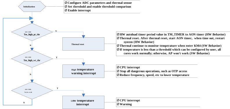
The operation flow is mainly divided into an initialization phase and a continuous monitoring phase. The system continuously compares the sensor output temperature ( ADC CODE ) with three predefined thresholds to adopt different software and hardware protection mechanisms. The specific flow is as follows:
Initialization Phase
After the system starts, it first enters the initialization flow. During this phase, the system executes the following operations sequentially:
Configure the relevant parameters of the Analog-to-Digital Converter (ADC).
Set temperature thresholds and enable the threshold comparison function.
Enable the temperature sensor module.
Enable interrupts to prepare for subsequent temperature warnings and protective actions.
Continuous Monitoring Phase
After initialization is complete, the system enters a continuous temperature threshold determination loop, sequentially performing the following three state detections according to priority:
Over-Temperature Protection Determination (ADC CODE >= tm_high_pt_thr)
The system first determines whether the sensor output temperature ( ADC CODE ) is greater than or equal to the over-temperature protection threshold ( tm_high_pt_thr ).
If the condition is met: Trigger a thermal reset.
Hardware behavior: The hardware automatically loads the timing period value in TM_TIMER into the AON timer. The AON timer is started after the thermal reset is executed, and the system is rebooted after the timer expires.
Software behavior: The system will continue to monitor the temperature after rebooting. If the temperature drops below the user-configured safe threshold, all cores will resume normal operation; otherwise, the Application Processor (AP) will remain in a halted state.
If the condition is not met: Proceed to the next level of determination.
High-Temperature Warning Determination (ADC CODE >= tm_high_wt_thr)
If a thermal reset is not triggered, the system then determines whether the temperature is greater than or equal to the high-temperature warning threshold ( tm_high_wt_thr ).
If the condition is met: Trigger a high-temperature warning interrupt. The system will issue an interrupt request to the CPU, and it is recommended that the user implement strategies such as lowering the main frequency or reducing the operating speed to achieve physical cooling of the system.
If the condition is not met: Proceed to the next level of determination.
Low-Temperature Warning Determination (ADC CODE <= tm_low_wt_thr)
If no high-temperature protection mechanisms are triggered, the system further determines whether the temperature is less than or equal to the low-temperature warning threshold ( tm_low_wt_thr ).
If the condition is met: Trigger a low-temperature warning interrupt, issue an interrupt to the CPU, and report the low-temperature warning.
If the condition is not met: The system performs no action and directly returns to the starting point of the monitoring loop to restart the next round of ADC CODE threshold determination.
The entire process loops repeatedly to ensure reliable operation of the system within the set safe temperature range.
Acquiring Temperature
Temperature values cannot be obtained directly; the following steps are required:
Select thermal (ch8) as the ADC conversion channel.
Start the ADC. The thermal conversion code will be stored in the ADC FIFO or the ch8 data register.
The software reads the data from the ADC FIFO or the ch8 data register and uses the following formula to convert the ADC code into a temperature value.
Temperature = 0.4964 * ADC CODE - 292.3
Interrupt
The thermal sensor supports the following interrupts:
High-temperature warning interrupt (tm_high_wt_thr): Generated when the thermal sensor detects that the temperature reaches or exceeds the high-temperature warning threshold. This interrupt is maskable and is disabled by default.
Low-temperature warning interrupt (tm_low_wt_thr): Generated when the thermal sensor detects that the temperature reaches or drops below the low-temperature warning threshold. This interrupt is maskable and is disabled by default.
Power-on Flow
The power-on flow of the thermal sensor can be described as the following figure.
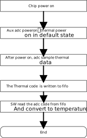
Power-on temperature is the first adc data in ADC FIFO.

