Functional Description
Interconnection Topology
SPI can be configured to operate in one of two modes: serial master or serial slave. SPI can connect to any serial master or serial slave peripheral device using the Motorola Serial Peripheral Interface. To connect to a serial master or serial slave peripheral device via SPI, the peripheral must have a Motorola Serial Peripheral Interface.
The serial protocol supported by SPI allows the selection of serial slaves:
Single slave: Connect the master’s slave select pin to the slave’s slave select pin.

Multiple slaves: Since the SPI master has only one slave select output (determined by the SPI hardware design), users should use GPIO to control multiple SPI slaves. Only one slave can be selected at a time.

Communication Format
There are four possible combinations of serial clock phase and clock polarity. The clock phase (SCPH) determines whether the serial transfer starts from the falling edge of the slave select signal or from the first edge of the serial clock. The clock polarity (SCPOL) configuration parameter determines whether the idle state of the serial clock is high or low. For correct data transmission, the SPI peripherals on both communicating sides must have the same serial clock phase (SCPH) and clock polarity (SCPOL) values.
When the configuration parameter SCPH = 0, data transmission starts from the falling edge of the slave select signal. The first data bit is captured by the master and slave peripherals on the first edge of the serial clock; therefore, valid data must already be present on the MOSI and MISO lines before the first serial clock edge arrives. The figure below shows the timing diagram of a single SPI data transfer when SCPH = 0, with serial clock waveforms for both SCPOL = 0 and SCPOL = 1 configuration parameters.
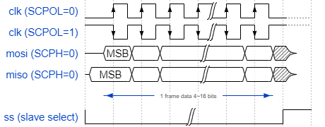
SPI Serial Format (SCPH = 0)
When SCPH = 0, during continuous data transfers, whether the slave select signal of the SPI master toggles before the next data frame can be configured through the SS_T field in the CTRLR0 register. Regardless of whether the master toggles the slave select signal during continuous data transfers, the SPI slave can communicate normally with the SPI master. The timing diagrams for SS toggling and SS non-toggling are shown below. The SS toggling feature is used for compatibility with different SPI devices.

SPI Serial Format Continuous Transfers (SCPH = 0, SS Toggling)
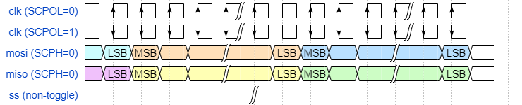
SPI Serial Format Continuous Transfers (SCPH = 0, SS Non-Toggling)
When the configuration parameter SCPH = 1, both master and slave peripherals begin transmitting data on the first serial clock edge after the slave select line is activated. The first data bit is captured on the second (trailing) serial clock edge. Data is propagated by the master and slave peripherals on the leading edge of the serial clock. During continuous data frame transfers, the slave select line can remain active low until the last bit of the last frame is captured. The figure below shows the timing diagram of the SPI format when SCPH = 1, with serial clock waveforms for both SCPOL = 0 and SCPOL = 1 configuration parameters.
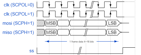
SPI Serial Format (SCPH = 1)
Continuous data frames are transferred in the same manner as a single frame, with the most significant bit (MSB) of the next frame immediately following the least significant bit (LSB) of the current frame. The slave select signal remains active throughout the entire transfer. The figure below shows the timing diagram of SPI continuous transfers when SCPH = 1.
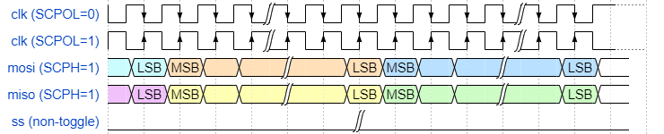
SPI Serial Format Continuous Transfers (SCPH = 1, SS Non-Toggling)

SPI Serial Format Continuous Transfers (SCPH = 1, SS Toggling)
Data Format
Data Frame Length
The SPI controller supports a configurable data frame length of 4 to 16 bits, set through the DFS field of the CTRLR0 register. The reset default value is 8 bits.
Regardless of the configured DFS value, valid data in the FIFO is always right-aligned, with the upper bits zero-padded. The transmit logic processes only the valid bits and ignores unused upper bits; the receive logic stores the serial input data into the receive FIFO in the same format.
Bit Order Swap
By default, the SPI controller transmits data on the serial line in MSB-first order. When LSB-first order is required, the bit order swap bits in the CTRLR0 register can be used to enable hardware-level automatic swapping on the transmit or receive channel. Swapping operates on a per-FIFO-entry (16-bit) basis, independently bit-reversing the high byte [15:8] and the low byte [7:0]. No software per-bit processing is needed.
The transmit channel is controlled by TXBITSWAP (CTRLR0 [22]), and the receive channel is controlled by RXBITSWAP (CTRLR0 [24]). The two are independent of each other and can be configured separately according to external device requirements. Setting a bit to 0 means no swap (MSB first), while setting it to 1 means swap (LSB first).
Taking DFS = 8 as an example, writing 0x00B1 (low byte 10110001) to DR:
Configuration |
Bit Order Processing |
Output Data |
|---|---|---|
|
No swap (MSB first) |
10110001 (0xB1) |
|
Bit swap (LSB first) |
10001101 (0x8D) |
Note
Since bit order swapping operates on a full 16-bit FIFO entry, it is recommended to enable this feature only when DFS = 8 or DFS = 16. For other DFS values, the valid data bits are not an integer multiple of 8 or 16, so the hardware zero-pads the upper bits. The zero-padded bits will be included in the swap, resulting in loss of valid data.
Byte Order Swap
The SPI controller supports separate byte order swap configuration for the transmit and receive channels. It swaps the high byte [15:8] and the low byte [7:0] of the 16-bit data in a FIFO entry. Byte order swap is disabled by default. When the byte order needs to be changed, the byte order swap bits in the CTRLR0 register can be used to enable hardware-level automatic swapping, without requiring software per-byte processing.
The transmit channel is controlled by TXBYTESWAP (CTRLR0 [21]), and the receive channel is controlled by RXBYTESWAP (CTRLR0 [23]). The two are independent of each other and can be configured separately according to external device requirements. Setting a bit to 0 means no swap (high byte first), while setting it to 1 means swap (low byte first).
Taking DFS = 16 as an example, writing 0xA569 (high byte 0xA5, low byte 0x69) to DR:
Configuration |
Byte Order Processing |
Output Data |
|---|---|---|
|
No swap (high byte first) |
0xA5 → 0x69 |
|
Bytes swapped (low byte first) |
0x69 → 0xA5 |
Note
Since byte order swapping operates on a full 16-bit FIFO entry, it is recommended to enable this feature only when DFS = 16. When DFS < 16, the upper region is zero-padded. After byte swapping, the zero byte will be swapped into the low position, resulting in corrupted valid data.
Clock Configuration
When SPI is configured as a master, the maximum frequency of the serial clock (sclk_out) is half the frequency of the SPI peripheral clock (ssi_clk). This allows the shift control logic to capture data on one clock edge of sclk_out and propagate data on the other edge, as shown in the figure below. The sclk_out signal line toggles only during active data transfers. At all other times, it remains inactive, as defined by the serial protocol under which it operates.
The frequency of sclk_out can be derived from the following formula:
Fsclk_out= Fssi_clk/SCKDV
SCKDV is a bit field in the programmable register BAUDR, and can be set to any even value from 0 to 65534. If SCKDV is 0, sclk_out is disabled. The maximum ratio of sclk_out to ssi_clk is shown in the figure below.

Maximum sclk_out/ssi_clk Ratio
The chip supports high-speed SPI slave. When SPI is configured as a slave, the maximum frequency of the serial clock (sclk_in) provided by the SPI master can be up to half the ssi_clk frequency.
The frequency ratio constraints between the serial clock (sclk_out/sclk_in) and the SPI peripheral clock (ssi_clk) are summarized as follows:
Master: Fssi_clk>= 2 x (maximum Fsclk_out)
Slave: Fssi_clk>= 2 x (maximum Fsclk_in)
The Fssi_clkof SPI0 and SPI1 are identical, supporting up to 100 MHz.
Note
Fssi_clkis affected by the PLL (Phase-Locked Loop) configuration during the Bootloader stage.
Transfer Mode
When transmitting data on the serial bus, the SPI master can operate in multiple modes as described below. The transfer mode (TMOD) is configured by writing to control register 0 (CTRLR0).
The following transfer modes apply only to the SPI master. The SPI slave always operates in full-duplex mode, as described in the Slave Mode section.
Full-Duplex Mode
When TMOD = 2'b00, both transmit and receive logic are active. Transmit data is popped from the transmit FIFO and sent to the target device via the MOSI line, while the target device returns data via the MISO line. Received data from the target device is shifted from the receive shift register into the receive FIFO at the end of each data frame.
Transmit Only Mode
When TMOD = 2'b01, received data is invalid and should not be stored in the receive FIFO. Transmit data is popped from the transmit FIFO and sent to the target device via the MOSI line, while the target device returns data via the MISO line. At the end of the data frame, the receive shift register does not load newly received data into the receive FIFO. Data in the receive shift register will be overwritten during the next transfer. When entering this mode, interrupts from the receive logic should be masked.
Receive Only Mode
When TMOD = 2'b10, transmit data is invalid. The MOSI output remains at a constant logic level during the transfer. Received data from the target device is shifted from the receive shift register into the receive FIFO at the end of each data frame. When entering this mode, interrupts from the transmit logic should be masked.
FIFO Management
Both the transmit and receive FIFO Buffers have a depth of 64. Since the serial specification defines the length of a single serial transfer (data frame) as 4 to 16 bits, the width is fixed at 16 bits. Each data entry in the FIFO Buffer contains one data frame.
Note
When SPI is disabled (SSI_EN = 0) or reset, the transmit and receive FIFO Buffers are cleared.
The transmit FIFO is loaded through APB write operations to the SPI data register (DR). Data is popped (removed) from the transmit FIFO by the shift control logic into the transmit shift register. When the number of entries in the FIFO is less than or equal to the FIFO threshold, the transmit FIFO generates a FIFO empty interrupt request (ssi_txe_intr). This threshold is set through the programmable register TXFTLR, which determines the FIFO entry level at which the interrupt is generated. This threshold can provide the processor with an early indication that the transmit FIFO is about to become empty. If an attempt is made to write data to a full transmit FIFO, a transmit FIFO overflow interrupt (ssi_txo_intr) is generated.
Data is popped from the receive FIFO through APB read operations to the SPI data register (DR). The receive FIFO is loaded by the receive shift register via the shift control logic. When the number of entries in the FIFO is greater than or equal to the FIFO threshold plus 1, the receive FIFO generates a FIFO full interrupt request (ssi_rxf_intr). This threshold is set through the programmable register RXFTLR, which determines the FIFO entry level at which the interrupt is generated.
This threshold can provide the processor with an early indication that the receive FIFO is about to become full. When the receive shift logic attempts to load data into a full receive FIFO, a receive FIFO overflow interrupt (ssi_rxo_intr) is generated, and the newly received data is lost. If an attempt is made to read from an empty receive FIFO, a receive FIFO underflow interrupt (ssi_rxu_intr) is generated. This alerts the processor that the read data is invalid.
FIFO Slice
Not supported.
Not supported.
Not supported.
Not supported.
Not supported.
Not supported.
Not supported.
Not supported.
Interrupt Handling
SPI supports combined interrupt requests and individual interrupt requests, and each interrupt can be masked. The combined interrupt request is the OR result of all other SPI interrupts after masking. System designers can choose to route individual interrupt requests or only the combined interrupt request to the interrupt controller.
Interrupt Description
The trigger conditions and clearing methods for each interrupt are described as follows:
Transmit FIFO Empty Interrupt (
ssi_txe_intr) – Asserted when the number of transmit FIFO entries is less than or equal to its threshold, requiring service to prevent underflow. This threshold is set through a software-programmable register to determine the transmit FIFO entry level at which the interrupt is generated. This interrupt is automatically cleared by hardware when data is written to the transmit FIFO and raises it above the threshold level.Transmit FIFO Overflow Interrupt (
ssi_txo_intr) – Asserted when an APB access attempts to write data to a full transmit FIFO. When asserted, write data from the APB is discarded. This interrupt remains asserted until the Transmit FIFO Overflow Interrupt Clear Register (TXOICR) is read.Receive FIFO Underflow Interrupt (
ssi_rxu_intr) – Asserted when an APB access attempts to read data from an empty receive FIFO. When asserted, the data read back from the receive FIFO is zero. This interrupt remains asserted until the Receive FIFO Underflow Interrupt Clear Register (RXUICR) is read.Receive FIFO Overflow Interrupt (
ssi_rxo_intr) – Asserted when the receive logic attempts to put data into the receive FIFO when it is already full. When asserted, the newly received data is discarded. This interrupt remains asserted until the Receive FIFO Overflow Interrupt Clear Register (RXOICR) is read.Receive FIFO Full Interrupt (
ssi_rxf_intr) – Asserted when the number of receive FIFO entries is greater than or equal to its threshold plus 1, requiring service to prevent overflow. This threshold is set through a software-programmable register to determine the receive FIFO entry level at which the interrupt is generated. This interrupt is automatically cleared by hardware when data is read from the receive FIFO and drops it below the threshold level.Frame Alignment Error Interrupt (
ssi_fae_intr) – Valid only when SPI is configured as a serial slave device. This interrupt is asserted when the received data frame length does not match the DFS (Data Frame Size) setting in CTRLR0. This interrupt remains asserted until the Frame Alignment Error Interrupt Clear Register (MSTICR_FAEICR) is read.Multi-Master Contention Interrupt (
ssi_mst_intr) – Not supported at this time.Transmit FIFO Underflow Interrupt (
ssi_txu_intr) – Valid only when SPI is configured as a serial slave device. This interrupt is asserted when the transmit logic attempts to read data from an empty transmit FIFO. When asserted, the data transmitted by the slave device is invalid. This interrupt remains asserted until the Transmit FIFO Underflow Interrupt Clear Register (TXUICR) is read.SS_N Rising Edge Detection Interrupt (
ssi_ssr_intr) – Valid only when SPI is configured as a serial slave device. This interrupt is asserted when an SS_N rising edge is detected. This interrupt remains asserted until the SS_N Rising Edge Detection Interrupt Clear Register (SSRICR) is read.
Not supported.
Not supported.
Not supported.
Not supported.
Not supported.
Not supported.
Not supported.
Not supported.
Interrupt Masking
The SPI Interrupt Mask Register (SPI_IMR) controls whether each interrupt source is masked. Each mask bit corresponds to an interrupt source: setting it to 1 means unmasked (interrupt enabled), and setting it to 0 means masked (interrupt disabled). The mask bits are defined as follows:
Transmit FIFO Empty Interrupt Mask (SPI_BIT_TXEIM) – Controls the
ssi_txe_intrinterrupt.Transmit FIFO Overflow Interrupt Mask (SPI_BIT_TXOIM) – Controls the
ssi_txo_intrinterrupt.Receive FIFO Underflow Interrupt Mask (SPI_BIT_RXUIM) – Controls the
ssi_rxu_intrinterrupt.Receive FIFO Overflow Interrupt Mask (SPI_BIT_RXOIM) – Controls the
ssi_rxo_intrinterrupt.Receive FIFO Full Interrupt Mask (SPI_BIT_RXFIM) – Controls the
ssi_rxf_intrinterrupt.Multi-Master Contention/Frame Alignment Error Interrupt Mask (SPI_BIT_MSTIM_FAEIM) – When SPI is configured as master, controls the
ssi_mst_intrinterrupt (not supported at this time); when SPI is configured as slave, controls thessi_fae_intrinterrupt.Transmit FIFO Underflow Interrupt Mask (SPI_BIT_TXUIM) – Valid only when SPI is configured as slave, controls the
ssi_txu_intrinterrupt.SS_N Rising Edge Detection Interrupt Mask (SPI_BIT_SSRIM) – Valid only when SPI is configured as slave, controls the
ssi_ssr_intrinterrupt.
Not supported.
Not supported.
Not supported.
Not supported.
Not supported.
Not supported.
Not supported.
Not supported.
Role Selection
The chip uses two separate sets of circuits when operating as an SPI master or SPI slave. Therefore, the user must configure the SPI role before initializing the device. The relevant register descriptions are as follows.
REG_LSYSPLAT_CTRL
Size: 32
Address: 0x41008230
Read/write access: R/W
Bit |
Symbol |
Access |
INI |
Description |
|---|---|---|---|---|
27 |
SPI1_MST |
R/W |
0h |
|
26 |
SPI0_MST |
R/W |
0h |
|
The chip uses two separate sets of circuits when operating as an SPI master or SPI slave. Therefore, the user must configure the SPI role before initializing the device. The relevant register descriptions are as follows.
REG_LSYSPLAT_CTRL
Size: 32
Address: 0x4100C230
Read/write access: R/W
Bit |
Symbol |
Access |
INI |
Description |
|---|---|---|---|---|
27 |
SPI1_MST |
R/W |
0h |
|
26 |
SPI0_MST |
R/W |
0h |
|
The chip uses two separate sets of circuits when operating as an SPI master or SPI slave. Therefore, the user must configure the SPI role before initializing the device. The relevant register descriptions are as follows.
REG_LSYSPLAT_CTRL
Size: 32
Address: 0x4100C230
Read/write access: R/W
Bit |
Symbol |
Access |
INI |
Description |
|---|---|---|---|---|
27 |
SPI1_MST |
R/W |
0h |
|
26 |
SPI0_MST |
R/W |
0h |
|
The chip uses two separate sets of circuits when operating as an SPI master or SPI slave. Therefore, the user must configure the SPI role before initializing the device. The relevant register descriptions are as follows.
REG_LSYSPLAT_CTRL
Size: 32
Address: 0x4100C230
Read/write access: R/W
Bit |
Symbol |
Access |
INI |
Description |
|---|---|---|---|---|
27 |
SPI1_MST |
R/W |
0h |
|
26 |
SPI0_MST |
R/W |
0h |
|
The chip uses two separate sets of circuits when operating as an SPI master or SPI slave. Therefore, the user must configure the SPI role before initializing the device. The relevant register descriptions are as follows.
REG_LSYSPLAT_CTRL
Size: 32
Address: 0x4100C230
Read/write access: R/W
Bit |
Symbol |
Access |
INI |
Description |
|---|---|---|---|---|
27 |
SPI1_MST |
R/W |
0h |
|
26 |
SPI0_MST |
R/W |
0h |
|
The chip uses two separate sets of circuits when operating as an SPI master or SPI slave. Therefore, the user must configure the SPI role before initializing the device. The relevant register descriptions are as follows.
REG_HSYSHPLAT_CTRL
Size: 32
Address: 0x41000030
Read/write access: R/W
Bit |
Symbol |
Access |
INI |
Description |
|---|---|---|---|---|
26 |
SPI1_MST |
R/W |
0h |
|
25 |
SPI0_MST |
R/W |
0h |
|
The chip uses two separate sets of circuits when operating as an SPI master or SPI slave. Therefore, the user must configure the SPI role before initializing the device. The relevant register descriptions are as follows.
REG_LSYSPLAT_CTRL
Size: 32
Address: 0x4080A2A0
Read/write access: R/W
Bit |
Symbol |
Access |
INI |
Description |
|---|---|---|---|---|
27 |
SPI1_MST |
R/W |
0h |
|
26 |
SPI0_MST |
R/W |
0h |
|
The chip uses two separate sets of circuits when operating as an SPI master or SPI slave. Therefore, the user must configure the SPI role before initializing the device. The relevant register descriptions are as follows.
REG_LSYSPLAT_CTRL
Size: 32
Address: 0x408012A0
Read/write access: R/W
Bit |
Symbol |
Access |
INI |
Description |
|---|---|---|---|---|
27 |
SPI1_MST |
R/W |
0h |
|
26 |
SPI0_MST |
R/W |
0h |
|
Master Mode
This mode implements serial communication with serial slave peripherals. When configured as a serial master, the SPI initiates and controls all serial transfers. This figure shows an example of the SPI configured as a serial master, with all other devices on the serial bus controlled by GPIO as slave select signals.
The serial clock generated and controlled by the SPI master is output through the sclk_out line. When the SPI is disabled (SSI_EN = 0), no serial transfers occur, and sclk_out remains inactive.
Transfer Control
Data transfers are initiated and controlled by the serial master, involving start, stop, and status phases.
Start
Before a transfer begins, the slave select signal must be driven low: if using the built-in slave select signal (hardware CS), it is automatically driven low by hardware; if using a GPIO to emulate the slave select signal (software CS), the user must manually control the GPIO to drive it low.
A transfer starts when three conditions are met: the SPI is enabled (SSI_EN=1), there is at least one valid data entry in the transmit FIFO, and a serial slave is selected. To ensure continuous transfer integrity, at least two data entries can be pre-written to the transmit FIFO before enabling the slave, so that the transfer actually begins only after data frames are present in the FIFO.
For receive-only mode (TMOD = 2'b10), the startup method differs slightly: dummy data must be written to the transmit FIFO when selecting the slave to trigger the serial clock. During the transfer, the MOSI output maintains a constant logic level, and the transmit FIFO is popped only once at the start, after which it can remain empty.
The transmit FIFO threshold (TXFTLR) can generate an early interrupt (ssi_txe_intr) when the number of FIFO entries is less than or equal to the threshold, notifying the processor that the transmit FIFO is about to become empty. When using DMA, the transmit data level (DMATDLR) can issue an early request (dma_tx_req) to the DMA controller to replenish data in time and maintain continuous transfers.
The receive FIFO threshold (RXFTLR) can provide an early indication that the FIFO is about to become full when the number of entries is greater than or equal to the threshold plus one. When using DMA, the receive data level (DMARDLR) can issue an early request (dma_rx_req) to the DMA controller to read data in time and prevent overflow.
Stop
The stop conditions under different transfer modes are as follows:
In full-duplex mode and transmit-only mode (TMOD = 2'b00 or TMOD = 2'b01), the shift control logic terminates the transfer when the transmit FIFO is empty. Therefore, during continuous data transfers, ensure that the transmit FIFO does not become empty before all data has been transferred.
In receive-only mode (TMOD = 2'b10), the transfer end is determined by the number of data frames (NDF) field in Control Register 1 (CTRLR1). When the number of received frames equals NDF + 1, the receive logic terminates the transfer. For example, to receive 24 frames, program NDF to 23. In this mode, the transmit FIFO does not need to be continuously serviced during the transfer, saving APB bandwidth, but data should be read promptly each time the receive FIFO generates a full interrupt to prevent overflow.
After the transfer completes, the slave select signal must be driven high: if using hardware CS, it is automatically driven high by hardware; if using software CS, the user must manually control the GPIO to drive it high.
Status
During SPI transfers, the busy flag (BUSY) in the status register (SPI_SR) indicates the current transfer status:
Set (1): Indicates the SPI is actively transferring data
Clear (0): Indicates the SPI is idle
Before initiating the next serial transfer, the BUSY flag must be checked, and software must wait until it is cleared.
Chip Select Control
Not supported.
Not supported.
Not supported.
Not supported.
Not supported.
Not supported.
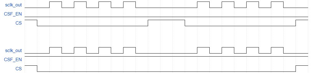
In some scenarios, interrupts may not be serviced in time to fill the TX FIFO, causing it to become empty. Therefore, the CSF_EN bit in register CTRLR0 allows the SPI master to force the slave select signal to remain low until the entire transfer is complete. Additionally, during a transfer that has not yet completed, when the TX FIFO is empty, the SPI master keeps the CS signal low and pauses the transfer (without sending the sclk clock signal).
When the CSF_EN bit is enabled, the SPI master calculates the number of data bits to be transmitted. The calculation is the Data Frame Length (CTRLR0 [3:0]) multiplied by the Number of Data Frames (CTRLR1 [15:0]). Subsequently, the SPI master forces the slave select signal to remain low during the transfer. The SPI master releases this force control only when the number of transmitted data bits reaches the calculated value. An example of CSF_EN usage is shown below.
In some scenarios, interrupts may not be serviced in time to fill the TX FIFO, causing it to become empty. Therefore, the CSF_EN bit in register CTRLR0 allows the SPI master to force the slave select signal to remain low until the entire transfer is complete. Additionally, during a transfer that has not yet completed, when the TX FIFO is empty, the SPI master keeps the CS signal low and pauses the transfer (without sending the sclk clock signal).
When the CSF_EN bit is enabled, the SPI master calculates the number of data bits to be transmitted. The calculation is the Data Frame Length (CTRLR0 [3:0]) multiplied by the Number of Data Frames (CTRLR1 [15:0]). Subsequently, the SPI master forces the slave select signal to remain low during the transfer. The SPI master releases this force control only when the number of transmitted data bits reaches the calculated value. An example of CSF_EN usage is shown below.
Receive Delayed Sampling
The slave uses the clock signal from the master as a strobe signal to drive data onto the MISO line. Due to round-trip routing delays in the clock signal, the slave’s data output may appear delayed from the master’s perspective, deviating from the normal sampling time. When the SPI is configured as a master, additional logic can be included to delay the default sampling time of the MISO signal, which helps increase the maximum achievable frequency on the serial bus.
The figure below shows an example of how routing delays on the MOSI signal can cause the master to sample incorrect MISO values at the default sampling time. The blue arrows represent the routing delays between the master and slave; the red lines represent the sampling delay from when the slave receives the clock to when it drives data output on the MISO line.
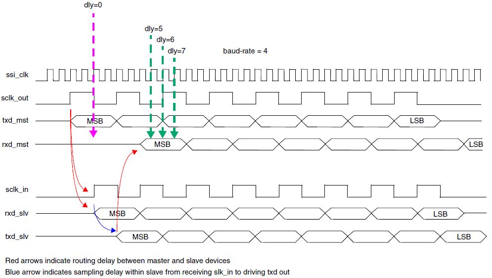
Effects of round-trip routing delays on the clock signal
When the receive data line (RXD) sampling delay logic is included, the delay value can be dynamically programmed to offset the sampling time of the rxd signal from the default by a number of ssi_clk cycles.
The sampling delay logic has a resolution of one ssi_clk cycle. Software can “calibrate” the serial bus by writing a loop that continuously reads from the slave and increments the master RXD sampling delay value until the master receives correct data.
Note
The maximum number of ssi_clk cycles available for delaying the rxd input sampling is 4. If the programmed delay value exceeds this maximum, zero (0) delay will be applied to the rxd sampling.
Slave Mode
This mode enables serial communication with an SPI master peripheral. When the SPI is configured as a slave device, all serial transfers are initiated and controlled by the serial bus master.
The SPI slave can only operate in transmit-and-receive mode. That is, the TMOD field in the CTRLR0 register has no effect on the SPI slave. If the device is not expected to respond with data, the slave output can be disabled through the SLV_OE bit in CTRLR0.
When the SPI slave is selected during configuration, it outputs MISO data onto the serial bus. All data transfers in and out of the SPI slave are controlled by the serial clock line (sclk_in), which is driven by the SPI master. Data is propagated from the SPI slave on one edge of the serial clock line and sampled on the opposite edge.
When the SPI slave is not selected, it must not interfere with data transfers between the SPI master and other SPI slave devices, and its MISO output is buffered, presenting a high-impedance drive on the MISO line of the SPI master.
The serial clock that regulates data transfers is generated by the SPI master and input to the SPI slave via sclk_in. The slave remains idle until selected by the bus master. When not actively transferring data, the slave must keep its MISO line in a high-impedance state to avoid interfering with serial transfers to and from other slave devices. As long as the slave remains selected, it continues to transfer data to and from the master.
Transfer Control
If the SPI slave is to transmit data to the master, it must ensure that data is already present in the transmit FIFO before the SPI master initiates a transfer. If the master initiates a transfer to the SPI slave when there is no data in the transmit FIFO, an error flag (TXE) is set in the SPI status register, and the previously transmitted data frame is retransmitted on MISO. For continuous data transfers, it must be ensured that the transmit FIFO does not become empty before all data transfers are complete. The transmit FIFO threshold level register (TXFTLR) can be used to generate an early interrupt (ssi_txe_intr) to the processor, indicating that the transmit FIFO is about to become empty. When using the DMA controller for APB access, the DMA transmit data level register (DMATDLR) can be used to generate an early request (dma_tx_req) to the DMA controller, indicating that the transmit FIFO is about to become empty. The FIFO can then be refilled with data to continue the serial transfer.
The receive FIFO should be read each time a FIFO full interrupt request is generated by the receive FIFO to prevent overflow. The receive FIFO threshold level register (RXFTLR) can be used to provide an early indication that the receive FIFO is about to become full. When using the DMA controller for APB access, the DMA receive data level register (DMARDLR) can be used to generate an early request (dma_rx_req) to the DMA controller, indicating that the receive FIFO is about to become full.
TX Data Update Phase
Not supported.
Not supported.
Not supported.
Not supported.
Not supported.
Not supported.
Not supported.
Not supported.
DMA Support
SPI has an optional built-in DMA capability that can be selected during configuration. It provides a handshake interface with the DMA controller for requesting and controlling data transfers. The APB bus is used to perform data transfers to and from the DMA.
SPI uses two DMA channels: one for transmitting data and one for receiving data. SPI has the following DMA registers:
DMACR: Control register used to enable DMA operations.
DMATDLR: Transmit threshold register used to set the transmit FIFO data level threshold that triggers a DMA request.
DMARDLR: Receive threshold register used to set the receive FIFO data level threshold that triggers a DMA request.
To enable the DMA controller interface on SPI, the DMA Control Register (DMACR) must be written. Writing '1' to the TDMAE bit field of DMACR enables the SPI transmit handshake interface. Writing '1' to the RDMAE bit field of DMACR enables the SPI receive handshake interface.
Transmit Data Threshold and Transmit FIFO Underflow
During SPI serial transfer, a transmit FIFO request is sent to the DMA controller whenever the number of data entries in the transmit FIFO is less than or equal to the value of the DMA Transmit Data Level Register (DMATDLR). This value is referred to as the transmit data threshold. The DMA controller responds by writing a burst of data into the transmit FIFO.
Data should be fetched from the DMA frequently enough to ensure that the transmit FIFO can sustain continuous serial transfer; that is, when the FIFO is about to become empty, another DMA request should be triggered in time. Otherwise, the FIFO will experience data starvation (underflow). To prevent this, the user must set the threshold correctly.
Receive Data Threshold and Receive FIFO Overflow
During SPI serial transfer, a receive FIFO request is sent to the DMA controller whenever the number of data entries in the receive FIFO reaches or exceeds the value of the DMA Receive Data Level Register plus 1, that is, DMARDLR + 1. This value is referred to as the receive data threshold. The DMA controller responds by fetching a burst of data from the receive FIFO.
The DMA should fetch data frequently enough to ensure that the receive FIFO can continuously accept incoming serial data; that is, when the FIFO is about to become full, another DMA transfer should be requested in time. Otherwise, the FIFO will experience data overflow. To prevent this, the user must set the threshold correctly.

