Introduction
The IR module is used to process infrared signals with carrier frequencies below 500kHz. It supports both transmit (Tx) and receive (Rx) modes, operating in half-duplex.
In the transmit direction, the IR module has built-in hardware modulation, which directly performs carrier modulation and drives the IR Tx output. In the receive direction, the IR module can measure the pulse width periods of consecutive high and low level signals and write the measurement results into the Rx FIFO in sequence, so that software can parse the infrared waveform sequence and perform further processing. In addition, the receive front end supports two hardware connection types: IR Diode and IR Receiver Module. Users can choose between them based on their application scenarios.
Features
Supports customizable transmit carrier frequency, configurable range: 25kHz to 500kHz
Supports customizable transmit carrier duty cycle
Receive front-end supports two hardware input types: IR diode and IR receiver module
32 × 4-byte Tx FIFO
32 × 4-byte Rx FIFO
Supports half-duplex operation mode
Block Diagram
The IR module block diagram is shown below:
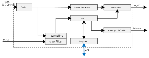
Scaler: Divides the system clock (SCLK) to generate the Tx carrier frequency or Rx sampling frequency.
Carrier Generator: Generates Tx carrier symbols and supports flexible duty cycle configuration.
Modulation: Modulates space symbols into carrier symbols.
Glitch Filter: Filters out glitch interference from the input signal at the receiving end.
FIFO
Tx FIFO: Stores Tx carrier symbol count values and data states.
Rx FIFO: Buffers data received from the IR input pin for software to read and process.
Interrupt Control: Generates interrupt events to the processor.
Register: Used to configure IR module parameters.