Functional Description
Working Principle
To simplify the IR signal model, an IR signal is divided into several symbols. Symbols are classified into two types: a signal that contains several carrier clock cycles within a specific period is called a Carrier Symbol; a signal that maintains a continuous high or low level within a specific period is called a Space Symbol. The carrier symbol corresponds to the actual signal transmitted in the air, while the space symbol corresponds to the baseband signal before modulation or after demodulation. The IR signal model is shown in the following figure.

Transmit Mode
The operating mode is selected by the IR_MODE_SEL bit field. Setting it to 0 enters Tx mode. In Tx mode, software first configures the modulation parameters to generate a fixed-frequency carrier, and then writes the durations of carrier symbols and space symbols into the Tx FIFO in sequence. The Tx module automatically performs modulation and transmits the IR signal. The IR Tx flow is shown in the following figure.

Receive Mode
Setting the IR_MODE_SEL bit field to 1 enters Rx mode. In Rx mode, the IR module uses the sampling clock as a reference to measure the pulse width of continuous high and low level signals in the input, and writes the measurement results sequentially into the Rx FIFO for software to parse the waveform. The IR module supports two types of Rx front end:
IR receiver module: The carrier has already been filtered out by the front-end module, and the input signal is a clean baseband signal. The IR module directly captures space symbols, and software only needs to decode them.
IR diode: The input signal still carries the carrier. The IR module captures carrier symbols, and software needs to demodulate them before decoding, which incurs additional CPU overhead.
The IR Rx flow is shown in the following figure.

Scaler
The scaler is the core clock processing unit of the IR module. It takes SCLK as input and generates the internal clocks required by the IR module through programmable division. By configuring the IR_CLK_DIV bit field (12 bits) of the IR_CLK_DIV register, the division factor can be flexibly set: divided clock frequency = SCLK / (IR_CLK_DIV + 1).
Tx Mode
In Tx mode, the scaler output clock is the carrier frequency. The carrier generator uses this clock to produce carrier symbols with an adjustable duty cycle for driving IR transmission.
For example, when SCLK = 100MHz and the target carrier frequency is 455kHz,
IR_CLK_DIV = (100M / 455k) - 1.Rx Mode
In Rx mode, the scaler output clock is the sampling clock, which Rx uses to count the duration of each input level. For the count value format and conversion, see Rx FIFO Format.
The input clock (SCLK) frequency of the IR module varies by chip:
The default clock frequency is 40MHz.
The default clock frequency is 100MHz.
The default clock frequency is 40MHz.
The default clock frequency is 40MHz.
Transmit Mode
FIFO Format
Before transmission, IR data must be converted to the format defined by the IR Tx FIFO register and then written to it. The Tx FIFO register is 32 bits wide, and its bit fields are defined as follows:
bit[31] is the data type flag. 1: with carrier; 0: without carrier.
bit[30] is the data end flag. 1: last packet of the current transmission; 0: normal packet.
bit[29:28] is the Tx compensation mode, which determines the counting unit of bit[27:0]. 00: carrier period Tcarrier (no compensation); 11: compensation clock period Tcomp. See Compensation Mechanism for details.
bit[27:0] is the number of carrier cycles.
Let fcarrier represent the carrier frequency (in kHz), and Tduration represent the duration of a carrier symbol or space symbol (in μs). Then:
bit[27:0] = fcarrier × Tduration / 1000
FIFO Filling
Taking the NEC protocol as an example, the carrier frequency is 38kHz. The NEC format is shown in the figure below, consisting of 2 start symbols, 64 data symbols, and 1 stop symbol.
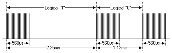
To transmit logic ‘1’, two words must be written to the Tx FIFO register:
First word: bit[31] = 1, bit[30] = 0, bit[27:0] = 38 × 560 / 1000 = 21.
Second word: bit[31] = 0, bit[30] = 0, bit[27:0] = 38 × (2250 - 560) / 1000 = 64.
To transmit logic ‘0’, two words must be written to the Tx FIFO register:
First word: bit[31] = 1, bit[30] = 0, bit[27:0] = 38 × 560 / 1000 = 21.
Second word: bit[31] = 0, bit[30] = 0, bit[27:0] = 38 × (1120 - 560) / 1000 = 21.
Finally, a stop symbol must be sent, with bit[30] set to 1 to indicate the end of the current transmission.
Compensation Mechanism
In most application scenarios, the compensation mechanism does not need to be enabled. If precision is not a concern, this section can be skipped.
The Tx waveform consists of several carrier symbols and space symbols. Software calculates the duration of each symbol based on protocol specifications (e.g., NEC), but the duration of a space symbol is generally not an integer multiple of the carrier period. Without compensation, the error accumulates across symbols. To address this, IR Tx introduces a compensation mechanism to reduce the error.
Taking the NEC application as an example, the following figure shows the Tx NEC waveform with fcarrier = 38kHz, duty = 1/3, and a system clock of 100MHz.

Tx NEC waveform
For a 38kHz carrier frequency:
Tcarrier = 1 / fcarrier = 1 / 38k = 26.31μs
Tcarrier_duty = Tcarrier × duty = 8.77μs
The compensation frequency is determined by the TX_COMPE_DIV bit field: fcomp = SCLK / (TX_COMPE_DIV + 1). In this example, the system clock is 100MHz and TX_COMPE_DIV is set to 99, so fcomp = 1MHz, and therefore:
Tcomp = 1 / fcomp = 1μs
The waveform is divided into four symbols: a 560μs carrier symbol, a 1690μs space symbol (2250μs - 560μs), a 560μs carrier symbol, and a 560μs space symbol (1120μs - 560μs). Comparing the two calculation methods below shows that the accuracy is significantly improved when using the compensation mechanism.
Item |
Normal Tx ( |
Tx Compensation ( |
|---|---|---|
1st cycle |
560μs ≈ 21 × 26.31 + 8.77 = 561.26μs |
560μs ≈ 21 × 26.31 + 8.77 = 561.26μs |
2nd cycle |
1690μs ≈ 64 × 26.31 + (26.31 - 8.77) = 1701.38μs |
1690μs ≈ (26.31 - 8.77) + 1673 × 1 = 1690.54μs |
3rd cycle |
560μs ≈ 21 × 26.31 + 8.77 = 561.26μs |
560μs ≈ 21 × 26.31 + 8.77 = 561.26μs |
4th cycle |
560μs ≈ 21 × 26.31 + (26.31 - 8.77) = 570.05μs |
560μs ≈ (26.31 - 8.77) + 543 × 1 = 560.54μs |
Tx FIFO data value |
0x80000015, 0x00000040; 0x80000015, 0x00000015 |
0x80000015, 0x30000689; 0x80000015, 0x3000021F |
Note
The compensation mechanism only applies to space symbols.
Compensation modes
IR_TX_COMPENSATION = 1andIR_TX_COMPENSATION = 2are not recommended. If compensation is needed, useIR_TX_COMPENSATION = 3mode.If IR_TX_DE_INVERSE is enabled, ensure that TX_COMPE_DIV is no less than the Tx duty count value, i.e., the IR_TX_DUTY_NUM bit field.
Receive Mode
FIFO Format
When receiving IR data, data must be read from the Rx FIFO register. The Rx FIFO register is 32 bits wide, with bit definitions as follows:
bit[31] indicates the data level. 1: high level; 0: low level.
bit[30:0] stores the received data, representing the level duration in number of sampling periods.
Let fsampling denote the sampling frequency (in kHz), and Tlevel denote the duration of the corresponding high/low level (in μs). Then:
Tlevel= bit[30:0] / fsampling× 1000
For example, with a 10MHz sampling clock (fsampling = 10000kHz), the count value 0x800000FF has bit[31] = 1 and bit[30:0] = 255, indicating a high level lasting 255 / 10000 × 1000 = 25.5μs.
Software can further parse the IR protocol and extract the required information based on Tlevel.
Receive Start
Both automatic start and manual start are supported, selected through the IR_RX_START_MODE bit field.
Automatic Start
Set IR_RX_START_MODE = 1 to enter automatic receive mode. In this mode, when the Rx input signal meets the preset trigger condition, the hardware automatically starts receiving. The trigger type is configured through the IR_RX_TRIGGER_MODE bit field:
Value |
Trigger Type |
Description |
|---|---|---|
00 |
IR_RX_FALL_EDGE |
Triggered when a falling edge (high level to low level) is detected |
01 |
IR_RX_RISING_EDGE |
Triggered when a rising edge (low level to high level) is detected |
10 |
IR_RX_DOUBLE_EDGE |
Triggered when any level transition (rising edge or falling edge) is detected |
After the Rx module is enabled, the hardware automatically waits for the trigger condition without software intervention.
Manual Start
Set IR_RX_START_MODE = 0 to enter manual receive mode. In this mode, software starts receiving by writing 1 to the IR_RX_MAN_START register, which is suitable for scenarios requiring precise control over the receive start point.
Receive Termination
The Rx module determines receive termination through a counter threshold interrupt. When the duration of a level in the input signal reaches the preset threshold, the IR_RX_CNT_THR_INT interrupt is triggered, indicating the end of a complete IR reception. The termination condition is configured through the bit fields in the following table:
Bit Field |
Description |
|---|---|
IR_RX_CNT_THR_TRIGGER_LV |
Termination level type. 0: trigger the interrupt when the low-level duration ≥ threshold; 1: trigger the interrupt when the high-level duration ≥ threshold |
IR_RX_CNT_THR |
31-bit count threshold, expressed in sampling periods, the same unit as the count value in the Rx FIFO |
IR_RX_CNT_THR_INT_EN |
Interrupt enable bit. This bit must be set to 1 for an interrupt request to be generated when the termination condition is met |
Note
The threshold should be configured according to the characteristics of the IR signal in the application scenario. The interval between two IR data frames is typically longer than the duration of any single level within a transmission, so setting this interval as the threshold reliably distinguishes data frames.
Glitch Filter
The IR Rx input has a built-in glitch filter that can filter out narrow pulse interference before sampling. The filter width is configured through the IR_RX_FILTER_STAGETX bit field. The filter width mappings for each chip are as follows:
Available filter widths: 50ns, 75ns, 100ns, 125ns, 150ns, 175ns, 200ns, 225ns.
Available filter widths: 20ns, 30ns, 40ns, 50ns, 60ns, 70ns, 80ns, 90ns.
Available filter widths: 50ns, 75ns, 100ns, 125ns, 150ns, 175ns, 200ns, 225ns.
Available filter widths: 50ns, 75ns, 100ns, 125ns, 150ns, 175ns, 200ns, 225ns.
Interrupt
The interrupt flags supported in each mode are listed in the table below. Each interrupt source can be enabled, masked, and cleared via *_INT_EN, *_INT_MASK, and *_INT_CLR respectively, and its status can be read via *_INT_STATUS.
Mode |
Interrupt Flag |
Description |
|---|---|---|
Tx Mode |
IR_TX_FIFO_OVER_INT |
This interrupt is triggered when data is written to Tx FIFO while it is already full. |
IR_TX_FIFO_LEVEL_INT |
This interrupt is triggered when Tx FIFO usage is less than or equal to the threshold. |
|
IR_TX_FIFO_EMPTY_INT |
This interrupt is triggered when Tx FIFO usage drops from 1 to 0 (i.e., FIFO is empty). |
|
Rx Mode |
IR_RX_FIFO_ERROR_INT |
This interrupt is triggered when data is read from Rx FIFO while it is empty. |
IR_RX_CNT_THR_INT |
This interrupt is triggered when the input level duration exceeds the Rx counter threshold. |
|
IR_RX_CNT_OF_INT |
This interrupt is triggered when the Rx counter overflows without triggering IR_RX_CNT_THR_INT. |
|
IR_RX_FIFO_OF_INT |
This interrupt is triggered when new data is received from the IR input pin while Rx FIFO is already full. |
|
IR_RX_FIFO_LEVEL_INT |
This interrupt is triggered when Rx FIFO usage is greater than or equal to the threshold. |
|
IR_RX_FIFO_FULL_INT |
This interrupt is triggered when Rx FIFO becomes full. |

