Introduction
The I2C bus interface handles communications between the chip and the serial I2C bus. It controls all I2C bus-specific sequencing, protocol, arbitration and timing. The design of I2C aims on sensor hub application in low-power or battery-powered productions. Essential features of I2C bus protocol should be provided for acquiring or controlling external sensor data.
Features
The I2C has the following features:
Two-wire I2C serial interface – a serial data line (SDA) and a serial clock (SCL)
Three speed modes:
Standard Speed (SS), up to 100kbps
Fast Speed (FS), up to 400kbps
High Speed (HS), up to 3.4Mbps
I2C interface: x2
Operation mode:
Polling
Interrupt
DMA
I2C interface: x2
Operation mode:
Polling
Interrupt
I2C interface: x2
Operation mode:
Polling
Interrupt
I2C interface: x2
Operation mode:
Polling
Interrupt
I2C interface: x2
Operation mode:
Polling
Interrupt
I2C interface: x3
Operation mode:
Polling
Interrupt
I2C interface: x2
Operation mode:
Polling
Interrupt
DMA
I2C interface: x2
Operation mode:
Polling
Interrupt
DMA
Master or Slave I2C operation
Transmitter or Receiver
Transmit and receive FIFOs with depth of 16 and width of 12-bit
Multi-master ability including bus arbitration scheme
Clock stretch in master/slave mode
7-bit or 10-bit addressing mode, 7-bit or 10-bit combined format transfer
Manual START/RESTART/STOP bit control
Supports General Call, NULL DATA, START BYTE transfer protocol
Component parameters for configurable software driver support (programmable SDA hold time, slave address, SCL duty cycle, etc.)
Filter to eliminate the glitches on the signal of SDA and SCL, programmable digital noise filter
Status flags (Bus busy flag, activity flag, FIFO status flag, etc.) and Error flags (arbitration lost, acknowledge failure, etc.)
Slave Mode Dual Own Address
Slave 1 supports 7-bit or 10-bit address mode
Slave 2 only supports 7-bit address mode
Block Diagram
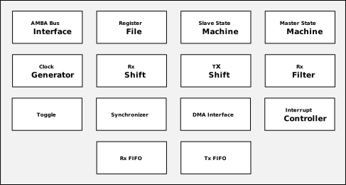
The block diagram of I2C is illustrated below. The following defines the file names and functions of the blocks.
AMBA Bus Interface: Receives access signals from the on-chip APB bus and maps them to an internal generic register interface, decoupling the bus protocol from the register file and improving module portability.
Register File: Contains all software-accessible configuration and status registers, serving as the core interface for the processor to control I2C hardware, including parameter configuration, data transfer command writes, interrupt enable, and status queries.
Slave State Machine: Continuously monitors the bus for START conditions, compares the received 7-bit or 10-bit address against the local address in the IC_SAR register, and automatically responds with ACK on a match to complete the data transfer. It also supports General Call address recognition.
Master State Machine: Based on commands written to the IC_DATA_CMD register, automatically generates START conditions, address frames, data frames, and STOP/RESTART conditions in sequence, while managing ACK/NACK reception. In multi-master scenarios, it participates in bus arbitration automatically and triggers an arbitration-lost interrupt upon failure.
Clock Generator: Generates SCL timing compliant with the I2C specification based on register settings such as IC_SS_SCL_HCNT/LCNT and IC_FS_SCL_HCNT/LCNT. Its responsibilities include:
Generate the SCL clock when configured as a master
Check for bus idle
Generate START and STOP conditions
Control data setup time and data hold time to ensure SDA meets the required stable window around SCL edges
Rx Shift: Serially receives data from the SDA line in MSB-first order. Once 8 bits are accumulated, a complete byte is pushed into the Rx FIFO, and an ACK or NACK is automatically driven onto SDA at the end of each byte.
Tx Shift: Fetches bytes from the Tx FIFO and drives the SDA line bit by bit in MSB-first order. If a NACK is sampled, it triggers a TX_ABRT interrupt, aborts the transfer, and forcibly flushes the Tx FIFO.
Rx Filter: Applies digital glitch-filtering to the incoming SDA and SCL signals to suppress bus noise, and accurately detects key bus events including START conditions, STOP conditions, and arbitration lost, providing reliable triggers for the master and slave state machines.
Toggle: Converts a single pulse from the source clock domain into a level-toggle signal. The synchronizer on the destination side detects the toggle and restores it to a pulse in the target clock domain, enabling reliable cross-domain event notification.
Synchronizer: Uses a double-flop structure to synchronize level signals crossing asynchronous clock domains, eliminating metastability risks. It works in conjunction with the Toggle module for safe cross-domain transfer of both level signals and single-pulse events.
DMA Interface: Issues request signals to the DMAC based on the data levels in the Tx FIFO and Rx FIFO. The DMAC autonomously transfers data between memory and the I2C FIFOs without CPU intervention, making it well-suited for efficient long-frame data transfers in master mode.
Interrupt Controller: Aggregates raw interrupts from all internal events and generates the interrupt request after masking via the IC_INTR_MASK register. Raw event states can be queried via IC_RAW_INTR_STAT, and each interrupt flag can be individually cleared via the IC_CLR_* registers. Common interrupt sources include: RX_FULL, TX_EMPTY, TX_ABRT, RD_REQ, STOP_DET, and others.
Rx FIFO/Tx FIFO: Contains independent receive and transmit FIFOs, each with read/write pointers and full/empty status controllers. The Rx FIFO buffers received data until software reads it; the Tx FIFO buffers pending transmit data for the shift register. Interrupt threshold watermarks are configured via the IC_RX_TL and IC_TX_TL registers respectively.