Functional Description
Interconnection Topology
The I2C bus is a two-wire serial interface, consisting of a serial data line (SDA) and a serial clock (SCL). These wires carry information between the devices connected to the bus. Data is transmitted in byte packages.
The output drivers are open-drain or open-collector to perform wire-AND functions on the bus. The maximum number of devices on the bus is limited by only the maximum capacitance specification of 400pF.
Each device is recognized by a unique address and can operate as either a “transmitter” or “receiver,” depending on the function of the device.
Devices can also be considered as masters or slaves when performing data transfers. A master is a device that initiates a data transfer on the bus and generates the clock signals to permit that transfer. At that time, any device addressed is considered a slave.
Note
The I2C must only be programmed to operate in either master or slave mode only. Operating as master and slave simultaneously is not supported.
Any I2C device can be attached to an I²C-bus and every device can talk with any master, passing information back and forth. There needs to be at least one master (such as a microcontroller or DSP) on the bus but there can be multiple masters, which require them to arbitrate for ownership. Multiple masters and arbitration are explained later in this section. An example schematic with one master and three slave nodes is illustrated below.

I2C Protocols
The basic I2C protocols are described in the following sections, including:
I2C Device Roles Definition
START and STOP Conditions
Address Modes
Data Transfer Protocols
I2C Device Roles Definition
Master – the component that initializes a transfer (START command), generates the clock (SCL) signal and terminates the transfer (STOP command). A master can be either a transmitter or a receiver.
Slave – the device addressed by the master. A slave can be either receiver or transmitter.
Transmitter – the device that sends data to the bus. A transmitter can either be a device that initiates the data transmission to the bus (a master-transmitter) or responds to a request from the master to send data to the bus (a slave-transmitter).
Receiver – the device that receives data from the bus. A receiver can either be a device that receives data on its own request (a master-receiver) or in response to a request from the master (a slave-receiver).
The relationship among the master and the slave, as well as the transmitter and the receiver are illustrated as the figure below:

Multi-master is supported, which means the ability for more than one master to co-exist on the bus at the same time without collision or data loss. This requires the following hardware mechanisms:
Arbitration – the predefined procedure to determine bus ownership, ensuring that only one master at a time can take control of the bus.
Synchronization – the predefined procedure that synchronizes the clock signals provided by two or more masters.
START and STOP Conditions
The START and STOP conditions are defined as follows:
START/RESTART – data transfer begins with a START or RESTART condition. The level of the SDA data line changes from high to low, while the SCL clock line remains high. When this occurs, the bus becomes busy.
STOP – data transfer is terminated by a STOP condition. This occurs when the level on the SDA data line passes from the low state to the high state, while the SCL clock line remains high. When the data transfer has been terminated, the bus is free or idle once again. The bus stays busy if a RESTART is generated instead of a STOP condition.
Note
START and RESTART conditions are functionally identical.
When the bus is idle, both the SCL and SDA signals are pulled high through external pull-up resistors on the bus. When the master wants to start a transmission on the bus, the master issues a START condition. This is defined to be a high-to-low transition of the SDA signal while SCL is 1. When the master wants to terminate the transmission, the master issues a STOP condition. This is defined to be a low-to-high transition of the SDA line while SCL is 1. The following figure shows the timing of the START and STOP conditions. When data is being transmitted on the bus, the SDA line must be stable when SCL is 1.

Address Modes
There are two address formats:
7-bit address format
10-bit address format
7-bit Address Format
During the 7-bit address format, the first seven bits (bit[7:1]) of the first byte set the slave address and the LSB bit (bit[0]) is the R/W bit as shown below. When bit[0] is set to 0, the master write data to the slave. When bit[0] is set to 1, the master read data from the slave.

10-bit Address Format
During 10-bit addressing, two bytes are transferred to set the 10-bit address. The transfer of the first byte contains the following bit definition. The first five bits (bit[7:3]) notify the slaves that this is a 10-bit transfer followed by the next two bits (bit[2:1]), which set the slaves address bits 9:8, and the LSB bit (bit[0]) is the R/W bit. The second byte transferred sets bit[7:0] of the slave address. The following figure shows the 10-bit address format, and the table defines the special purpose and reserved first byte addresses.

Slave address |
R/W bit |
Description |
|---|---|---|
0000 000 |
0 |
General Call Address. I2C places the data in the receive buffer and issues a General Call interrupt. |
0000 000 |
1 |
START byte |
0000 001 |
x |
CBUS address. I2C ignores these accesses. |
0000 010 |
x |
Reserved |
0000 011 |
x |
Reserved |
0000 1XX |
x |
High speed master code |
1111 1XX |
x |
Reserved |
1111 0XX |
x |
10-bit slave addressing |
The I2C does not restrict you from using these reserved addresses. However, if the reserved addresses are used, you may run into incompatibilities with other I2C components.
Data Transfer Protocol
The I2C can be controlled via software to be either:
An I2C master only, communicating with other I2C slaves; OR
An I2C slave only, communicating with one or more I2C masters.
The master is responsible for generating the clock and controlling the transfer of data. The slave is responsible for either transmitting or receiving data to/from the master. The acknowledgement of data is sent by the device that is receiving data, which can be either a master or a slave.
Each slave has a unique address that is determined by the system designer. When a master wants to communicate with a slave, the master transmits a START/RESTART condition that is then followed by the slave’s address and a control bit (R/W) to determine if the master wants to transmit data or receive data from the slave. The slave then sends an acknowledge (ACK) pulse after the address.
The master can initiate data transmission and reception to/from the bus, acting as either a master-transmitter or master-receiver. A slave responds to requests from the master to either transmit data or receive data to/from the bus, acting as either a slave-transmitter or slave-receiver, respectively.
If the master (master-transmitter) is writing to the slave (slave-receiver), the receiver gets one byte of data. This transaction continues until the master terminates the transmission with a STOP condition.
If the master is reading from a slave (master-receiver), the slave transmits (slave-transmitter) a byte of data to the master, and the master then acknowledges the transaction with the ACK pulse. This transaction continues until the master terminates the transmission by not acknowledging (NACK) the transaction after the last byte is received, and then the master issues a STOP condition or addresses another slave after issuing a RESTART condition. This behavior is illustrated below.

The I2C is a synchronous serial interface. The SDA line is a bidirectional signal and changes only while the SCL line is low, except for STOP, START, and RESTART conditions.
START BYTE Transfer Protocol
Microcontroller can be connected to I2C-bus in two ways:
Interrupt by START BYTE request: A microcontroller with an on-chip hardware I2C-bus interface can be programmed to be only interrupted by requests from the bus. Or
Polling the bus: When the device does not have such an interface, it must constantly monitor the bus. Obviously, the more times the microcontroller monitors, or polls the bus, the less time carrying out its intended function. There is therefore a speed difference between fast hardware device and a relatively slow microcontroller, which relies on software polling.
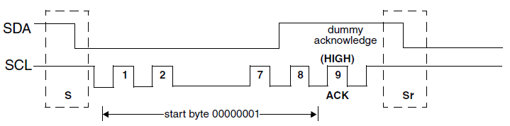
As shown in the figure above, the START BYTE procedure is as follows:
Master generates a START condition.
Master transmits the START byte (0000 0001).
Master transmits the ACK clock pulse. (Present only to conform with the byte handling format used on the bus)
No slave sets the ACK signal to 0.
Master generates a RESTART (Sr) condition.
After the START condition S has been transmitted by a master which requires bus access, the START byte (0000 0001) is transmitted. Another microcontroller can therefore sample the SDA line at a low sampling rate until one of the seven zeros in the START byte is detected. After detection of this LOW level on the SDA line, the microcontroller can switch to a higher sampling rate to find the repeated START condition Sr which is then used for synchronization.
A hardware receiver will reset on receipt of the repeated START condition Sr and will therefore ignore the START byte.
An acknowledge-related clock pulse is generated after the START byte. This is present only to conform with the byte handling format used on the bus. No device is allowed to acknowledge the START byte.
A hardware receiver does not respond to the START BYTE because it is a reserved address and resets after the RESTART condition is generated.
General Call Transfer Protocol
The general call is for addressing every device connected to the I2C bus. However, if a device doesn’t need any of the data supplied within the general call structure, it can ignore this address by not issuing an acknowledgement. If a device does require the data, it will behave as a slave-receiver. The second and following bytes will be acknowledged by every slave-receiver capable of handling this data. The following figure gives the General Call address format. The second byte can be:
‘h06: reset and write programmable part of slave address by hardware.
‘h04: write programmable part of slave address by hardware.
7-bit master address of the hardware master.

When I2C acts as a slave, set IC_ACK_GENERAL_CALL (0x98) bit[0] to 1 to respond with a ACK when it receives a General Call, and a General Call interrupt will be issued. When set this bit to 0, the I2C does not generate General Call interrupts.
NULL DATA Transfer Protocol
NULL DATA transfer is used for some sensors. When IC_DATA_CMD [11] and IC_DATA_CMD [9] is set to 1, I2C would ignore IC_TAR but take the TXFIFO data as slave address. It would only send TXFIFO data in the address phase without any further transmission. The following figure gives the NULL DATA transfer format.

Master Mode
I2C master mode protocols and operation flow are described in this section.
I2C master mode refers to an I2C device acting as the master, which controls the bus and communicates with one or more slaves. In master mode, the I2C is responsible for generating the clock, generating START and STOP conditions, and transferring data according to the protocol.
START and STOP Generation
Refer to register content for IC_DATA_CMD structure.
When operating as an I2C master, putting data into the transmit FIFO causes the I2C to generate a START condition on the I2C bus. Writing a 1 to IC_DATA_CMD [9] causes the hardware to generate a STOP condition on the I2C bus; a STOP condition is not issued if this bit is not set, even if the transmit FIFO is empty. Writing a 1 to IC_DATA_CMD [10] causes the hardware to hold bus after the current data is transmitted and generate a RESTART condition when the next data in FIFO is ready to be transmitted on bus.
When operating as a slave, the I2C does not generate START and STOP conditions, as per the protocol. However, if a read request is made to the I2C, it holds the SCL line low until read data has been supplied to it. This stalls the I2C bus until read data is provided to the slave I2C, or the I2C slave is disabled by writing a 0 to bit0 of the IC_ENABLE.
Speed and Clock Configuration
The bus clock frequency and speed modes of the I2C interfaces are as follows:
I2C interfaces: 2 (I2C0 and I2C1), IC_CLK frequency: 40MHz, support all speed modes.
I2C interfaces: 2 (I2C0 and I2C1), IC_CLK frequency: 100MHz, support all speed modes.
I2C interfaces: 2 (I2C0 and I2C1), IC_CLK frequency: 100MHz, support all speed modes.
I2C interfaces: 2 (I2C0 and I2C1), IC_CLK frequency: 100MHz, support all speed modes.
I2C interfaces: 2 (I2C0 and I2C1), IC_CLK frequency: 100MHz, support all speed modes.
I2C interfaces: 3 (I2C0, I2C1, and I2C2):
I2C0 IC_CLK frequency: 20MHz, support standard mode and fast mode only.
I2C1 and I2C2 IC_CLK frequency: 100MHz, support all speed modes.
I2C interfaces: 2 (I2C0 and I2C1), IC_CLK frequency: 40MHz, support all speed modes.
I2C interfaces: 2 (I2C0 and I2C1), IC_CLK frequency: 100MHz, support all speed modes.
When the I2C is configured as a master, the *CNT registers must be set before any I2C bus transaction can take place in order to ensure proper I/O timing. The *CNT registers are:
IC_SS_SCL_HCNT
IC_SS_SCL_LCNT
IC_FS_SCL_HCNT
IC_FS_SCL_LCNT
IC_HS_SCL_HCNT
IC_HS_SCL_LCNT
SS, FS and HS represent standard mode, fast mode and high speed mode respectively. The *HCNT registers are used to set the number of clock cycles that SCL is held high, and the *LCNT registers are used to set the number of clock cycles that SCL is held low.
Note
It is not necessary to program any of the *CNT registers if the I2C is enabled to operate only as an I2C slave, since these registers are used only to determine the SCL timing requirements for operation as an I2C master.
High and Low Counts Calculation
The calculations below show how to calculate SCL high and low counts for each speed mode in the I2C.
The following conditions should be given:
ic_clk frequency: fic_clk → Tic_clk = 1 / fic_clk
HIGH_TIME: HIGH period of SCL
LOW_TIME: LOW period of SCL
SCL frequency: fSCL → SCLPERIOD = 1 / fSCL
While we want to get HIGH_COUNT & LOW_COUNT, we can derive the equations:
SCL_PERIOD / (HIGH_COUNT + LOW_COUNT) = T_ic_clk
HIGH_COUNT / HIGH_TIME = LOW_COUNT / LOW_TIME
HIGH_TIME + LOW_TIME = SCL_PERIOD
Then, we can get
HIGH_COUNT = HIGH_TIME / T_ic_clk
LOW_COUNT = LOW_TIME / T_ic_clk
Standard Speed Mode and Fast Speed Mode Example
For I2C0/I2C1, fic_clk = 40MHz
ic_clk frequency: fic_clk = 40MHz → Tic_clk = 25ns
According to table 5 of I2C-Bus specification version2.1, FS Mode and SS Mode timing parameters for SCL are specified as:
Standard mode: min. HIGH period of SCL is 4.0us (min. IC_SS_SCL_HCNT = 4.0us/25ns = 160)
Standard mode: min. LOW period of SCL is 4.7us (min. IC_SS_SCL_LCNT = 4.7us/25ns = 188)
Fast mode: min. HIGH period of SCL is 0.6us (min. IC_FS_SCL_HCNT = 0.6us/25ns = 24)
Fast mode: min. LOW period of SCL is 1.3us (min. IC_FS_SCL_LCNT = 1.3us/25ns = 52)
SCL frequency:
100kHz → SCLPERIOD = 10000ns
400kHz → SCLPERIOD = 2500ns
SS Mode (100kHz) :
IC_SS_SCL_HCNT = (10000ns/25ns)*(40/(40+47)) = 183.91 = 184 (round up)
IC_SS_SCL_LCNT = (10000ns/25ns)*(47/(40+47)) = 216.09 = 216 (round down)
FS Mode (400kHz):
IC_FS_SCL_HCNT = (2500ns/25ns)*(6/(6+13)) = 31.58 = 32 (round up)
IC_FS_SCL_LCNT = (2500ns/25ns)*(13/(6+13)) = 68.42 = 68 (round down)
For I2C0/I2C1, fic_clk = 100MHz
ic_clk frequency: fic_clk = 100MHz → Tic_clk = 10ns
According to table 5 of I2C-Bus specification version2.1, FS Mode and SS Mode timing parameters for SCL are specified as:
Standard mode: min. HIGH period of SCL is 4.0us (min. IC_SS_SCL_HCNT = 4.0us/10ns = 400)
Standard mode: min. LOW period of SCL is 4.7us (min. IC_SS_SCL_LCNT = 4.7us/10ns = 470)
Fast mode: min. HIGH period of SCL is 0.6us (min. IC_FS_SCL_HCNT = 0.6us/10ns = 60)
Fast mode: min. LOW period of SCL is 1.3us (min. IC_FS_SCL_LCNT = 1.3us/10ns = 130)
SCL frequency:
100kHz → SCLPERIOD = 10000ns
400kHz → SCLPERIOD = 2500ns
SS Mode (100kHz) :
IC_SS_SCL_HCNT = (10000ns/10ns)*(40/(40+47)) = 459.77 = 460 (round up)
IC_SS_SCL_LCNT = (10000ns/10ns)*(47/(40+47)) = 540.23 = 540 (round down)
FS Mode (400kHz):
IC_FS_SCL_HCNT = (2500ns/10ns)*(6/(6+13)) = 78.95 = 79 (round up)
IC_FS_SCL_LCNT = (2500ns/10ns)*(13/(6+13)) = 171.05 = 171 (round down)
For I2C0/I2C1, fic_clk = 100MHz
ic_clk frequency: fic_clk = 100MHz → Tic_clk = 10ns
According to table 5 of I2C-Bus specification version2.1, FS Mode and SS Mode timing parameters for SCL are specified as:
Standard mode: min. HIGH period of SCL is 4.0us (min. IC_SS_SCL_HCNT = 4.0us/10ns = 400)
Standard mode: min. LOW period of SCL is 4.7us (min. IC_SS_SCL_LCNT = 4.7us/10ns = 470)
Fast mode: min. HIGH period of SCL is 0.6us (min. IC_FS_SCL_HCNT = 0.6us/10ns = 60)
Fast mode: min. LOW period of SCL is 1.3us (min. IC_FS_SCL_LCNT = 1.3us/10ns = 130)
SCL frequency:
100kHz → SCLPERIOD = 10000ns
400kHz → SCLPERIOD = 2500ns
SS Mode (100kHz) :
IC_SS_SCL_HCNT = (10000ns/10ns)*(40/(40+47)) = 459.77 = 460 (round up)
IC_SS_SCL_LCNT = (10000ns/10ns)*(47/(40+47)) = 540.23 = 540 (round down)
FS Mode (400kHz):
IC_FS_SCL_HCNT = (2500ns/10ns)*(6/(6+13)) = 78.95 = 79 (round up)
IC_FS_SCL_LCNT = (2500ns/10ns)*(13/(6+13)) = 171.05 = 171 (round down)
For I2C0/I2C1, fic_clk = 100MHz
ic_clk frequency: fic_clk = 100MHz → Tic_clk = 10ns
According to table 5 of I2C-Bus specification version2.1, FS Mode and SS Mode timing parameters for SCL are specified as:
Standard mode: min. HIGH period of SCL is 4.0us (min. IC_SS_SCL_HCNT = 4.0us/10ns = 400)
Standard mode: min. LOW period of SCL is 4.7us (min. IC_SS_SCL_LCNT = 4.7us/10ns = 470)
Fast mode: min. HIGH period of SCL is 0.6us (min. IC_FS_SCL_HCNT = 0.6us/10ns = 60)
Fast mode: min. LOW period of SCL is 1.3us (min. IC_FS_SCL_LCNT = 1.3us/10ns = 130)
SCL frequency:
100kHz → SCLPERIOD = 10000ns
400kHz → SCLPERIOD = 2500ns
SS Mode (100kHz) :
IC_SS_SCL_HCNT = (10000ns/10ns)*(40/(40+47)) = 459.77 = 460 (round up)
IC_SS_SCL_LCNT = (10000ns/10ns)*(47/(40+47)) = 540.23 = 540 (round down)
FS Mode (400kHz):
IC_FS_SCL_HCNT = (2500ns/10ns)*(6/(6+13)) = 78.95 = 79 (round up)
IC_FS_SCL_LCNT = (2500ns/10ns)*(13/(6+13)) = 171.05 = 171 (round down)
For I2C0/I2C1, fic_clk = 100MHz
ic_clk frequency: fic_clk = 100MHz → Tic_clk = 10ns
According to table 5 of I2C-Bus specification version2.1, FS Mode and SS Mode timing parameters for SCL are specified as:
Standard mode: min. HIGH period of SCL is 4.0us (min. IC_SS_SCL_HCNT = 4.0us/10ns = 400)
Standard mode: min. LOW period of SCL is 4.7us (min. IC_SS_SCL_LCNT = 4.7us/10ns = 470)
Fast mode: min. HIGH period of SCL is 0.6us (min. IC_FS_SCL_HCNT = 0.6us/10ns = 60)
Fast mode: min. LOW period of SCL is 1.3us (min. IC_FS_SCL_LCNT = 1.3us/10ns = 130)
SCL frequency:
100kHz → SCLPERIOD = 10000ns
400kHz → SCLPERIOD = 2500ns
SS Mode (100kHz) :
IC_SS_SCL_HCNT = (10000ns/10ns)*(40/(40+47)) = 459.77 = 460 (round up)
IC_SS_SCL_LCNT = (10000ns/10ns)*(47/(40+47)) = 540.23 = 540 (round down)
FS Mode (400kHz):
IC_FS_SCL_HCNT = (2500ns/10ns)*(6/(6+13)) = 78.95 = 79 (round up)
IC_FS_SCL_LCNT = (2500ns/10ns)*(13/(6+13)) = 171.05 = 171 (round down)
For I2C0, fic_clk = 20MHz; for I2C1/I2C2, fic_clk = 100MHz
ic_clk frequency: fic_clk = 20MHz → Tic_clk = 50ns
According to table 5 of I2C-Bus specification version2.1, FS Mode and SS Mode timing parameters for SCL are specified as:
Standard mode: min. HIGH period of SCL is 4.0us (min. IC_SS_SCL_HCNT = 4.0us/50ns = 80)
Standard mode: min. LOW period of SCL is 4.7us (min. IC_SS_SCL_LCNT = 4.7us/50ns = 94)
Fast mode: min. HIGH period of SCL is 0.6us (min. IC_FS_SCL_HCNT = 0.6us/50ns = 12)
Fast mode: min. LOW period of SCL is 1.3us (min. IC_FS_SCL_LCNT = 1.3us/50ns = 26)
SCL frequency:
100kHz → SCLPERIOD = 10000ns
400kHz → SCLPERIOD = 2500ns
SS Mode (100kHz) :
IC_SS_SCL_HCNT = (10000ns/50ns)*(40/(40+47)) = 91.95 = 92 (round up)
IC_SS_SCL_LCNT = (10000ns/50ns)*(47/(40+47)) = 108.05 = 108 (round down)
FS Mode (400kHz):
IC_FS_SCL_HCNT = (2500ns/50ns)*(6/(6+13)) = 15.79 = 16 (round up)
IC_FS_SCL_LCNT = (2500ns/50ns)*(13/(6+13)) = 34.21 = 34 (round down)
For I2C0/I2C1, fic_clk = 40MHz
ic_clk frequency: fic_clk = 40MHz → Tic_clk = 25ns
According to table 5 of I2C-Bus specification version2.1, FS Mode and SS Mode timing parameters for SCL are specified as:
Standard mode: min. HIGH period of SCL is 4.0us (min. IC_SS_SCL_HCNT = 4.0us/25ns = 160)
Standard mode: min. LOW period of SCL is 4.7us (min. IC_SS_SCL_LCNT = 4.7us/25ns = 188)
Fast mode: min. HIGH period of SCL is 0.6us (min. IC_FS_SCL_HCNT = 0.6us/25ns = 24)
Fast mode: min. LOW period of SCL is 1.3us (min. IC_FS_SCL_LCNT = 1.3us/25ns = 52)
SCL frequency:
100kHz → SCLPERIOD = 10000ns
400kHz → SCLPERIOD = 2500ns
SS Mode (100kHz) :
IC_SS_SCL_HCNT = (10000ns/25ns)*(40/(40+47)) = 183.91 = 184 (round up)
IC_SS_SCL_LCNT = (10000ns/25ns)*(47/(40+47)) = 216.09 = 216 (round down)
FS Mode (400kHz):
IC_FS_SCL_HCNT = (2500ns/25ns)*(6/(6+13)) = 31.58 = 32 (round up)
IC_FS_SCL_LCNT = (2500ns/25ns)*(13/(6+13)) = 68.42 = 68 (round down)
For I2C0/I2C1, fic_clk = 100MHz
ic_clk frequency: fic_clk = 100MHz → Tic_clk = 10ns
According to table 5 of I2C-Bus specification version2.1, FS Mode and SS Mode timing parameters for SCL are specified as:
Standard mode: min. HIGH period of SCL is 4.0us (min. IC_SS_SCL_HCNT = 4.0us/10ns = 400)
Standard mode: min. LOW period of SCL is 4.7us (min. IC_SS_SCL_LCNT = 4.7us/10ns = 470)
Fast mode: min. HIGH period of SCL is 0.6us (min. IC_FS_SCL_HCNT = 0.6us/10ns = 60)
Fast mode: min. LOW period of SCL is 1.3us (min. IC_FS_SCL_LCNT = 1.3us/10ns = 130)
SCL frequency:
100kHz → SCLPERIOD = 10000ns
400kHz → SCLPERIOD = 2500ns
SS Mode (100kHz) :
IC_SS_SCL_HCNT = (10000ns/10ns)*(40/(40+47)) = 459.77 = 460 (round up)
IC_SS_SCL_LCNT = (10000ns/10ns)*(47/(40+47)) = 540.23 = 540 (round down)
FS Mode (400kHz):
IC_FS_SCL_HCNT = (2500ns/10ns)*(6/(6+13)) = 78.95 = 79 (round up)
IC_FS_SCL_LCNT = (2500ns/10ns)*(13/(6+13)) = 171.05 = 171 (round down)
High Speed Mode Example
For I2C0/I2C1, fic_clk = 40MHz, HS mode is supported.
ic_clk frequency: fic_clk = 40MHz → Tic_clk = 25ns
According to table 7 of I2C-Bus specification version2.1, HS mode timing parameters for SCL are specified as:
3.4MHz, bus loading=100pf: min. HIGH period of SCL is 60ns (min. IC_HS_SCL_HCNT = 60ns/25ns = 2.4 → 3)
3.4MHz, bus loading=100pf: min. LOW period of SCL is 120ns (min. IC_HS_SCL_LCNT = 120ns/25ns = 4.8 → 5)
1.7MHz, bus loading=400pf: min. HIGH period of SCL is 160ns (min. IC_HS_SCL_HCNT = 160ns/25ns = 6.4 → 7)
1.7MHz, bus loading=400pf: min. LOW period of SCL is 320ns (min. IC_HS_SCL_LCNT = 320ns/25ns = 12.8 → 13)
SCL frequency:
3.4MHz → SCLPERIOD = 294ns
1.7MHz → SCLPERIOD = 588ns
HS Mode (3.4MHz, bus loading=100pf):
IC_HS_SCL_HCNT = (294ns/25ns)*(6/(6+12)) = 3.9 = 4 (round up)
IC_HS_SCL_LCNT = (294ns/25ns)*(12/(6+12)) = 7.8 = 8 (round up)
HS Mode (1.7MHz, bus loading=400pf):
IC_HS_SCL_HCNT = (588ns/25ns)*(16/(16+32)) = 7.8 = 8 (round up)
IC_HS_SCL_LCNT = (588ns/25ns)*(32/(16+32)) = 15.7 = 16 (round up)
For I2C0/I2C1, fic_clk = 100MHz, HS mode is supported.
ic_clk frequency: fic_clk = 100MHz → Tic_clk = 10ns
According to table 7 of I2C-Bus specification version2.1, HS mode timing parameters for SCL are specified as:
3.4MHz, bus loading=100pf: min. HIGH period of SCL is 60ns (min. IC_HS_SCL_HCNT = 60ns/10ns= 6)
3.4MHz, bus loading=100pf: min. LOW period of SCL is 120ns (min. IC_HS_SCL_LCNT = 120ns/10ns= 12)
1.7MHz, bus loading=400pf: min. HIGH period of SCL is 160ns (min. IC_HS_SCL_HCNT = 160ns/10ns= 16)
1.7MHz, bus loading=400pf: min. LOW period of SCL is 320ns (min. IC_HS_SCL_LCNT = 320ns/10ns= 32)
SCL frequency:
3.4MHz → SCLPERIOD = 294ns
1.7MHz → SCLPERIOD = 588ns
HS Mode (3.4MHz, bus loading=100pf):
IC_HS_SCL_HCNT = (294ns/10ns)*(6/(6+12)) = 9.8 = 10 (round up)
IC_HS_SCL_LCNT = (294ns/10ns)*(12/(6+12)) = 19.6 = 20 (round up)
HS Mode (1.7MHz, bus loading=400pf):
IC_HS_SCL_HCNT = (588ns/10ns)*(16/(16+32)) = 19.6 = 20 (round up)
IC_HS_SCL_LCNT = (588ns/10ns)*(32/(16+32)) = 39.2 = 39 (round down)
For I2C0/I2C1, fic_clk = 100MHz, HS mode is supported.
ic_clk frequency: fic_clk = 100MHz → Tic_clk = 10ns
According to table 7 of I2C-Bus specification version2.1, HS mode timing parameters for SCL are specified as:
3.4MHz, bus loading=100pf: min. HIGH period of SCL is 60ns (min. IC_HS_SCL_HCNT = 60ns/10ns= 6)
3.4MHz, bus loading=100pf: min. LOW period of SCL is 120ns (min. IC_HS_SCL_LCNT = 120ns/10ns= 12)
1.7MHz, bus loading=400pf: min. HIGH period of SCL is 160ns (min. IC_HS_SCL_HCNT = 160ns/10ns= 16)
1.7MHz, bus loading=400pf: min. LOW period of SCL is 320ns (min. IC_HS_SCL_LCNT = 320ns/10ns= 32)
SCL frequency:
3.4MHz → SCLPERIOD = 294ns
1.7MHz → SCLPERIOD = 588ns
HS Mode (3.4MHz, bus loading=100pf):
IC_HS_SCL_HCNT = (294ns/10ns)*(6/(6+12)) = 9.8 = 10 (round up)
IC_HS_SCL_LCNT = (294ns/10ns)*(12/(6+12)) = 19.6 = 20 (round up)
HS Mode (1.7MHz, bus loading=400pf):
IC_HS_SCL_HCNT = (588ns/10ns)*(16/(16+32)) = 19.6 = 20 (round up)
IC_HS_SCL_LCNT = (588ns/10ns)*(32/(16+32)) = 39.2 = 39 (round down)
For I2C0/I2C1, fic_clk = 100MHz, HS mode is supported.
ic_clk frequency: fic_clk = 100MHz → Tic_clk = 10ns
According to table 7 of I2C-Bus specification version2.1, HS mode timing parameters for SCL are specified as:
3.4MHz, bus loading=100pf: min. HIGH period of SCL is 60ns (min. IC_HS_SCL_HCNT = 60ns/10ns= 6)
3.4MHz, bus loading=100pf: min. LOW period of SCL is 120ns (min. IC_HS_SCL_LCNT = 120ns/10ns= 12)
1.7MHz, bus loading=400pf: min. HIGH period of SCL is 160ns (min. IC_HS_SCL_HCNT = 160ns/10ns= 16)
1.7MHz, bus loading=400pf: min. LOW period of SCL is 320ns (min. IC_HS_SCL_LCNT = 320ns/10ns= 32)
SCL frequency:
3.4MHz → SCLPERIOD = 294ns
1.7MHz → SCLPERIOD = 588ns
HS Mode (3.4MHz, bus loading=100pf):
IC_HS_SCL_HCNT = (294ns/10ns)*(6/(6+12)) = 9.8 = 10 (round up)
IC_HS_SCL_LCNT = (294ns/10ns)*(12/(6+12)) = 19.6 = 20 (round up)
HS Mode (1.7MHz, bus loading=400pf):
IC_HS_SCL_HCNT = (588ns/10ns)*(16/(16+32)) = 19.6 = 20 (round up)
IC_HS_SCL_LCNT = (588ns/10ns)*(32/(16+32)) = 39.2 = 39 (round down)
For I2C0/I2C1, fic_clk = 100MHz, HS mode is supported.
ic_clk frequency: fic_clk = 100MHz → Tic_clk = 10ns
According to table 7 of I2C-Bus specification version2.1, HS mode timing parameters for SCL are specified as:
3.4MHz, bus loading=100pf: min. HIGH period of SCL is 60ns (min. IC_HS_SCL_HCNT = 60ns/10ns= 6)
3.4MHz, bus loading=100pf: min. LOW period of SCL is 120ns (min. IC_HS_SCL_LCNT = 120ns/10ns= 12)
1.7MHz, bus loading=400pf: min. HIGH period of SCL is 160ns (min. IC_HS_SCL_HCNT = 160ns/10ns= 16)
1.7MHz, bus loading=400pf: min. LOW period of SCL is 320ns (min. IC_HS_SCL_LCNT = 320ns/10ns= 32)
SCL frequency:
3.4MHz → SCLPERIOD = 294ns
1.7MHz → SCLPERIOD = 588ns
HS Mode (3.4MHz, bus loading=100pf):
IC_HS_SCL_HCNT = (294ns/10ns)*(6/(6+12)) = 9.8 = 10 (round up)
IC_HS_SCL_LCNT = (294ns/10ns)*(12/(6+12)) = 19.6 = 20 (round up)
HS Mode (1.7MHz, bus loading=400pf):
IC_HS_SCL_HCNT = (588ns/10ns)*(16/(16+32)) = 19.6 = 20 (round up)
IC_HS_SCL_LCNT = (588ns/10ns)*(32/(16+32)) = 39.2 = 39 (round down)
I2C0 does not support HS mode; for I2C1/2, fic_clk = 100MHz, HS mode is supported.
ic_clk frequency: fic_clk = 100MHz → Tic_clk = 10ns
According to table 7 of I2C-Bus specification version2.1, HS mode timing parameters for SCL are specified as:
3.4MHz, bus loading=100pf: min. HIGH period of SCL is 60ns (min. IC_HS_SCL_HCNT = 60ns/10ns= 6)
3.4MHz, bus loading=100pf: min. LOW period of SCL is 120ns (min. IC_HS_SCL_LCNT = 120ns/10ns= 12)
1.7MHz, bus loading=400pf: min. HIGH period of SCL is 160ns (min. IC_HS_SCL_HCNT = 160ns/10ns= 16)
1.7MHz, bus loading=400pf: min. LOW period of SCL is 320ns (min. IC_HS_SCL_LCNT = 320ns/10ns= 32)
SCL frequency:
3.4MHz → SCLPERIOD = 294ns
1.7MHz → SCLPERIOD = 588ns
HS Mode (3.4MHz, bus loading=100pf):
IC_HS_SCL_HCNT = (294ns/10ns)*(6/(6+12)) = 9.8 = 10 (round up)
IC_HS_SCL_LCNT = (294ns/10ns)*(12/(6+12)) = 19.6 = 20 (round up)
HS Mode (1.7MHz, bus loading=400pf):
IC_HS_SCL_HCNT = (588ns/10ns)*(16/(16+32)) = 19.6 = 20 (round up)
IC_HS_SCL_LCNT = (588ns/10ns)*(32/(16+32)) = 39.2 = 39 (round down)
For I2C0/I2C1, fic_clk = 40MHz, HS mode is supported.
ic_clk frequency: fic_clk = 40MHz → Tic_clk = 25ns
According to table 7 of I2C-Bus specification version2.1, HS mode timing parameters for SCL are specified as:
3.4MHz, bus loading=100pf: min. HIGH period of SCL is 60ns (min. IC_HS_SCL_HCNT = 60ns/25ns = 2.4 → 3)
3.4MHz, bus loading=100pf: min. LOW period of SCL is 120ns (min. IC_HS_SCL_LCNT = 120ns/25ns = 4.8 → 5)
1.7MHz, bus loading=400pf: min. HIGH period of SCL is 160ns (min. IC_HS_SCL_HCNT = 160ns/25ns = 6.4 → 7)
1.7MHz, bus loading=400pf: min. LOW period of SCL is 320ns (min. IC_HS_SCL_LCNT = 320ns/25ns = 12.8 → 13)
SCL frequency:
3.4MHz → SCLPERIOD = 294ns
1.7MHz → SCLPERIOD = 588ns
HS Mode (3.4MHz, bus loading=100pf):
IC_HS_SCL_HCNT = (294ns/25ns)*(6/(6+12)) = 3.9 = 4 (round up)
IC_HS_SCL_LCNT = (294ns/25ns)*(12/(6+12)) = 7.8 = 8 (round up)
HS Mode (1.7MHz, bus loading=400pf):
IC_HS_SCL_HCNT = (588ns/25ns)*(16/(16+32)) = 7.8 = 8 (round up)
IC_HS_SCL_LCNT = (588ns/25ns)*(32/(16+32)) = 15.7 = 16 (round up)
For I2C0/I2C1, fic_clk = 100MHz, HS mode is supported.
ic_clk frequency: fic_clk = 100MHz → Tic_clk = 10ns
According to table 7 of I2C-Bus specification version2.1, HS mode timing parameters for SCL are specified as:
3.4MHz, bus loading=100pf: min. HIGH period of SCL is 60ns (min. IC_HS_SCL_HCNT = 60ns/10ns= 6)
3.4MHz, bus loading=100pf: min. LOW period of SCL is 120ns (min. IC_HS_SCL_LCNT = 120ns/10ns= 12)
1.7MHz, bus loading=400pf: min. HIGH period of SCL is 160ns (min. IC_HS_SCL_HCNT = 160ns/10ns= 16)
1.7MHz, bus loading=400pf: min. LOW period of SCL is 320ns (min. IC_HS_SCL_LCNT = 320ns/10ns= 32)
SCL frequency:
3.4MHz → SCLPERIOD = 294ns
1.7MHz → SCLPERIOD = 588ns
HS Mode (3.4MHz, bus loading=100pf):
IC_HS_SCL_HCNT = (294ns/10ns)*(6/(6+12)) = 9.8 = 10 (round up)
IC_HS_SCL_LCNT = (294ns/10ns)*(12/(6+12)) = 19.6 = 20 (round up)
HS Mode (1.7MHz, bus loading=400pf):
IC_HS_SCL_HCNT = (588ns/10ns)*(16/(16+32)) = 19.6 = 20 (round up)
IC_HS_SCL_LCNT = (588ns/10ns)*(32/(16+32)) = 39.2 = 39 (round down)
Note
Since the slave may stretch the SCL line, the actual speed is a little bit lower than 100kbps/400kbps/3.4Mbps if we set the above calculated values. In order to reach the accurate speed, calculated values should be reduced a little according to test results.
Master-Transmitter and Slave-Receiver
All data is transmitted in byte format, with no limit on the number of bytes transferred per data transfer. After the master sends the address and R/W bit or the master transmits a byte of data to the slave, the slave-receiver must respond with the acknowledge signal (ACK). When a slave-receiver does not respond with an ACK pulse, the master aborts the transfer by issuing a STOP condition. The slave must leave the SDA line high so that the master can abort the transfer.
If the master-transmitter is transmitting data as shown below, then the slave-receiver responds to the master-transmitter with an acknowledge pulse after every byte of data is received.

Master-Receiver and Slave-Transmitter
If the master is receiving data as shown below, then the master responds to the slave-transmitter with an acknowledge pulse after a byte of data has been received, except for the last byte. This is the way the master-receiver notifies the slave-transmitter that this is the last byte. The slave-transmitter relinquishes the SDA line after detecting the No Acknowledge (NACK) so that the master can issue a STOP condition.

For 10-bit address, the transfer process is also shown below.
Address phase 1: master sends {5’b11110, slave address [9:8], 1’b0}; R/W=1’b0 means master will send data in data phase.
Data phase 1: master sends slave address [7:0];
A restart is set to indicate the direction toggle of data transfer.
Address phase 2: master sends {5’b11110, slave address [9:8], 1’b1}; R/W=1’b1 means master will receive data in data phase.
Data phase 2: master receives data from slave.
When a master does not want to relinquish the bus with a STOP condition, the master can issue a RESTART condition. This is identical to a START condition except it occurs after the ACK pulse. Operating in master mode, the I2C can then communicate with the same slave using a transfer of a different direction.
Combined Formats
Combined format transactions means that the data send direction may change during a transfer. For example, a master may send data and then receive data or vice versa without releasing the I2C bus. The combined format is illustrated below.

The I2C supports combined format transactions for both 7-bit or 10-bit addressing modes. The I2C does not support mixed address—that is, a 7-bit address transaction followed by a 10-bit address transaction or vice versa—in combined format transaction.
To initiate combined format transfers, IC_CON.IC_RESTART_EN should be set to 1. With this value set and operating as a master, when the I2C completes an I2C transfer, it checks the transmit FIFO and executes the next transfer. If the direction of this transfer differs from the previous transfer, the combined format is used to issue the transfer. If the transmit FIFO is empty when the current I2C transfer completes, IC_DATA_CMD [9] is checked.
If set to 1, a STOP bit is issued.
If set to 0, the SCL is held low until the next command is written to the transmit FIFO.
Multi-Master
I2C supports multi-master functionality, which allows multiple masters to reside on the bus without conflict or data loss.
SCL Clock Synchronization
When two or more masters try to transfer information on the bus at the same time, they must arbitrate and synchronize the SCL clock.
All masters generate their own clock to transfer messages. Data is valid only during the high period of SCL clock. Clock synchronization is performed using the wired-AND connection to the SCL signal.
When a master pulls the SCL line LOW, it starts counting its LOW period. It attempts to transition the SCL line to HIGH at the end of this period. However, if another master is still holding the SCL line LOW, the wired-AND connection prevents the line from going HIGH. The first master then enters a HIGH wait state, stopping its clock generator until the SCL line actually transitions to HIGH.
All masters then count off their high time and the master with the shortest high time transitions the SCL line to 0. The masters then count out their low time and the one with the longest low time forces other masters into a HIGH wait state. Therefore, a synchronized SCL clock is generated, which is illustrated below.
CLKA is I2C bus clock generated by master A, and CLKB is I2C bus clock generated by master B. SCL in the illustration above and the one below is wire-AND between CLKA and CLKB.

SDA Arbitration
The I2C bus protocol allows multiple masters to reside on the same bus. An I2C master may start a transfer only if the bus is free. Two or more I2C masters may start a transfer in a very short time interval by generating a START condition.
If two masters send a START on the bus within the minimum hold time (tHD, STA), arbitration takes place on the SDA line, while the SCL line is HIGH. The master that transmits a HIGH (1) level while the other master transmits a LOW (0) level loses arbitration, and turns off its data and clock output stage.
The SCL signal is the wired-AND result of the SCL signals from all masters.
The following figure illustrates the timing of when two masters are arbitrating on the bus.
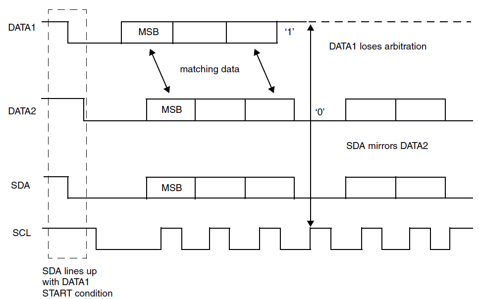
For SS-mode or FS-mode masters, arbitration may continue through address, address ACK, data, and data ACK bits. Special attention must be paid, during a serial transfer, if the arbitration procedure is still in progress at the moment when a repeated START condition or a STOP condition is transmitted to the I2C bus. If it's possible for such a situation to occur, the masters involved must send this repeated START condition or STOP condition at the same position in the format frame. In other words, arbitration isn't allowed between:
A repeated START condition and a data bit
A STOP condition and a data bit
A repeated START condition and a STOP condition.
As an HS-mode master has a unique 8-bit master code, it will always finish the arbitration during the first byte (sending of HS master code). This 8-bit code is defined by the system designer and is set by writing to the IC_HS_MAR (High Speed Master Mode Code Address) register. Because the codes are unique, only one master can win arbitration, which occurs by the end of the transmission of the high-speed master code. Control of the bus is determined by address or master code and data sent by competing masters, so there is no central master nor any order of priority on the bus.
If a master also incorporates a slave function and it loses arbitration during the addressing stage, the winning master may be trying to address it. The losing master must therefore switch over immediately to its slave mode.
Slaves are not involved in the arbitration process.
Operation Flow
This section discusses master mode procedures.
Initial Configuration
The configuration procedure for master mode is as follows:
Disable the I2C by writing 0 to the IC_ENABLE register.
Write to the IC_CON register to set the desired speed mode (bit[2:1]) of the transfer. Writing 1 to bit[0] and 1 to bit[6] and bit[7] to enable the Master Module and disable the Slave Module.
Write to the IC_TAR register the address of the I2C device to be addressed. It also indicates whether a General Call or a START BYTE command is going to be performed by I2C. The addressing mode of the I2C master-initiated transfers, either 7-bit or 10-bit addressing, is controlled by the IC_10BITADDR_MASTER bit (bit[12]).
Enable the I2C by writing 1 to the IC_ENABLE register.
Write transfer direction and data to be sent to the IC_DATA_CMD register. If the IC_DATA_CMD register is written before the I2C is enabled, the data and commands are lost as the buffers are kept cleared when I2C is disabled.
The I2C initialization configuration in master mode is illustrated below.

Dynamic IC_TAR Update
For the master I2C, the target address (IC_TAR bit[9:0]) and address format (IC_TAR.IC_10BITADDR_MASTER) can be changed dynamically without having to disable I2C. However, when I2C is acting as a slave, the component must be disabled before any changes can be made to the address.
You can dynamically write to the IC_TAR register provided the following conditions are met:
I2C is not enabled (IC_ENABLE =0); OR
I2C is enabled (IC_ENABLE =1); AND
I2C is enabled to operate in Master mode (IC_CON [0]=1); AND
I2C is NOT engaged in any Master (Tx, Rx) operation (IC_STATUS [5]=0); AND
There are NO entries in the Tx FIFO (IC_STATUS [2]=1)
Master Transmit and Master Receive
To transmit data, write the data to be written to the lower byte (bit[7:0]) of the I2C Rx/Tx Data Buffer and Command Register IC_DATA_CMD. The bit[8] (R/W) should be written to 0 for I2C write operations.
Subsequently, a read command may be issued by writing “don’t cares” to the bit[7:0] of the IC_DATA_CMD register, and a 1 should be written to the R/W bit.
The I2C master continues to initiate transfers as long as there are commands present in the transmit FIFO.
If the STOP bit (bit[9]) is set to 1, the I2C inserts a STOP condition after completing the current transfer.
The I2C supports switching back and forth between reading and writing dynamically. For the combined transfer, a 1 should be written to the RESTART bit (bit[10]) of the last command before the transfer direction reverses.
Slave Mode
This section describes the I2C slave mode functionality, including slave addresses and software operation flow.
Slave Mode Dual Own Address
The I2C has dual own address:
Slave 1 supports 7-bit or 10-bit address modes.
Slave 2 only supports 7-bit address mode.
Set IC_CON [7:6] (
0x10) to enable slave 1 or slave 2.Slave 1 address is set in IC_SAR (
0x08), which supports 7 bits or 10 bits.Slave 2 address is set in IC_SAR2 (
0xF4), which only supports 7 bits.IC_CON [3] (
0x10) IC_10BITADDR_SLAVE controls whether the I2C responds to 7-bit or 10-bit address.If slave 1 and slave 2 are both enabled, the one who matches address would response ACK.
Operation Flow
This section discusses slave mode procedures.
Initial Configuration
To use the I2C as a slave, perform the following steps:
Disable the I2C by writing a 0 to bit[0] of the IC_ENABLE register.
Write the IC_SAR register (bit[9:0]) to set the slave address. This is the address to which the I2C responds.
Write the IC_CON register to specify which type of addressing is supported (7-bit or 10-bit by setting bit[3]). Enable the I2C in slave-only mode by writing a 0 into bit[6] and bit[7] (IC_SLAVE_DISABLE) and a 0 to bit[0] (MASTER_MODE).
Enable the I2C by writing a 1 to bit[0] of the IC_ENABLE register.
Note
The slaves and masters do not have to be programmed with the same address type (either 7-bit or 10-bit). For instance, a slave can be programmed with 7-bit addressing and a master with 10-bit addressing, and vice versa.
The I2C initialization configuration in slave mode is illustrated below.

Slave-Transmitter Operation for a Single Byte
When another I2C master device on the bus addresses the I2C and requests data, the I2C acts as a slave-transmitter and the following steps occur:
The other I2C master device initiates an I2C transfer with an address that matches the slave address in the IC_SAR register of the I2C.
The I2C acknowledges the sent address and recognizes the direction of the transfer to indicate that it is acting as a slave-transmitter.
The I2C asserts the RD_REQ interrupt (bit[5] of the IC_RAW_INTR_STAT register) and holds the SCL line low. It is in a wait state until software responds.
Reads that indicate IC_RAW_INTR_STAT [5] (RD_REQ bit) being set to 1 must be treated as the equivalent of the RD_REQ interrupt being asserted.
Software must then act to satisfy the I2C transfer.
If there is any data remaining in the Tx FIFO before receiving the read request, then the I2C asserts a TX_ABRT interrupt (bit[6] of the IC_RAW_INTR_STAT register) to flush the old data from the Tx FIFO.
Note
Because the Tx FIFO is forced into a flushed/reset state whenever a TX_ABRT Interrupt event occurs, it is necessary for software to release the I2C from this state by reading the IC_CLR_TX_ABRT register before attempting to write into the Tx FIFO. See register IC_RAW_INTR_STAT for more details.
Reads that indicate bit[6] (TX_ABRT) being set to 1 must be treated as the equivalent of the TX_ABRT interrupt being asserted.
There is no further action required from software.
Software writes to the IC_DATA_CMD register with the data to be written (by writing a 0 to bit[8]).
Software must clear the RD_REQ and TX_ABRT interrupts (bit[5] and bit[6] respectively) of the IC_RAW_INTR_STAT register before proceeding.
The I2C releases the SCL and transmits the byte.
The master may hold the I2C bus by issuing a RESTART condition or release the bus by issuing a STOP condition.
The I2C data transmission in slave mode is illustrated below.

Slave-Receiver Operation for a Single Byte
When another I2C master device on the bus addresses the I2C and is sending data, the I2C acts as a slave-receiver and the following steps occur:
The other I2C master device initiates an I2C transfer with an address that matches the I2C slave address in the IC_SAR register.
The I2C acknowledges the sent address and recognizes the direction of the transfer to indicate that the I2C is acting as a slave-receiver.
I2C receives the transmitted byte and places it in the receive buffer.
Note
If the Rx FIFO is completely filled with data when a byte is pushed, then an overflow occurs and the I2C continues with subsequent I2C transfers. Because a NACK is not generated, software must recognize the overflow when indicated by the I2C (by the RX_OVER bit in the IC_INTR_STAT register) and take appropriate actions to recover from lost data.
I2C asserts the RX_FULL interrupt (IC_RAW_INTR_STAT [2] register).
If the RX_FULL interrupt has been masked, due to setting IC_INTR_MASK [2] register to 0 or setting IC_TX_TL to a value larger than 0, then it is recommended that a timing routine be implemented for periodic reads of the IC_STATUS register. Reads of the IC_STATUS register, with bit[3] (RFNE) set at 1, must then be treated by software as the equivalent of the RX_FULL interrupt being asserted.
Software may read the byte from the IC_DATA_CMD register (bit[7:0]).
The other master device may hold the I2C bus by issuing a RESTART condition or release the bus by issuing a STOP condition.
The I2C data reception in slave mode is illustrated below.

Slave-Transfer Operation for Bulk Transfers
The I2C slave supports bulk transfers by utilizing the hardware Tx FIFO. Compared to the traditional single-byte transaction that raises an interrupt for each byte, bulk transfers allow the Tx FIFO to continuously supply data, which significantly reduces bus latency. This feature is only valid when the I2C acts as a slave-transmitter.
The core mechanism of bulk transfers is as follows:
Read Request: When a remote master initiates a read request and the slave’s Tx FIFO is empty, the hardware holds the SCL line low (clock stretching) and asserts the read request interrupt (RD_REQ), waiting for software to write data.
Bulk Filling the FIFO: While servicing the RD_REQ interrupt, software should clear the interrupt and can write a packet of multiple bytes into the Tx FIFO at once.
Hardware Continuous Transmission: As long as there is data available in the Tx FIFO and the remote master continues to ACK the received data, the I2C hardware will continuously transmit data in the background without holding the SCL line low or asserting additional RD_REQ interrupts.
Transfer Boundary Handling:
Data Underflow: If the Tx FIFO runs empty during transmission but the master ACKs the last byte to request more data, the slave will again hold the SCL line low and assert a new RD_REQ interrupt.
Data Overflow: If the software writes more bytes into the Tx FIFO than the master actually requests, when the master terminates the transfer early (issues NACK and STOP), the I2C hardware automatically clears the Tx FIFO and discards the excess bytes.
Note
If the RD_REQ interrupt is masked (bit[5] of the IC_INTR_STAT register is set to 0), it is recommended to implement a timing routine to periodically poll the IC_RAW_INTR_STAT register. A read operation returning bit[5] set to 1 should be treated as the equivalent of the RD_REQ interrupt assertion.
FIFO Management
FIFO Status and Bus Behavior
The I2C does not generate a STOP if the Tx FIFO becomes empty; in this situation, the component holds the SCL line low, stalling the bus until a new entry is available in the Tx FIFO. A STOP condition is generated only when the user specifically requests it by setting bit[9] (STOP bit) of the command written to IC_DATA_CMD register. The following figure shows the fields in IC_DATA_CMD. Refer to the register description for more detailed information.

The following figures illustrate the behavior of the I2C when the Tx FIFO becomes empty while operating as a master transmitter and a master receiver respectively, as well as showing the generation of a STOP condition.

Master transmitter — Tx FIFO empties/STOP generation

Master receiver — Tx FIFO empties/STOP generation
The following figures illustrate configurations where the user can control the generation of RESTART conditions on the I2C bus. If bit[10] (RESTART) of the IC_DATA_CMD register is set and the restart capability is enabled (IC_RESTART_EN =1), a RESTART is generated before the data byte is written to or read from the slave. If the restart capability is not enabled a STOP followed by a START is generated in place of the RESTART. The first figure illustrates the situation during operation as a master transmitter, while the second shows the same scenario during operation as a master receiver.

Master transmitter — RESTART bit of IC_DATA_CMD set

Master receiver — RESTART bit of IC_DATA_CMD set
The following figures illustrate operation as a master transmitter and a master receiver respectively where the STOP bit of the IC_DATA_CMD register is set and the Tx FIFO is not empty.

Master transmitter — STOP bit of IC_DATA_CMD set/Tx FIFO not empty

Master receiver — STOP bit of IC_DATA_CMD set/Tx FIFO not empty
SDA/SCL Digital Filter
The I2C provides filtering on the SDA and SCL inputs, suppressing noise and signal spikes, improving communication stability.
Set the IC_DIG_FLTR_SEL bit in the IC_FILTER register to 1 to enable the filter.
Adjust the width of noise or glitches that can be suppressed by configuring the IC_DIG_FLTR_DEG field in the IC_FILTER register. The larger the value, the longer the duration of glitches that can be suppressed, but the longer the signal delay after filtering.
Noise or signal spikes with duration less than
(IC_DIG_FLTR_DEG >> 1) + 1ic_clk cycles could be suppressed.The total delay introduced by the filter is
(IC_DIG_FLTR_DEG >> 1) + 3ic_clk cycles (including 2 cycles of hardware fixed overhead).
Note
The threshold condition for determining valid signals in the underlying circuit of the I2C filter is “whether the level duration is greater than half of the configured width”. The hardware logic obtains this threshold by dividing the register value by 2, and the “divide by 2” operation in digital circuits is equivalent to directly right-shifting the data by one bit. Therefore, the least significant bit (bit[0]) of the register will be directly discarded, and its value will not affect the filtering behavior at all.
Programmable SDA Hold Time
In I2C communication, to ensure the receiver can correctly read the data, the transmitter must hold the level on the SDA line for a period of time after the SCL falling edge (i.e., SDA hold time).
When configuring the SDA hold time of the I2C, the actual effective number of clock cycles depends on the current role of the I2C and the transmission phase. It mainly depends on the configuration value of the IC_SDA_HOLD register and the delay of the digital filter.
Role |
Phase |
Clock Source |
Actual SDA Hold Time (ic_clk cycles) |
|---|---|---|---|
Master |
ADDRESS/MSCODE |
External bus SCL (requires digital filtering to handle arbitration) |
MAX ( IC_DIG_FLTR_DEG >> 1 + 5, IC_SDA_HOLD ) |
Master |
WDATA |
Internally generated SCL (drives the bus directly, no filter delay) |
IC_SDA_HOLD |
Slave |
WDATA |
External bus SCL (requires digital filtering, passively follows) |
MAX ( IC_DIG_FLTR_DEG >> 1 + 5, IC_SDA_HOLD ) |
Note
The 8th bit of data is not under control of IC_SDA_HOLD, because after the 8th SCL clock negative edge, receiver controls the SDA line to respond ACK or NACK.
The IC_SDA_HOLD register can be programmed only when I2C is disabled (IC_ENABLE =0).
According to table 5 in I2C-Bus specification version2.1, the maximum hold time in SS mode is 3.45us, in FS mode is 0.9us. According to table 7, in HS mode, the maximum hold time is 70ns with a bus load of 100pf, and 150ns with a bus load of 400pf.
DMA Controller Interface
The I2C has an optional built-in DMA capability; it has a handshaking interface to a DMA Controller to request and control transfers.
Data transfers between memory and the IC_DATA_CMD register through the DMA interface allow the I2C to efficiently handle data transfers without consuming CPU resources.
Enabling the DMA Controller Interface
To enable the DMA Controller interface on the I2C, you must configure the DMA Control Register (IC_DMA_CR):
Write 1 to the TDMAE bit field of the IC_DMA_CR register to enable the I2C Tx DMA handshaking interface.
Write 1 to the RDMAE bit field of the IC_DMA_CR register to enable the I2C Rx DMA handshaking interface.
Tx FIFO Watermark Level
During I2C serial transfers, Tx FIFO requests are made to the DMA Controller whenever the number of entries in the Tx FIFO is less than or equal to the value of the DMA Transmit Data Level Register (IC_DMA_TDLR). The DMA Controller responds by writing a burst of data to the Tx FIFO buffer.
Note
Underflow Prevention Mechanism: The DMA must fetch data frequently enough to prevent the Tx FIFO from running empty. If a FIFO underflow occurs, the hardware will erroneously insert a STOP signal on the I2C bus, causing communication interruption. Therefore, the user must set a reasonable transmit watermark level for the application.
To minimize the number of transactions per block while avoiding underflow for optimal operation, the DMA destination burst size (DMA.CTLx.DEST_MSIZE) must be set to the available space in the Tx FIFO when the request is triggered; the calculation formula is:
DMA.CTLx.DEST_MSIZE = I2C.FIFO_DEPTH - I2C.IC_DMA_TDLR
Rx FIFO Watermark Level
During I2C serial reception, Rx FIFO requests are made to the DMA Controller whenever the number of entries in the Rx FIFO is equal to or greater than the receive watermark (i.e., IC_DMA_RDLR + 1). The DMA responds by fetching a burst of data of length CTLx.SRC_MSIZE from the Rx FIFO.
Note
Overflow Prevention Mechanism: The DMA must promptly fetch data from the Rx FIFO to prevent it from being filled by incoming data, causing data overflow and loss.
Similar to the transmit watermark strategy, to minimize the probability of overflow and achieve optimal performance, the DMA source burst fetch size (DMA.CTLx.SRC_MSIZE) should accurately equal the receive watermark trigger level; the calculation formula is:
DMA.CTLx.SRC_MSIZE = I2C.IC_DMA_RDLR + 1
DMA Transfer Control Registers
The I2C module provides registers to control the DMA transfer process: the IC_DMA_CMD and IC_DMA_DATA_LEN registers. The IC_DMA_DATA_LEN is used to configure the transfer data length. The IC_DMA_CMD register contains several fields:
ENABLE: Enables the I2C DMA mode.CMD: Controls the transfer direction of the master.RESTART: Indicates whether to drive a RESTART signal after the last data byte is transferred.STOP: Indicates whether to drive a STOP signal after the last data byte is transferred.
The usage in Master and Slave modes is introduced below.
Master Mode
The I2C DMA Tx configuration steps are as follows:
Initialize the GDMA Tx channel: Configure the source address (memory), destination address (I2C Tx FIFO), and transfer completion interrupt ISR.
Configure the I2C DMA control registers: Write the total number of bytes to be transmitted into the IC_DMA_DATA_LEN register; set the DMODE_ENABLE and DMODE_STOP bits of the IC_DMA_CMD register to 1, causing the I2C to automatically generate a STOP condition after the last byte is transferred.
Enable Tx DMA (TDMAE bit in the IC_DMA_CR register) to start transmitting. The DMA Tx will be triggered when the FIFO data level falls below IC_DMA_TDLR.
In the GDMA Tx interrupt ISR, the following operations should be executed:
Poll IC_STATUS.TFE to wait for the Tx FIFO to empty, ensuring all data has been completely transmitted to the bus.
If there is remaining data to be transmitted, restart the DMA transfer.
Upon total completion, release the GDMA channel and end the transmission.
The I2C DMA Rx configuration steps are similar to Tx:
Initialize the GDMA Rx channel: Configure the source address (I2C Rx FIFO), destination address (memory), and transfer completion interrupt ISR.
Configure the I2C DMA control registers: Write the number of bytes to be received into the IC_DMA_DATA_LEN register; set the DMODE_ENABLE, DMODE_STOP, and DMODE_CMD bits of the IC_DMA_CMD register to 1, enabling the I2C to automatically and cyclically issue read commands to the bus.
Enable Rx DMA (RDMAE bit in the IC_DMA_CR register) to start receiving. The DMA Rx will be triggered when the FIFO data level exceeds IC_DMA_RDLR.
In the GDMA Rx interrupt ISR:
If there is remaining data, update the GDMA destination address and block size, then restart the transfer.
Upon total completion, release the GDMA channel and end the transmission.
Slave Mode
The steps are similar to Master mode, with the following differences:
Before enabling Rx DMA, poll IC_RAW_INTR_STAT.RX_FULL to wait until the Rx FIFO is full before starting reception.
Before enabling Tx DMA, poll IC_RAW_INTR_STAT.RD_REQ to wait for the master to issue a read request before starting transmission.
There is no need to configure the DMODE_STOP and DMODE_CMD bits.
Not supported.
Not supported.
Not supported.
Not supported.
Not supported.
The I2C has an optional built-in DMA capability; it has a handshaking interface to a DMA Controller to request and control transfers.
Data transfers between memory and the IC_DATA_CMD register through the DMA interface allow the I2C to efficiently handle data transfers without consuming CPU resources.
Enabling the DMA Controller Interface
To enable the DMA Controller interface on the I2C, you must configure the DMA Control Register (IC_DMA_CR):
Write 1 to the TDMAE bit field of the IC_DMA_CR register to enable the I2C Tx DMA handshaking interface.
Write 1 to the RDMAE bit field of the IC_DMA_CR register to enable the I2C Rx DMA handshaking interface.
Tx FIFO Watermark Level
During I2C serial transfers, Tx FIFO requests are made to the DMA Controller whenever the number of entries in the Tx FIFO is less than or equal to the value of the DMA Transmit Data Level Register (IC_DMA_TDLR). The DMA Controller responds by writing a burst of data to the Tx FIFO buffer.
Note
Underflow Prevention Mechanism: The DMA must fetch data frequently enough to prevent the Tx FIFO from running empty. If a FIFO underflow occurs, the hardware will erroneously insert a STOP signal on the I2C bus, causing communication interruption. Therefore, the user must set a reasonable transmit watermark level for the application.
To minimize the number of transactions per block while avoiding underflow for optimal operation, the DMA destination burst size (DMA.CTLx.DEST_MSIZE) must be set to the available space in the Tx FIFO when the request is triggered; the calculation formula is:
DMA.CTLx.DEST_MSIZE = I2C.FIFO_DEPTH - I2C.IC_DMA_TDLR
Rx FIFO Watermark Level
During I2C serial reception, Rx FIFO requests are made to the DMA Controller whenever the number of entries in the Rx FIFO is equal to or greater than the receive watermark (i.e., IC_DMA_RDLR + 1). The DMA responds by fetching a burst of data of length CTLx.SRC_MSIZE from the Rx FIFO.
Note
Overflow Prevention Mechanism: The DMA must promptly fetch data from the Rx FIFO to prevent it from being filled by incoming data, causing data overflow and loss.
Similar to the transmit watermark strategy, to minimize the probability of overflow and achieve optimal performance, the DMA source burst fetch size (DMA.CTLx.SRC_MSIZE) should accurately equal the receive watermark trigger level; the calculation formula is:
DMA.CTLx.SRC_MSIZE = I2C.IC_DMA_RDLR + 1
DMA Transfer Control Registers
The I2C module provides registers to control the DMA transfer process: the IC_DMA_CMD and IC_DMA_DATA_LEN registers. The IC_DMA_DATA_LEN is used to configure the transfer data length. The IC_DMA_CMD register contains several fields:
ENABLE: Enables the I2C DMA mode.CMD: Controls the transfer direction of the master.RESTART: Indicates whether to drive a RESTART signal after the last data byte is transferred.STOP: Indicates whether to drive a STOP signal after the last data byte is transferred.
The usage in Master and Slave modes is introduced below.
Master Mode
The I2C DMA Tx configuration steps are as follows:
Initialize the GDMA Tx channel: Configure the source address (memory), destination address (I2C Tx FIFO), and transfer completion interrupt ISR.
Configure the I2C DMA control registers: Write the total number of bytes to be transmitted into the IC_DMA_DATA_LEN register; set the DMODE_ENABLE and DMODE_STOP bits of the IC_DMA_CMD register to 1, causing the I2C to automatically generate a STOP condition after the last byte is transferred.
Enable Tx DMA (TDMAE bit in the IC_DMA_CR register) to start transmitting. The DMA Tx will be triggered when the FIFO data level falls below IC_DMA_TDLR.
In the GDMA Tx interrupt ISR, the following operations should be executed:
Poll IC_STATUS.TFE to wait for the Tx FIFO to empty, ensuring all data has been completely transmitted to the bus.
If there is remaining data to be transmitted, restart the DMA transfer.
Upon total completion, release the GDMA channel and end the transmission.
The I2C DMA Rx configuration steps are similar to Tx:
Initialize the GDMA Rx channel: Configure the source address (I2C Rx FIFO), destination address (memory), and transfer completion interrupt ISR.
Configure the I2C DMA control registers: Write the number of bytes to be received into the IC_DMA_DATA_LEN register; set the DMODE_ENABLE, DMODE_STOP, and DMODE_CMD bits of the IC_DMA_CMD register to 1, enabling the I2C to automatically and cyclically issue read commands to the bus.
Enable Rx DMA (RDMAE bit in the IC_DMA_CR register) to start receiving. The DMA Rx will be triggered when the FIFO data level exceeds IC_DMA_RDLR.
In the GDMA Rx interrupt ISR:
If there is remaining data, update the GDMA destination address and block size, then restart the transfer.
Upon total completion, release the GDMA channel and end the transmission.
Slave Mode
The steps are similar to Master mode, with the following differences:
Before enabling Rx DMA, poll IC_RAW_INTR_STAT.RX_FULL to wait until the Rx FIFO is full before starting reception.
Before enabling Tx DMA, poll IC_RAW_INTR_STAT.RD_REQ to wait for the master to issue a read request before starting transmission.
There is no need to configure the DMODE_STOP and DMODE_CMD bits.
The I2C has an optional built-in DMA capability; it has a handshaking interface to a DMA Controller to request and control transfers.
Data transfers between memory and the IC_DATA_CMD register through the DMA interface allow the I2C to efficiently handle data transfers without consuming CPU resources.
Enabling the DMA Controller Interface
To enable the DMA Controller interface on the I2C, you must configure the DMA Control Register (IC_DMA_CR):
Write 1 to the TDMAE bit field of the IC_DMA_CR register to enable the I2C Tx DMA handshaking interface.
Write 1 to the RDMAE bit field of the IC_DMA_CR register to enable the I2C Rx DMA handshaking interface.
Tx FIFO Watermark Level
During I2C serial transfers, Tx FIFO requests are made to the DMA Controller whenever the number of entries in the Tx FIFO is less than or equal to the value of the DMA Transmit Data Level Register (IC_DMA_TDLR). The DMA Controller responds by writing a burst of data to the Tx FIFO buffer.
Note
Underflow Prevention Mechanism: The DMA must fetch data frequently enough to prevent the Tx FIFO from running empty. If a FIFO underflow occurs, the hardware will erroneously insert a STOP signal on the I2C bus, causing communication interruption. Therefore, the user must set a reasonable transmit watermark level for the application.
To minimize the number of transactions per block while avoiding underflow for optimal operation, the DMA destination burst size (DMA.CTLx.DEST_MSIZE) must be set to the available space in the Tx FIFO when the request is triggered; the calculation formula is:
DMA.CTLx.DEST_MSIZE = I2C.FIFO_DEPTH - I2C.IC_DMA_TDLR
Rx FIFO Watermark Level
During I2C serial reception, Rx FIFO requests are made to the DMA Controller whenever the number of entries in the Rx FIFO is equal to or greater than the receive watermark (i.e., IC_DMA_RDLR + 1). The DMA responds by fetching a burst of data of length CTLx.SRC_MSIZE from the Rx FIFO.
Note
Overflow Prevention Mechanism: The DMA must promptly fetch data from the Rx FIFO to prevent it from being filled by incoming data, causing data overflow and loss.
Similar to the transmit watermark strategy, to minimize the probability of overflow and achieve optimal performance, the DMA source burst fetch size (DMA.CTLx.SRC_MSIZE) should accurately equal the receive watermark trigger level; the calculation formula is:
DMA.CTLx.SRC_MSIZE = I2C.IC_DMA_RDLR + 1
DMA Transfer Control Registers
The I2C module provides registers to control the DMA transfer process: the IC_DMA_CMD and IC_DMA_DATA_LEN registers. The IC_DMA_DATA_LEN is used to configure the transfer data length. The IC_DMA_CMD register contains several fields:
ENABLE: Enables the I2C DMA mode.CMD: Controls the transfer direction of the master.RESTART: Indicates whether to drive a RESTART signal after the last data byte is transferred.STOP: Indicates whether to drive a STOP signal after the last data byte is transferred.
The usage in Master and Slave modes is introduced below.
Master Mode
The I2C DMA Tx configuration steps are as follows:
Initialize the GDMA Tx channel: Configure the source address (memory), destination address (I2C Tx FIFO), and transfer completion interrupt ISR.
Configure the I2C DMA control registers: Write the total number of bytes to be transmitted into the IC_DMA_DATA_LEN register; set the DMODE_ENABLE and DMODE_STOP bits of the IC_DMA_CMD register to 1, causing the I2C to automatically generate a STOP condition after the last byte is transferred.
Enable Tx DMA (TDMAE bit in the IC_DMA_CR register) to start transmitting. The DMA Tx will be triggered when the FIFO data level falls below IC_DMA_TDLR.
In the GDMA Tx interrupt ISR, the following operations should be executed:
Poll IC_STATUS.TFE to wait for the Tx FIFO to empty, ensuring all data has been completely transmitted to the bus.
If there is remaining data to be transmitted, restart the DMA transfer.
Upon total completion, release the GDMA channel and end the transmission.
The I2C DMA Rx configuration steps are similar to Tx:
Initialize the GDMA Rx channel: Configure the source address (I2C Rx FIFO), destination address (memory), and transfer completion interrupt ISR.
Configure the I2C DMA control registers: Write the number of bytes to be received into the IC_DMA_DATA_LEN register; set the DMODE_ENABLE, DMODE_STOP, and DMODE_CMD bits of the IC_DMA_CMD register to 1, enabling the I2C to automatically and cyclically issue read commands to the bus.
Enable Rx DMA (RDMAE bit in the IC_DMA_CR register) to start receiving. The DMA Rx will be triggered when the FIFO data level exceeds IC_DMA_RDLR.
In the GDMA Rx interrupt ISR:
If there is remaining data, update the GDMA destination address and block size, then restart the transfer.
Upon total completion, release the GDMA channel and end the transmission.
Slave Mode
The steps are similar to Master mode, with the following differences:
Before enabling Rx DMA, poll IC_RAW_INTR_STAT.RX_FULL to wait until the Rx FIFO is full before starting reception.
Before enabling Tx DMA, poll IC_RAW_INTR_STAT.RD_REQ to wait for the master to issue a read request before starting transmission.
There is no need to configure the DMODE_STOP and DMODE_CMD bits.
DMA Flow Controller
Supports using the DMAC or the I2C as the DMA flow controller.
When the DMAC acts as the flow controller, the DMAC sets the
block_sizebefore the transfer. The block transfer ends when the amount of transferred data reaches theblock_size.When the I2C acts as the flow controller, the I2C asserts the
rx_dma_lastsignal upon receiving the last transaction to terminate the DMA block transfer.
Master Mode Tx/Rx
When the data length is known, use the DMAC as the flow controller.
Slave Mode Tx
When the data length is known, the DMAC can be used as the flow controller.
Considering that the Master might terminate the I2C transfer early, the I2C can be used as the flow controller to allow for software reset: enable the RX_DONE interrupt and handle it in the ISR.
Slave Mode Rx
When the data length is unknown, use the I2C as the flow controller.
Before the transfer starts, the user needs to configure the IC_RDMA_DAT_LEN register; the I2C will assert the rx_dma_last signal before receiving the last byte to terminate the DMA block transfer.
The RXFIFO_TIMEOUT interrupt must be enabled, which triggers when the RX FIFO empty timer exceeds the threshold I2C_RXFIFO_TIMEOUT_TH. Upon interrupt trigger, the hardware automatically clears IC_DMA_CR.RDMAE to close the RX DMA channel. If data subsequently enters the RX FIFO, no dma_req will be issued. Subsequently, the user should disable the DMA via software.

