Functional Description
This section describes the functional operation of the GPIO.
Direction Control
The direction of each external I/O pad is programmed through the corresponding PORTx data direction register (GPIO_DDR). Each bit in GPIO_DDR independently controls the direction (input or output) of its associated signal. The GPIO_DDR register is accessible to the processor via the APB bus interface.
The data and control flow architecture is illustrated in the following block diagram.

Within GPIO_DDR, each bit is individually controllable, so the register effectively provides N independent direction control bits for a PORTx GPIO bus of width N (bit index range 0 to N-1).
For each bit in GPIO_DDR:
Writing
1configures the corresponding I/O pad as an output.Writing
0configures the corresponding I/O pad as an input.
Data Output
When a GPIO pin is configured as an output, data written to the PORTx data register (GPIO_DR) directly drives the output buffer of the corresponding I/O pad on a per-bit basis.
Basic Data Output
Each bit in GPIO_DR controls one output signal:
Writing
1drives the corresponding I/O pad output high.Writing
0drives the corresponding I/O pad output low.
Race Condition Protection
Not supported.
Not supported.
Not supported.
Not supported.
Not supported.
Not supported.
GPIOs are organized into ports, with each port typically containing up to multiple GPIO pins that share a single output value register. As the output state of an individual pin cannot be modified atomically, a read-modify-write sequence is required to update a single GPIO output. This introduces a potential race condition in multi-tasking or multi-threaded environments, where concurrent access to the same port may lead to unexpected pin states.
To resolve this issue, the chip implements hardware-level race condition protection controlled by register bit LSYS_BIT_GPIO_REG_OPT (0x4080A2C4[31]). When this bit is not set, the output is controlled directly by GPIO_DR in normal output mode. When this bit is set, the control logic behaves as follows:
Writing
1toggles the bit value and inverts the I/O pad output.Writing
0preserves the bit value and maintains the I/O pad output.
GPIOs are organized into ports, with each port typically containing up to multiple GPIO pins that share a single output value register. As the output state of an individual pin cannot be modified atomically, a read-modify-write sequence is required to update a single GPIO output. This introduces a potential race condition in multi-tasking or multi-threaded environments, where concurrent access to the same port may lead to unexpected pin states.
To resolve this issue, the chip implements hardware-level race condition protection controlled by register bit LSYS_BIT_GPIO_REG_OPT (0x408012C4[31]). When this bit is not set, the output is controlled directly by GPIO_DR in normal output mode. When this bit is set, the control logic behaves as follows:
Writing
1toggles the bit value and inverts the I/O pad output.Writing
0preserves the bit value and maintains the I/O pad output.
Not applicable. The output is controlled by dedicated set (GPIOx_ODH_EN), clear (GPIOx_ODL_EN) and toggle (GPIOx_ODT) registers. Writing 1 to a bit changes only the corresponding pin and writing 0 has no effect, so no read-modify-write sequence is needed to update a single pin.
Data Input
The level status of external pins can be obtained by reading the GPIO_EXT_PORT register via the APB bus. Regardless of whether the pin is configured as input or output mode, the readback value of this register corresponds to the logic value of the actual level of the external pin.
Note
When GPIO is configured as output mode and GPIO_DR outputs high level (logic value 1), if the external pin is connected to a low level (such as GND), reading GPIO_EXT_PORT will return 0, indicating that the external pin is actually in a low level state.
The GPIO_EXT_PORT register is read-only, meaning that it cannot be written from the APB software interface.
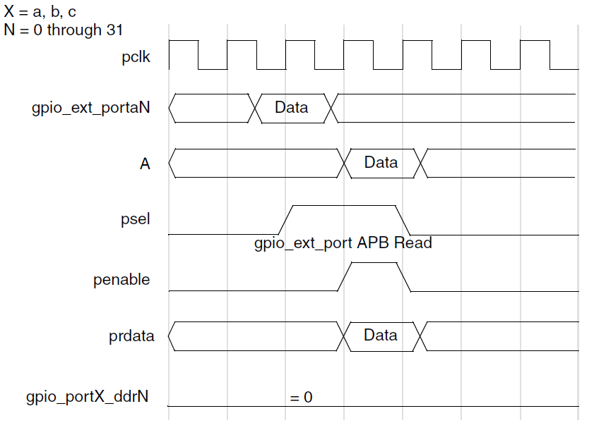
The following figure shows a timing diagram of a read to the GPIO_EXT_PORT memory map registers when the direction is set to input and the metastability registers are included, which brings a data delay of the port line.
Note
The maximum data rate that can be read back on consecutive reads from GPIO_EXT_PORT must be less than PCLK/2. Two pclk cycles per read access is required due to the non-pipelined nature of the APB. The assumption is that the APB bridge does not lose ownership of the AHB during consecutive accesses when PCLK=HCLK.
Direct Pad Input Selection
Not supported.
Not supported.
Not supported.
Not supported.
Not supported.
Not supported.
Not supported.
Not supported.
Not supported.
Interrupts
The GPIO peripheral supports configurable interrupt sources on any GPIO pin, with programmable interrupt types:
Edge-triggered interrupts: Rising edge, falling edge, or both edges
Level-sensitive interrupts: Active-high or active-low level
Interrupt masking is implemented through the GPIO_INT_MASK register, providing both masked (GPIO_INT_STATUS) and raw (GPIO_INT_STATUS_RAW) interrupt status information. Interrupt configuration requires the GPIO port data direction to be set as Input. Reprogramming the direction to Output preserves pending interrupts but prevents new interrupt generation.
The following figure illustrates the interrupt generation and data flow, showing two possible output architectures:
Individual Interrupt Mode: Separate signals (gpio_intr[N] or gpio_intr_n[N])
Combined Interrupt Mode: Single unified signal (gpio_intr_flag or gpio_intr_flag_n)
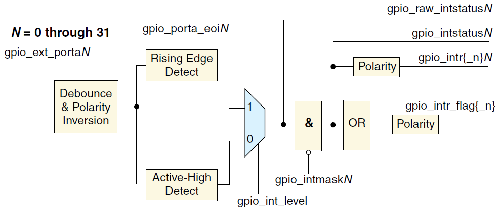
Interrupt RTL block diagram
In combined mode, the interrupt signal is generated by logically ORing all individual interrupt lines. This chip implements the combined interrupt architecture. Each GPIO port has one dedicated IRQ number in the system interrupt controller. Due to the combined interrupt implementation, the Interrupt Service Routine (ISR) must read the GPIO_INT_STATUS register to identify which GPIO pin(s) triggered the interrupt. The processor is responsible for interrupt prioritization and handling through software.
Interrupt Synchronization
Interrupt signals can be internally synchronized to a dedicated system clock, pclk_intr, with synchronization requirements determined by the interrupt type:
Edge-sensitive interrupts: Synchronization to pclk_intr is required. Edge-detected interrupt signals delivered to the processor are guaranteed to be synchronous with the system bus clock.
Level-sensitive interrupts: Synchronization to pclk_intr is optional and configurable through the GPIO_INT_LS_SYNC register by software.
The pclk_intr signal serves a critical role in power-managed systems. If the system requires interrupt detection capability even when the GPIO pclk is gated off, then pclk_intr must be provided. It is assumed that pclk_intr operates synchronously with pclk. Conversely, if interrupt detection is only required when pclk is running, both pclk_intr and pclk can be connected to the same clock source.
Edge-Sensitive Interrupt
Edge-sensitive interrupts are cleared by writing to the GPIO_INT_EOI register, which simultaneously clears both interrupt and raw status registers. Clearing the interrupt source before writing to GPIO_INT_EOI is recommended. This register has no effect on level-sensitive interrupts. In combined interrupt configurations, multiple edge-detected interrupts can be cleared simultaneously.
Single Edge Detection
The following figure shows an RTL diagram of the synchronization and edge detection of interrupt sources on gpio_ext_portaN signals, when GPIO_INT_BOTHEDGE = 0.
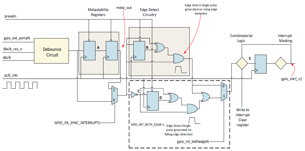
Synchronization and edge detect interrupt generation (GPIO_INT_BOTHEDGE = 0)
Note
Metastability part is default included.
Figure GPIO interrupt metastable shows a timing diagram in which an interrupt is generated on the rising edge of input on Port A; this is where the debounce logic is disabled and metastability registers are included. It also shows how an interrupt is cleared by a write to the interrupt clear register.
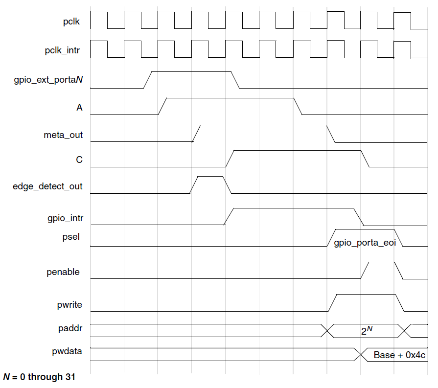
Interrupt edge detection and interrupt clear timing (GPIO_SYNC_PA_INTERRUPTS = 1, metastability included)
The ISR may write to the interrupt clear register to clear an existing interrupt during the same clock cycle in which a new interrupt is detected. In this case, only the first interrupt is cleared; setting an interrupt takes priority over clearing it within the same cycle, so the new interrupt is not lost.
Figure GPIO interrupt stable shows a timing diagram similar to the figure Figure GPIO interrupt metastable except that metastability registers are removed. It also shows how an interrupt is cleared by a write to the interrupt clear register.
Note
Since the Metastability registers are removed from the path, A and B waveforms, shown in Figure GPIO interrupt metastable, no longer exist, and all subsequent signal delays are reduced by two clock cycles.
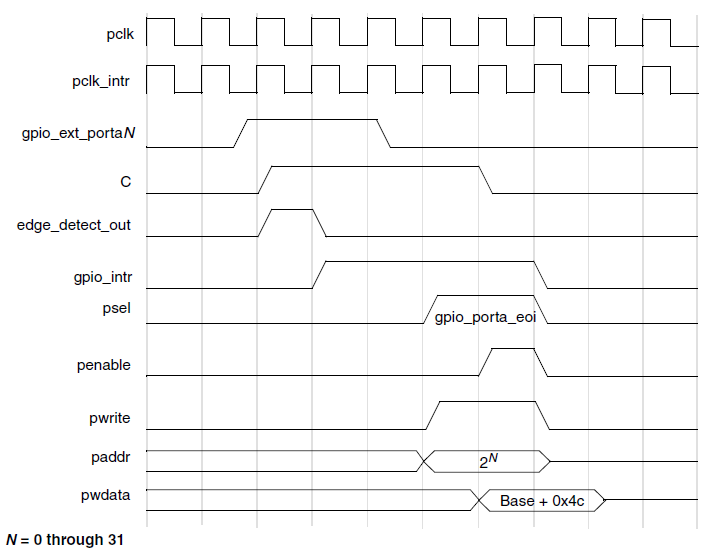
Interrupt edge detection and interrupt clear timing (GPIO_SYNC_PA_INTERRUPTS = 0, metastability removed)
The following figure shows such a case where the debounce logic is unused. In this timing diagram, meta_out and edge_detect_out are the outputs of the second metastability register and the edge detect logic, respectively. The second edge detection occurs on the same cycle as the write to the interrupt clear register. In this example, the write to the interrupt clear register does not clear the second interrupt, and the gpio_intr{_n} signal is not de-asserted.
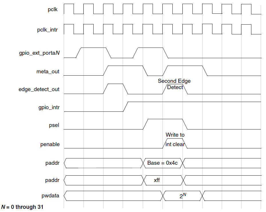
Write to interrupt clear register, coincident with detection of new interrupt
Dual Edge Detection
Interrupt detection logic for both the rising edge and the falling edge is available only when the GPIO_INT_BOTHEDGE register is programmed to 1 and this logic detects the interrupt on both the rising edge and the falling edge.
The following figure shows the synchronization and edge detect interrupt generation of the interrupt sources on gpio_ext_portaN signals.
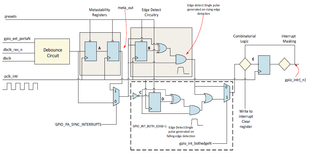
Synchronization and edge detect interrupt generation (GPIO_INT_BOTHEDGE = 1)
The following figure shows a timing diagram where an interrupt is generated on both the rising edge and the falling edge of input on Port A, that is, with GPIO_INT_BOTHEDGE = 1 programmed to detect both edges.
In this scenario, debounce logic is disabled and metastability registers are included. This figure also shows how an interrupt is cleared by a write to the interrupt clear register.

Interrupt edge detection and interrupt clear timing (GPIO_SYNC_PA_INTERRUPTS = 1 and GPIO_INT_BOTHEDGE = 1, metastability included)
The following figure shows a timing diagram similar to the figure Figure interrupt_metastability_included, except that in this scenario, metastability registers are removed.
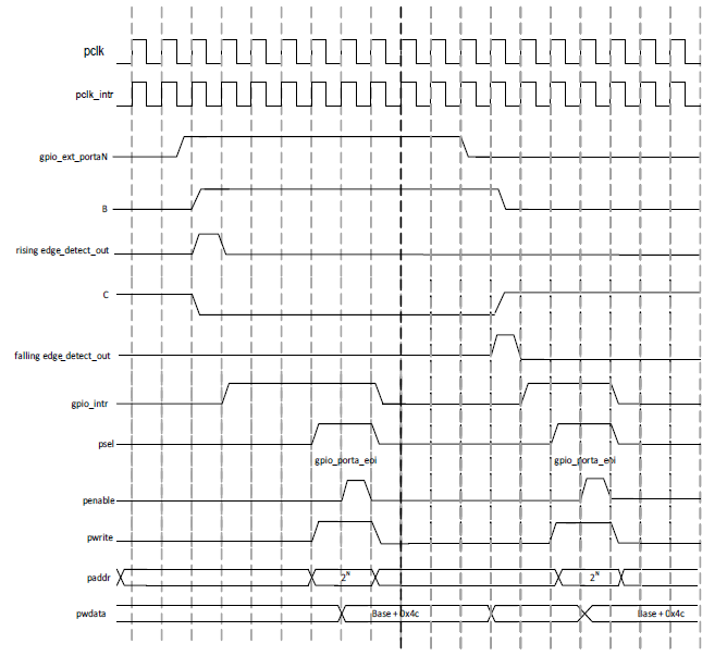
Interrupt edge detection and interrupt clear timing (GPIO_SYNC_PA_INTERRUPTS = 0 and GPIO_INT_BOTHEDGE = 1, metastability removed)
Level-Sensitive Interrupt
A level-sensitive interrupt triggers repeatedly until the source condition is cleared, so it requires proper ISR handling: the ISR can either poll the GPIO_INT_STATUS_RAW register until the interrupt source clears or mask the interrupt via GPIO_INT_MASK before exiting.
The following figure shows the generation of level-sensitive interrupts. As well, the debounce circuit below is an example of debouncing or removing spurious glitches narrower than one debounce clock (dbclk) period.
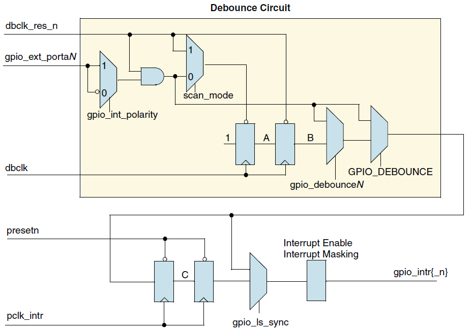
Level-sensitive interrupt RTL diagram
With level-sensitive interrupts, there is a choice of whether they are synchronized to the interrupt clock pclk_intr or are entirely combinational (aside from the debounce circuit).
The selection is done by programming the GPIO_INT_LS_SYNC (GPIO Level-Sensitive Synchronous) register.
This is a memory-mapped bit that inserts two metastability registers clocked off of pclk_intr to synchronize the level-sensitive interrupts to pclk_intr.
When GPIO_INT_LS_SYNC is not asserted, there is no guarantee that the interrupt lines are synchronous to pclk_intr. A processor status register may need to be set to indicate asynchronous interrupts. When GPIO_INT_LS_SYNC is asserted, the pclk_intr clock must be present to pass the interrupt to the interrupt controller block.
The gpio_intrclk_en output signal is asserted when level-sensitive interrupts are selected for synchronization to pclk_intr. The gpio_intrclk_en signal can be used in the clock generation block to turn on pclk_intr.
Note
In active mode, synchronizing pclk_intr to pclk is recommended to prevent circuit burrs.
In sleep mode, disabling this synchronization allows faster wake-up if required.
The following figure shows the generation of an active-low level-sensitive interrupt where the debounce circuitry is disabled.
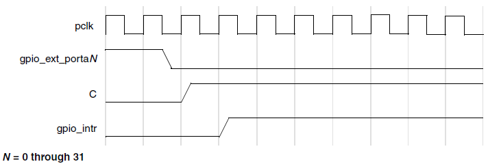
Active-low level-sensitive interrupt generation timing
Debounce Operation
If the user has configured the interrupt feature, GPIO can be configured to either include or exclude a debounce capability using the GPIO_DEBOUNCE parameter. The external signal can be debounced to remove spurious glitches narrower than one debounce clock (dbclk) period.
The following figure shows an RTL diagram of the debounce circuitry. The timing diagram shows an active-high input signal on gpio_ext_portxN. The polarity of the input signal detection is controlled by the memory-mapped signal, gpio_int_polarity. For a falling-edge or active-low-sensitive input, the input is then inverted and the same debounce logic is used as for rising-edge or active-high level-sensitive interrupts.
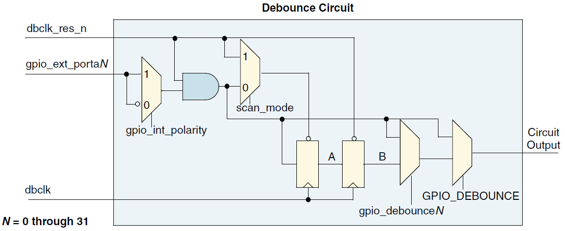
Debounce RTL diagram
dbclk_res_n signal is asynchronously asserted and synchronously de-asserted to the debounce clock, dbclk.
presetn, the system reset signal, is asynchronously asserted and synchronously de-asserted to pclk; synchronization must be external to the component.
The pclk and dbclk signals are assumed to be asynchronous to each other.
When input interrupt signals are debounced using a debounce clock, the signals must be active for a minimum of two cycles of the debounce clock to guarantee that they are registered. Any input pulse widths less than a debounce clock period are bounced. A pulse width between one and two debounce clock widths may or may not propagate, depending on its phase relationship to the debounce clock. If the input pulse spans two rising edges of the debounce clock, it is registered. If it spans only one rising edge, it is not registered.
The timing diagram below shows both cases: the input signal being bounced, and later, a propagated input signal. If GPIO supports debounce, then debouncing input signals on Port A can be enabled or disabled under software control.
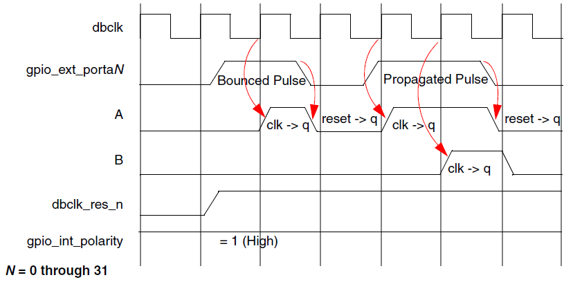
Debounce timing with asynchronous reset flip-flops
Note
The use of the debounce circuitry increases interrupt latency by two clock cycles of the debounce clock.
The debounce circuitry works with only asynchronous reset flip-flops.
Programming Considerations
Programming the GPIO registers for interrupt capability, edge-sensitive or level-sensitive interrupts, and interrupt polarity should be completed prior to enabling the interrupts on Portx to prevent spurious glitches on the interrupt lines to the interrupt controller.
If using external debounce function to remove spurious glitches, unexpected interrupts may be sent to the interrupt controller when enabling the interrupts.
To avoid unexpected interrupt with debounce circuit while re-configure the interrupt trigger mode, you had better wait the debounce time before enabling interrupt again.
Writing to the interrupt clear register clears an edge-detected interrupt and has no effect on a level-sensitive interrupt.
When reading back registers that are no longer present due to configuration parameters settings, 0 is read back. For example, if
APB_DATA_WIDTH = 32 bitsandGPIO_PWIDTH_A = 8, then the top 24 bits read back 0.

