Introduction
This chip integrates an IEEE 802.3-compliant Ethernet Media Access Control (MAC) controller. The MAC connects to an external Physical Layer (PHY) chip through a Reduced Media Independent Interface (RMII), and configures and manages the PHY through a Serial Management Interface (SMI).
The MAC is responsible for frame encapsulation and parsing, Cyclic Redundancy Check (CRC) generation and verification, flow control, and data transfer between the descriptors and memory.
Features
Interface and Speed
Supports the RMII interface.
Supports 10/100 Mbps speeds, in both full-duplex and half-duplex modes.
Supports access to PHY registers through the SMI (MDC/MDIO) interface, with the MAC acting as the SMI master.
Supports automatic polling of PHY registers to obtain the link status.
Operating Mode and Clock
Supports both MAC to PHY and MAC to MAC connections.
Supports a 50 MHz clock generated by dividing the on-chip PLL, or a 50 MHz clock input from the EXTCLK pin.
Supports outputting a 25 MHz or 50 MHz clock to the PHY through the EXTCLK pin.
Frame Processing
Supports IEEE 802.3x flow control in full-duplex mode and the CSMA/CD protocol in half-duplex mode.
In the TX direction, hardware automatically pads frames to the minimum frame length and decides whether to append a CRC according to the CRC bit in the descriptor.
In the RX direction, hardware verifies the CRC and supports checksum checking for the IPv4 header, TCP, and UDP. In the TX direction, hardware supports automatic checksum insertion for the IPv4 header, TCP, and UDP.
Supports receiving Jumbo Frames.
Supports destination address filtering of received frames (unicast, multicast, broadcast, and promiscuous mode).
Supports hardware processing of VLAN tags: insertion, removal, and re-tagging in the TX direction, and stripping in the RX direction.
Data Transfer and Interrupts
Exchanges data with memory through Descriptor Rings, with one Descriptor Ring each for TX and RX.
Provides interrupts for TX done, RX done, descriptor exhaustion, and RX FIFO overflow, and supports RX interrupt mitigation.
Provides TX and RX statistics counters.
Power Saving and Testing
Supports Energy Efficient Ethernet (EEE).
Supports MAC loopback mode.
Block Diagram
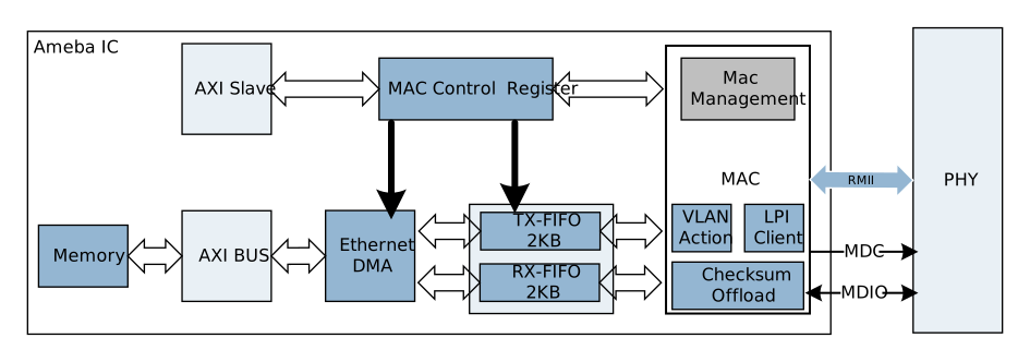
The following figure shows the architecture of the Ethernet module, which includes the AXI slave interface, MAC control registers, Ethernet DMA, TX/RX FIFOs, checksum offload, VLAN processing, the LPI client, and MAC management.
Ethernet architecture diagram
AXI slave interface and MAC control registers: The CPU accesses the MAC control registers through the AXI slave interface to configure the mode, filtering, flow control, interrupts, and so on.
Ethernet DMA: Reads transmit descriptors and data over the AXI bus and writes received data to memory. For details, see Descriptors and DMA.
TX-FIFO / RX-FIFO: The transmit and receive directions each have a FIFO of up to 2 KB, which buffers data between the DMA and the RMII interface.
Checksum offload: In the receive direction, verifies the IPv4 header, TCP, and UDP checksums. In the transmit direction, fills in the checksums automatically.
VLAN processing: In the transmit direction, inserts, removes, or re-tags VLAN tags. In the receive direction, strips VLAN tags.
LPI client: Asserts a Low Power Idle (LPI) request based on the state of the transmit queue, for use with EEE.
MAC management: Accesses the PHY registers through MDC/MDIO.
During transmission, software places the data to be sent into a buffer and sets up the descriptor. The Ethernet DMA reads the data from memory and passes it through the transmit FIFO to the MAC, which then sends it to the PHY through the RMII interface. During reception, the MAC receives data from the RMII interface and passes it through the receive FIFO to the Ethernet DMA. The DMA writes the data to a buffer in memory and writes back the length and status to the descriptor.

