Functional Description
This section describes the functions of the Ethernet MAC.
Interface
The MAC connects to the external PHY through two interfaces: RMII, which carries data, and SMI (MDC/MDIO), which is used to configure and manage the PHY.
RMII Data Interface
RMII reduces the 4-bit data bus of MII to 2 bits, at the cost of raising the REF_CLK frequency from 25 MHz to 50 MHz to maintain the 100 Mbps bandwidth.
Signal |
Abbreviation |
Direction |
Description |
|---|---|---|---|
TX Data 0/1 |
TXD0/TXD1 |
MAC → PHY |
Transmit data, 2 bits wide, with TXD0 as the least significant bit. At 100 Mbps, one 2-bit group is transferred per |
TX Enable |
TX_EN |
MAC → PHY |
Transmit enable. A high level indicates that the TXD data is valid. |
RX Data 0/1 |
RXD0/RXD1 |
PHY → MAC |
Receive data, 2 bits wide, with RXD0 as the least significant bit. At 100 Mbps, one 2-bit group is transferred per |
RX Error |
RX_ERR |
PHY → MAC |
Receive error indication. It is driven high when the PHY detects an error in the received frame (such as a coding error). |
CRS_DV |
CRS_DV |
PHY → MAC |
Composite signal of Carrier Sense and Data Valid. The MAC decodes the two states from this signal according to the RMII rules. |
Reference Clock |
REF_CLK |
Input or output |
50 MHz reference clock, which the MAC and PHY use to synchronize data transmit and receive. Its direction is determined by the selected clock scheme, and it can be driven by only one side. For details, see Clock. |
Note
IEEE 802.3u defines the RX_ERR signal. In practice, the MAC may leave this signal unused and rely solely on the Frame Check Sequence (FCS) carried in the Ethernet frame to verify data integrity.
SMI Management Interface
SMI, also known as the MDIO interface, is a two-wire serial interface for exchanging management data between the Ethernet MAC and the PHY, with a maximum clock frequency of 2.5 MHz. The MAC acts as the Station Management Entity (STA) and is the bus master, responsible for initiating read/write frames and driving the MDC clock; the PHY is the bus slave and responds to read/write requests from the STA.
Signal |
Abbreviation |
Direction |
Description |
|---|---|---|---|
Management Data Clock |
MDC |
MAC → PHY |
Management data clock, which provides the clock reference for MDIO data transfers, up to 2.5 MHz. |
Management Data Input/Output |
MDIO |
Bidirectional |
Management data line, which carries commands and status data. An external pull-up is required. |
MDC is not required to be a continuous periodic signal, and the STA may stop MDC between two frames. MDC can run at any lower frequency as long as it does not exceed the maximum frequency.
The MAC supports automatic polling of the PHY status through MDIO, which is controlled by the DISABLE_AUTO_POLLING bit of the MIIAR register: when this bit is 0, the hardware automatically polls the PHY status and reflects the link, duplex, and auto-negotiation complete status in the LINKB, FULLDUPREG, and NWCOMPLETE bits of the MSR register; when this bit is 1, the hardware no longer polls.
Clock
RMII data sampling relies on the 50 MHz REF_CLK. The MAC and PHY must use the same REF_CLK, and REF_CLK can be driven by only one side. The internal operating clock of the MAC and the REF_CLK used for RMII sampling are different concepts; their sources and the direction of REF_CLK must be configured separately according to the selected clock scheme. If both sides each generate a 50 MHz REF_CLK from an independent crystal, the frequency offset (PPM) between them causes sampling-point drift and results in CRC errors.
The REFCLK_ON bit of the MSR register controls whether the MAC drives REF_CLK: set it to 1 when the MAC provides REF_CLK, and clear it to 0 when REF_CLK is provided by the PHY or an external clock source. This bit is not the selection bit for the source of the internal operating clock of the MAC.
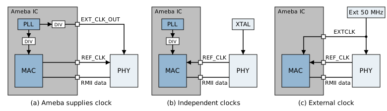
Clock architecture of the MAC and PHY
The 50 MHz clock of the MAC has two possible sources:
Internal clock source: The 50 MHz clock is derived by dividing the PLL inside this chip. The system clock configuration must be able to produce 50 MHz.
External clock source: The 50 MHz clock is input from the EXTCLK pin, and the MAC does not use internal division in this case.
The direction of REF_CLK depends on the clock source of the PHY:
Scheme |
MAC clock source |
PHY clock source |
REF_CLK direction (MAC side) |
EXTCLK pin |
|---|---|---|---|---|
Ameba provides 50 MHz |
Internal |
Ameba outputs 50 MHz |
Output |
Output clock |
Ameba provides 25 MHz |
Internal |
Ameba outputs 25 MHz |
Output |
Output clock |
Independent clock sources for MAC and PHY |
Internal |
PHY’s own crystal |
Input |
Not used |
External clock source |
External |
External 50 MHz clock source (same source as the MAC) |
Input |
Input clock |
For the selection criteria and board-level wiring of each scheme, refer to the Ethernet application note.
Note
The EXTCLK pin can be used either as an output or as an input, but not both at the same time. When switching to the external clock source, the external clock must reach the EXTCLK pin before the clock selection is switched, otherwise the MAC loses its clock.
Operating Mode
The RMII interface of the MAC supports two connection modes: MAC to PHY and MAC to MAC.
MAC to PHY
MAC to PHY is the default connection mode, in which the MAC connects to an external PHY chip. In this mode, the RMII interface follows the standard MAC definition: the MAC drives the TX signal lines and manages the external PHY through the MDC/MDIO interface.
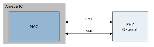
MAC connected to an external PHY chip
MAC to MAC
MAC to MAC is used to connect two chips that each have a MAC directly, without an external PHY chip.
In the traditional connection, two PHY chips are required between the two MACs (the extra components inside the dashed box in figure (a)). In MAC to MAC mode, the local MAC plays the PHY-side role on the RMII interface and connects directly to the MAC of the link partner, which eliminates these components (figure (b)):
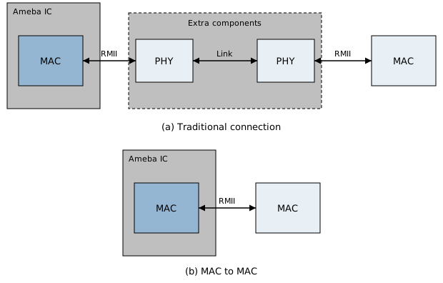
Traditional connection and MAC to MAC
Note the following in MAC to MAC mode:
No PHY chip is involved, so Auto-Negotiation cannot be performed. The speed and duplex mode must be forced, and the configurations of both ends must be identical.
The transmit and receive signals of the two ends must be cross-connected, that is, the TX of one end connects to the RX of the link partner.
The
REF_CLKof the two ends must come from the same source. It is recommended that one end output 50 MHz to the other end, or that both ends share the same external clock source, to avoid data sampling errors caused by a clock frequency deviation between the two ends.
Auto-Negotiation
Auto-Negotiation allows the devices at both ends of a link to exchange capability information and automatically select the same operating parameters, including duplex mode, speed, and flow control capability. After negotiation completes, both ends lock to the same duplex mode and speed. Auto-Negotiation is performed by the PHY in accordance with IEEE 802.3, and the MAC reads the negotiation result through SMI.
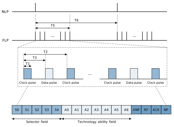
Link pulse and link code word
Auto-Negotiation conveys information through pulses on the link:
Normal Link Pulse (NLP): used for 10BASE-T. It is only used to detect whether the link is connected and carries no speed information.
Fast Link Pulse (FLP): used for 100BASE-TX. It extends the NLP into a pulse burst, and each burst carries a 16-bit link code word that advertises the speed and duplex capabilities.
Parallel Detection
When one end has Auto-Negotiation enabled and the other end does not support it or has it disabled (forced mode), the end with Auto-Negotiation enabled establishes the link through parallel detection:
If an NLP is detected, the link partner is determined to be a 10 Mbps device.
If an idle stream with 4B/5B encoding is detected, the link partner is determined to be a 100 Mbps device.
Warning
Parallel detection cannot obtain the duplex mode of the link partner, so the end with Auto-Negotiation enabled treats it as half-duplex as specified by the standard. If the link partner is forced to full-duplex, the duplex modes of the two ends do not match (duplex mismatch). Although the link appears to be up, collisions and CRC errors occur, along with severe packet loss.
Negotiation Results
Local configuration |
Link partner configuration |
Link result |
Description |
|---|---|---|---|
Auto-Negotiation |
Auto-Negotiation |
Success |
Both ends exchange capability sets and lock to the highest-performance mode supported by both, for example 100 Mbps full-duplex. |
Auto-Negotiation |
Forced 10/100 Mbps half-duplex |
Success |
Parallel detection is triggered. The local end matches the speed and is set to half-duplex. |
Auto-Negotiation |
Forced 10/100 Mbps full-duplex |
Duplex mismatch |
The link is up, but the local end is set to half-duplex by parallel detection while the link partner is full-duplex, which causes collisions and CRC errors. |
Auto-Negotiation (full-duplex only) |
Auto-Negotiation (half-duplex only) |
Failure |
The capability sets of the two ends do not overlap, so the link cannot be established. |
Forced-speed mode A |
Forced-speed mode B |
Different speeds: failure; same speed, different duplex: duplex mismatch |
With different speeds, the physical layer cannot synchronize and the link goes down. With the same speed but different duplex modes, the link may be up, but collisions and CRC errors occur, causing severe packet loss. |
Forced Mode
After Auto-Negotiation is disabled, the speed and duplex mode must be forced, and the PHY and MAC configurations must match, that is, the PHY side must also be forced accordingly. The MAC side forces the speed and duplex through the MSR register:
When
FORCE_SPD_MODEis set to 1, the MAC operates in forced speed mode, and the speed is set by theFORCE_SPDfield:00indicates 100 Mbps,01indicates 10 Mbps, and11indicates that the speed is not forced. WhenFORCE_SPD_MODEis 0, the speed comes from the MDIO auto-polling result.When
FORCEDFULLDUPis set to 1, the MAC is forced to operate in full-duplex mode. When it is 0, the duplex state comes from the MDIO auto-polling result.
A MAC to MAC connection has no PHY involved, so the forced configuration must be used.
Reading Status
The link and negotiation status can be read from the MSR register. The following are read-only status bits:
Bit |
Description |
|---|---|
LINKB |
Inverted link status. 0 indicates that the link is up, and 1 indicates that the link is down. |
NWCOMPLETE |
Auto-Negotiation is complete. |
FULLDUPREG |
Duplex state from the MDIO result. 1 indicates full-duplex. |
When the link status changes, the LINKCHG bit of the ISR register is set.
Descriptors and DMA
The MAC exchanges data with memory through DMA. Software submits data buffers to the MAC through descriptors in memory. The address, length, and status of each buffer are recorded in its descriptor, and the DMA moves the data.
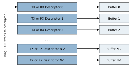
Descriptors and buffers
Descriptor Ring
Transmit and receive each have one descriptor ring, and each descriptor in a ring corresponds to one data buffer. The length of a descriptor is determined by the descriptor format. See “Descriptor Format” below.
The base address of the TX ring is set by the
TXFDP1register.The base address of the RX ring is set by the
RXFDP1register, and the number of descriptors in the ring is set by theRX_RINGSIZE1register. This register is in mask form, and its value is the number of descriptors minus 1. For example,0x00Findicates 16 descriptors. Therefore, the number of RX descriptors must be a power of 2, and the driver requires a value in the range of 4 to 4096. When reception of jumbo frames is enabled, the number of RX descriptors must not be less than 16.The
EORbit of the last descriptor in the ring is set to 1. After the hardware finishes processing this descriptor, it returns to the base address of the ring.The
TXCDO1andRXCDO1registers indicate the offset of the descriptor currently being processed by the hardware relative to the base address of the ring.
Note
This module supports only one TX descriptor ring and one RX descriptor ring, and does not support multiple descriptor rings. The registers related to descriptor rings numbered 2 and above (for example, TXFDP2 ~ TXFDP5 and RXFDP2 ~ RXFDP6) are not usable, and software does not need to configure them.
Descriptor Ownership
The OWN bit of each descriptor (bit31 of Word 0) indicates who currently processes the descriptor:
OWNis 1: The descriptor is owned by the DMA. For a TX descriptor, this means software has prepared the data to be transmitted. For an RX descriptor, this means software has allocated a free buffer. Software must not modify the descriptor at this time.OWNis 0: The descriptor is owned by the CPU. After the DMA completes the data transfer, it clears this bit, and software can reclaim the transmitted buffer or read the newly received data.
TX flow:
Software checks that
OWNof the current TX descriptor is 0, that is, the descriptor is available.Software fills in the data buffer address (Word 1), the length, and the control bits (Word 0).
Software sets
OWNto 1 to hand the descriptor over to the DMA.Software sets the
TXFN1STbit of theETH_ETHER_IO_CMDregister to 1 to notify the DMA to start transmitting.The DMA reads the data and transmits it, and clears
OWNwhen done.
Warning
The descriptor resides in normal memory, while TXFN1ST is a write to a device register, and the access order between the two is not guaranteed. A memory barrier (for example, the ARM dsb instruction) must be inserted after setting OWN and before writing TXFN1ST. Otherwise, the DMA may be woken up before it sees OWN.
RX flow:
Software writes
OWNand the buffer size into Word 0 of each RX descriptor, and writes the buffer address into Word 1.The MAC writes the received frame into the buffer, clears
OWNafter writing, and writes back the frame length and receive status in Word 0.Software detects that
OWNis 0 and reads the receive status and the data.Software rewrites
OWNand the buffer size to return the descriptor to the DMA.
When no free RX descriptors remain, the RDU1 bit of the ISR register is set and the MAC stops fetching RX descriptors. Reception resumes only after software releases descriptors and writes 1 to this bit to clear it.
The hardware requires the base address of the descriptor ring and the address of the RX buffer to be 4-byte aligned. If the descriptors and data buffers reside in cacheable memory, they must also be cache-line aligned, and software must ensure that the DMA and the CPU see consistent contents. For specific requirements, refer to the Ethernet application note.
When a frame occupies multiple descriptors, the descriptor with FS set is the first one of the frame, and the descriptor with LS set is the last one of the frame.
Descriptor Format
This module supports only the short descriptor in the Apollo format. A TX descriptor occupies 5 words (20 bytes) and an RX descriptor occupies 4 words (16 bytes). Their formats are shown in TX descriptor and RX descriptor, respectively.
During the use of a descriptor, software sets the command fields before submitting it. After the DMA finishes processing, in the receive direction the hardware writes back the frame length and receive status, while in the transmit direction all fields other than OWN remain unchanged. For the handover of ownership, see “Descriptor Ownership”.
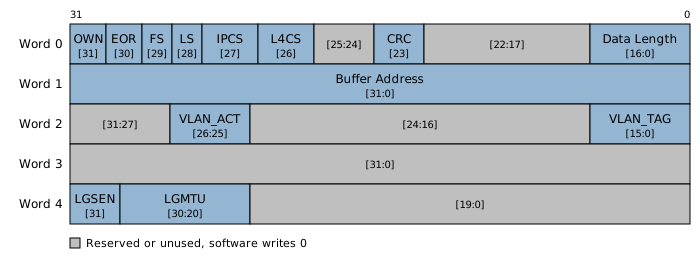
TX descriptor
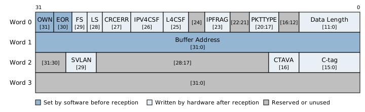
RX descriptor
TX Descriptor
The TX descriptor is a command descriptor, and software sets all of its fields before setting OWN. After transmission completes, the hardware only clears OWN and leaves the other fields unchanged. Software uses OWN to determine whether the descriptor can be reused.
Word |
Bits |
Name |
Description |
|---|---|---|---|
Word 0 |
[31] |
|
Ownership. 1 indicates the descriptor is owned by the DMA, and 0 indicates it is owned by the CPU. |
Word 0 |
[30] |
|
1 indicates that this descriptor is the last one in the ring. |
Word 0 |
[29] |
|
1 indicates that this descriptor contains the start of the frame. |
Word 0 |
[28] |
|
1 indicates that this descriptor contains the end of the frame. |
Word 0 |
[27] |
|
1 indicates that the hardware calculates the IPv4 header checksum. |
Word 0 |
[26] |
|
1 indicates that the hardware calculates the TCP/UDP checksum. When this bit is set, IPCS must also be set. |
Word 0 |
[23] |
|
1 indicates that the hardware appends the frame check sequence at the end of the frame. |
Word 0 |
[16:0] |
|
Number of valid bytes in the buffer pointed to by this descriptor. |
Word 1 |
[31:0] |
|
Start address of the buffer. |
Word 2 |
[26:25] |
|
VLAN tag action. See the VLAN section for details. |
Word 2 |
[15:0] |
|
Tag content used for insertion or retagging. |
Word 4 |
[31] |
|
1 indicates that the frame uses Large Send Offload (LSO), and the hardware automatically segments it according to |
Word 4 |
[30:20] |
|
IP total length of each frame after LSO segmentation, in bytes. See the LSO section for details. |
The gray bits in the figure are unused, and software writes 0 to them.
RX Descriptor
For an RX descriptor, OWN, EOR, the buffer address, and the buffer size are set by software before the descriptor is handed over to the DMA. After a frame is received, the MAC writes the frame into the buffer, clears OWN, and writes back the frame length and receive status. Software reads them after detecting that OWN is 0.
Word |
Bits |
Name |
Valid Timing |
Description |
|---|---|---|---|---|
Word 0 |
[31] |
|
Set before reception, cleared after reception |
Set to 1 before reception, indicating that the descriptor is owned by the DMA and its buffer is free. After a frame is received, the hardware clears it, indicating that the descriptor is owned by the CPU and data has been received. |
Word 0 |
[30] |
|
Set before reception |
1 indicates that this descriptor is the last one in the ring. |
Word 1 |
[31:0] |
|
Set before reception |
Start address of the buffer. |
Word 0 |
[29] |
|
Valid after reception |
1 indicates that this descriptor contains the start of the frame. |
Word 0 |
[28] |
|
Valid after reception |
1 indicates that this descriptor contains the end of the frame. |
Word 0 |
[27] |
|
Valid after reception |
1 indicates that the frame has a CRC error. Frames with CRC errors are received only when the AER bit of the RCR register is set to 1. |
Word 0 |
[26] |
|
Valid after reception |
1 indicates that the hardware detected an IPv4 header checksum error. This bit is valid only when |
Word 0 |
[25] |
|
Valid after reception |
1 indicates that the hardware detected a TCP/UDP/ICMP/IGMP checksum error. This bit is valid only when |
Word 0 |
[23] |
|
Valid after reception |
1 indicates that the frame is an IP fragment. |
Word 0 |
[20:17] |
|
Valid after reception |
Packet type. 0 indicates an Ethernet frame (neither IPv4 nor IPv6), 1 indicates IPv4, 2 indicates IPv4/PPTP, 3 indicates IPv4/ICMP, 4 indicates IPv4/IGMP, 5 indicates IPv4/TCP, 6 indicates IPv4/UDP, 7 indicates IPv6, 8 indicates ICMPv6, 9 indicates IPv6/TCP, and 0xA indicates IPv6/UDP. |
Word 0 |
[11:0] |
|
Set before reception, written back after reception |
Before reception, the buffer size in bytes is written. After reception completes, the hardware writes back the number of bytes actually received in this descriptor, including the 2-byte padding inserted by the MAC before the frame data. |
Word 2 |
[29] |
|
Valid after reception |
1 indicates that the frame carries an S-tag. |
Word 2 |
[16] |
|
Valid after reception |
1 indicates that the frame carries a C-tag and the tag has been stripped. |
The gray bits in the figure are unused. Software writes 0 to them when setting up the descriptor, and does not need to read them after reception completes.
Large Send Offload (LSO)
LSO allows software to submit a large frame that exceeds the Maximum Transmission Unit (MTU). The MAC hardware splits it into multiple frames according to the MTU, transmits them, and recalculates the IP header and checksum of each frame, which relieves the CPU of segmentation work. LSO applies only to the transmit direction.
The MAC supports splitting three types of large frames:
TCP: the TCP data is segmented, and the IP length of each segment does not exceed
LGMTU.UDP: the UDP datagram is fragmented according to the MTU, up to 64 KB.
Other protocols: the hardware performs IP fragmentation, and L4 checksum offload is not supported.
Enabling
For each frame that needs to be split, set LGSEN (bit31 of Word 4) to 1 in its transmit descriptor, and fill LGMTU into bit[30:20].
LGMTU is the MTU, that is, the IP length of a single frame including the L3 and L4 headers. It is not the TCP Maximum Segment Size (MSS). The MAC subtracts the L3 and L4 header lengths from LGMTU internally to obtain the MSS. Therefore, to obtain an MSS of 1448 (IPv4 plus TCP, with a total header length of 40 bytes), write 1488.
The LGMTU field is 11 bits wide and should be less than 0x680 (limited by the transmit FIFO capacity).
Note
Some documents (for example, the descriptor table in the register specification and the driver header files) call this field LGMSS. Its meaning is still the MTU, not the MSS. Filling in the MSS makes the total IP length of each segment shorter by the length of the L3 and L4 headers.
Data Format Requirements
The data in the transmit buffer must be in one of the following formats:
DA + SA + C-tag + Type + IP + L4 (TCP or UDP)
DA + SA + Type + IP + L4 (TCP or UDP)
DA + SA + C-tag + Type + IP
DA + SA + Type + IP
The requirements for the checksum offload bits in the transmit descriptor depend on the protocol:
TCP: both
IPCSandL4CSmust be set.UDP:
L4CSis optional. When it is set, the hardware calculates the UDP checksum of the entire datagram; clear it when the UDP checksum is not used.Other protocols: the hardware only performs IP fragmentation and does not support L4 checksum offload, so
L4CSmust not be set.
LSO does not support frames that carry an S-tag.
TCP Restrictions
The MTU of a single frame must not be greater than the MSS plus the L3 and L4 header lengths; otherwise LSO cannot work, because the hardware no longer performs IP fragmentation automatically.
In the large frame, the MF flag and fragment offset of the IP header, as well as the URG, RST and SYN flags and the urgent pointer of the TCP header, must all be 0.
TCP retransmission, congestion control and flow control (sliding window) are not supported.
When a frame occupies multiple transmit descriptors, the DA, SA, Type, IP header and TCP header must be in the same descriptor.
UDP Restrictions
Only the first of the split frames carries the UDP header; the remaining frames carry data only.
After splitting, the MF flag in the IP header of every frame except the last one is set, and their total length equals the MTU; the total length of the last frame is the remaining data length plus the IP header length. The IP header checksum of each frame is recalculated by the hardware.
The UDP checksum of the first frame is the checksum of the entire datagram.
The transmit descriptors can be submitted in either of the following two ways: descriptor 0 contains only the L2/L3/L4 headers and descriptor 1 contains only the L4 data; or descriptor 0 contains the headers and part of the L4 data, in which case Data Length must be greater than the header length plus
LGMTU, and descriptor 1 contains the remaining L4 data.
Interrupts and Counters
The interrupt status of the MAC is indicated by the ISR register, and interrupt masking is controlled by the IMR register. The bits of the two registers correspond one to one. When the corresponding bit in IMR is 1, setting that bit in ISR generates an interrupt to the CPU.
All bits of ISR are cleared by writing 1.
Warning
When clearing ISR, write the bits to be cleared directly. Do not use read-modify-write (for example, ISR |= x). A read-modify-write writes back all pending bits that were read, which clears other interrupts that have not yet been handled at the same time.
Interrupt Sources
Bit |
Name |
Description |
|---|---|---|
0 |
ROK |
Receive complete. Set when the number of received frames reaches the count configured for RX interrupt mitigation, or when the RX timer expires. For frames smaller than 128 bytes, it is set immediately after DMA completes. |
1 |
CNT_WRAP |
TX or RX counter wraparound. |
2 |
RER_RUNT |
A runt frame shorter than 64 bytes was received. |
4 |
RER_OVF |
RX FIFO overflow. Possible causes are running out of free RX descriptors, insufficient system bus performance, or bus traffic overload. |
5 |
RDU1 |
RX descriptor unavailable. |
6 |
TOK_TI |
Transmit complete. Set when the number of transmitted frames reaches the count configured for TX interrupt mitigation and the last descriptor has been processed. |
7 |
TER |
Transmit error. The transmission was aborted due to excessive collisions. |
8 |
LINKCHG |
Link status change. |
9 |
TDU |
TX descriptor unavailable. |
10 |
SWINT |
Software interrupt. Writing 1 to bit24 of the SWINT register forces this bit to be set. |
The remaining bits are reserved and not used.
After RDU1 is set, the MAC stops fetching RX descriptors. Reception resumes only after software releases RX descriptors and writes 1 to RDU1 to clear it.
Interrupt Mitigation
To reduce the number of interrupts, both TX and RX interrupts support mitigation: an interrupt is generated only after the configured number of frames has accumulated. A timer is also provided so that an interrupt is still generated in time when fewer frames than configured have accumulated. These parameters are located in the ETH_ETHER_IO_CMD register.
Field |
Description |
|---|---|
RXINTMITIGATION |
Number of frames that must be received before a ROK interrupt is generated. A value of 0 corresponds to 1 frame. Starting from a value of 1, each increment of 1 adds 4 frames, that is, 4, 8, 12, 16, 20, 24, and 28 frames. |
TXINTMITIGATION |
Number of frames that must be transmitted before a TOK_TI interrupt is generated. The values are the same as those of RXINTMITIGATION. |
RXPKTTIMER |
RX timer. When set, a ROK interrupt is generated when the timer expires, even if the number of received frames has not reached the mitigation count. A value of 0 means the timer is not used. This timer takes effect only for frames larger than 128 bytes. For frames smaller than 128 bytes, ROK is triggered immediately after DMA completes. |
TXPKTTIMER |
TX timer, which works similarly to RXPKTTIMER. |
INT_TIMER_SEL |
Selects the unit of the timers. |
The timer unit depends on the link speed. At 100 Mbps, when INT_TIMER_SEL is 0, 1, 2, or 3, the unit is 2.56 μs, 10.24 μs, 40.96 μs, or 160 μs, respectively. At 10 Mbps, the units are 25.6 μs, 102.4 μs, 409.6 μs, and 1.6 ms, respectively. Timer interval = timer value × 4 × unit.
Statistics Counters
The MAC provides a set of 16-bit statistics counters. A counter wraps around automatically when it overflows, and writing to the register clears it. When any counter wraps around, the CNT_WRAP bit of ISR is set.
Counter |
Description |
|---|---|
RXOKCNT |
Number of frames received successfully. |
TXOKCNT |
Number of frames transmitted successfully. |
RXERR |
Number of frames discarded due to receive errors. When the RX FIFO is not full, this counter increments by 1 if the AR bit of RCR is 0 and the frame is shorter than 64 bytes, or if the AER bit is 0 and the frame has a CRC error. |
TXERR |
Number of frames with transmit errors, including transmit underflow, transmit abort in half-duplex mode, and link errors. |
FAE |
Number of frames with frame alignment errors. This counter counts only frames that are accepted, so the AER bit of RCR must be 1. Such frames do not increment RXERR. |
MISSPKT |
Number of missed frames. |
RDU_MISSPKTC |
Number of frames missed because RX descriptors were unavailable. |
TXMCOL |
Number of frames transmitted successfully after experiencing collisions, with fewer than 16 collisions (or the configured retry count). |
TX1COL |
Number of frames transmitted successfully after experiencing exactly one collision. |
TXABT |
Number of aborted transmissions. The causes include excessive collisions, underflow, and link failure. |
TXUNDERC |
Number of frames with transmit underflow. |
RXOKBRD |
Number of frames received successfully whose destination address is a broadcast address. |
RXOKPHY |
Number of frames received successfully whose destination address matches the local physical address. |
RXOKMUL |
Number of frames received successfully whose destination address is a multicast address. |
The AER bit of RCR controls how erroneous frames are handled:
AERis 1: Frames with CRC errors, alignment errors, or collision fragments are received and passed up. RXOKCNT increments by 1, RXERR is unchanged, and the CRCERR bit of the RX descriptor is set to 1.AERis 0: Such frames are discarded. RXERR increments by 1, and RXOKCNT is unchanged.
Flow Control
Flow control notifies the link partner to pause transmission before the RX buffer is exhausted, so as to avoid packet loss. The Ethernet MAC complies with IEEE 802.3x, takes effect only in full-duplex mode, and is implemented through PAUSE frames.
PAUSE Frames
A PAUSE frame is a MAC control frame. Its destination address is the reserved multicast address 01:80:C2:00:00:01, its Type field is 0x8808, and its opcode is 0x0001. It carries a 16-bit pause time in units of 512 bit times.
Pause time is not 0: notifies the link partner to pause transmission for the duration given by this time.
Pause time is 0: notifies the link partner to resume transmission immediately.
The pause time is in units of pause quanta. One pause quantum equals the time required to transmit 512 bits, so the actual duration depends on the link speed. When the pause time is the maximum value 0xFFFF, it is about 335.5 ms at 100 Mbps and about 3.355 s at 10 Mbps.
The PAUSE frames transmitted by the MAC are generated automatically by the hardware, and the pause time is not configurable. After the transmit PAUSE function is enabled, when the receive resources reach the pause threshold, the MAC transmits a PAUSE frame whose pause time is the maximum value 0xFFFF; when they reach the resume threshold, it transmits a PAUSE frame whose pause time is 0. For the meaning of the thresholds, see “Conditions for Transmitting PAUSE Frames”.
Transmit and Respond
The MAC supports both transmitting and responding to PAUSE frames, which are enabled by two bits of the MSR register respectively:
Bit |
Description |
|---|---|
TXFCE |
Enable transmitting PAUSE frames. When the RX buffer is about to be exhausted, the MAC transmits a PAUSE frame to the link partner. |
RXFCE |
Enable responding to PAUSE frames. After receiving a PAUSE frame from the link partner, the MAC pauses transmission; this bit takes effect only in full-duplex mode. |
When TXFCE is enabled, the AER bit (receive error frames) of the RCR register must not be enabled at the same time.
The MSR register provides two read-only status bits: RXPF set to 1 indicates that the MAC is in the pause (backoff) state because it received a PAUSE frame; TXPF set to 1 indicates that the MAC has transmitted a PAUSE frame, and 0 indicates that the most recently transmitted frame was a PAUSE frame with a pause time of 0 (the notification frame that ends the pause).
Auto-Negotiation and Forced Flow Control
The flow control capability is exchanged with the link partner through auto-negotiation.
Without auto-negotiation, flow control cannot be determined through negotiation. For example, the link partner has disabled auto-negotiation, or the local side forces the speed and duplex mode, or it works in MAC to MAC mode. In this case, setting only TXFCE or RXFCE of the MSR register to 1 does not take effect; FORCE_TRXFCE must also be set to 1 for flow control to work.
Conditions for Transmitting PAUSE Frames
Transmitting a PAUSE frame is triggered by the number of free RX descriptors. A free RX descriptor is a descriptor that software has returned to the MAC and that can be used to receive a new frame. Receiving a frame consumes one or more free descriptors, and the number of free descriptors rises again after software returns descriptors.
Both thresholds are expressed as a number of free RX descriptors:
RX_PSE_DES_THRES_ON: when the free descriptors drop to this number, the MAC asserts a pause request and transmits a PAUSE frame with a pause time of0xFFFFto the link partner.RX_PSE_DES_THRES_OFF: when the free descriptors rise back to this number, the MAC deasserts the pause request and transmits a PAUSE frame with a pause time of 0 to the link partner.
RX_PSE_DES_THRES_ON must be less than RX_PSE_DES_THRES_OFF.
For example, with 4 RX descriptors in total, RX_PSE_DES_THRES_ON set to 1 and RX_PSE_DES_THRES_OFF set to 2, as shown in the figure:
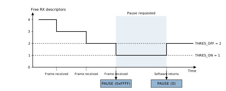
Timing of PAUSE frame transmission
When 2 free descriptors remain, the MAC does not assert a pause request. After another frame is received and one descriptor is consumed, 1 free descriptor remains; the MAC asserts a pause request and transmits a PAUSE frame with a pause time of
0xFFFF.After the link partner pauses transmission, software processes the data and returns descriptors, and the free descriptors rise back to 2; the MAC deasserts the pause request and transmits a PAUSE frame with a pause time of 0.
After software finishes processing the received data and returns the RX descriptors to the MAC, it must update the ETHRNTRXCPU_DES_NUM field to tell the MAC the number of descriptors that have been returned. The MAC uses this to calculate the number of free descriptors.
RX_PSE_DES_THRES_OFF must be less than the total number of RX descriptors minus the maximum number of descriptors occupied by a single ingress frame.
Note
When the AFLOW bit of the RCR register is set to 1, the MAC also delivers received PAUSE frames into the RX buffer as normal frames. This is for debugging only.
VLAN
The MAC supports hardware processing of IEEE 802.1Q VLAN tags. A VLAN tag is a 4-byte field inserted after the source address and before the type field of an Ethernet frame. An additional tag can be nested outside the tag (QinQ). The outer tag is called the S-tag, and the inner tag is called the C-tag.
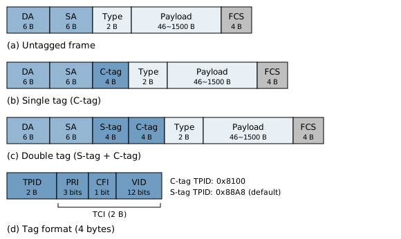
VLAN frame format
Hardware Limitations
A maximum of two tag layers (S-tag and C-tag) can be recognized. Nested tags with three or more layers are not supported.
In the transmit direction, only one action can be performed on one tag layer at a time.
In the receive direction, only the inner C-tag can be stripped.
Transmit Direction
VLAN processing in the transmit direction is specified frame by frame by the TX descriptor. The second word of the TX descriptor (Word 2) contains two VLAN-related fields:
Field |
Bits |
Description |
|---|---|---|
VLAN_ACT |
[26:25] |
The action performed on the VLAN tag of the frame. See the table below. |
VLAN_TAG |
[15:0] |
The 16-bit tag content used for insertion or re-tagging, including the VID, priority (PRI), and CFI. |
Values of VLAN_ACT:
Value |
Action |
Description |
|---|---|---|
00 |
Keep as is |
Does not modify the tags in the frame. |
01 |
Insert |
Inserts a new tag into the frame. The tag content is taken from VLAN_TAG. |
10 |
Remove |
Removes one specified tag from the frame. |
11 |
Re-tag |
Keeps the original tag structure and replaces only the VID. |
Whether the action applies to the S-tag or the C-tag is determined by the TDSC_VLAN_TYPE bit of the VLAN_REG register:
TDSC_VLAN_TYPEis 0: The action in the descriptor applies to the C-tag.TDSC_VLAN_TYPEis 1: The action in the descriptor applies to the S-tag.
S-tag Protocol Identifier
The TPID of the S-tag is set by the STAG_PID field of the VLAN_REG register, and its reset value is 0x88A8. The same value is used to identify the S-tag in both the transmit and receive directions. STAG_PID must not conflict with common EtherType values such as IPv4 and ARP. Otherwise, the type field in a frame is misidentified as an S-tag.
Receive Direction
When the RXVLAN bit of the ETH_CR register is 1, the MAC strips the inner C-tag from received frames and writes the stripped tag content into the RX status descriptor:
The
CTAVAbit of Word 2 in the RX status descriptor is set to 1, indicating that the frame carries a C-tag.The lower 16 bits of Word 2 hold the stripped tag content.
If the frame also carries an S-tag, the
SVLANbit is set to 1.
When a received frame occupies multiple descriptors, the VLAN information appears only in the last descriptor.
When RXVLAN is 0, the MAC does not strip tags. The tags in the frame remain in the received data, and CTAVA is 0.
Energy Efficient Ethernet (EEE)
EEE is based on IEEE 802.3az, and its core mechanism is LPI: after the link is established, if there is no data transfer, the device can enter a low-power state through protocol interaction to reduce power consumption.
EEE is implemented jointly by the MAC and the PHY:
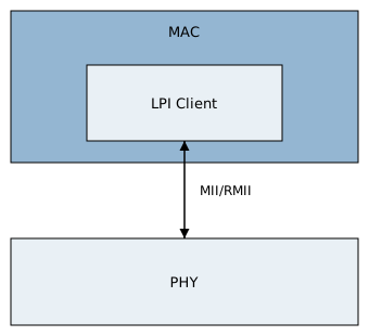
Energy Efficient Ethernet architecture
The LPI client is located in the MAC and initiates LPI requests according to the status of the transmit queue.
The PHY encodes the RMII signals and interacts with the link partner over the line.
Prerequisites for using EEE:
Auto-negotiation must be enabled. The EEE capability is exchanged with the link partner through the Next Page of auto-negotiation.
The link must operate in full-duplex mode.
Both the PHY and the link partner must support EEE.
LPI Signals on RMII
Standard RMII removes the TX_ER signal of MII, so the signal combinations of IEEE 802.3az cannot be used directly. RMII uses combinations of TX_EN, CRS_DV and the data lines to indicate entering and exiting LPI.
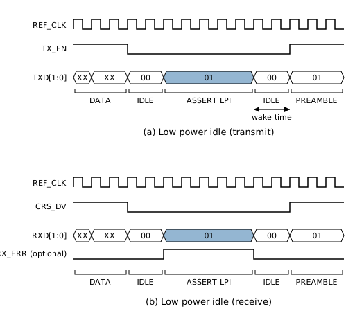
Entering and exiting LPI on the transmit and receive paths
The transmit path is controlled by the MAC, which decides when to make the PHY enter or exit the low-power state:
Enter LPI: the MAC drives
TX_EN=0andTXD=01. After detecting this state, the PHY turns off the analog transmit circuit.Stay in LPI: the MAC keeps
TX_EN=0andTXD=01.Exit LPI: the MAC restores
TXD[1:0]from01to00(TX_ENis still 0 at this point), which indicates a wake-up request. After the wake-up time elapses, the MAC drivesTX_ENhigh and starts transmitting data.
The receive path is controlled by the PHY, which detects the state of the link partner and notifies the MAC:
Enter LPI: after detecting the LPI signal of the link partner on the line, the PHY drives
CRS_DVlow and drivesRXD[1:0]to01. After detecting this state, the MAC enters the receive low-power state.Stay in LPI: the PHY keeps
RXD[1:0]at01until the line state changes.Exit LPI: after detecting an idle code stream or data on the line, the PHY restores
RXD[1:0]from01to00, and the MAC resumes receiving accordingly.
After the PHY detects an LPI request on the RMII interface, it goes through Sleep, Quiet, Refresh and Wake in sequence on the line:
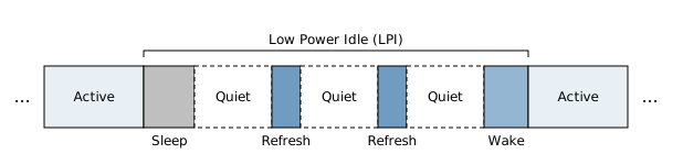
LPI states
Sleep: the local PHY transmits the SLEEP code group to notify the link partner.
Quiet: the PHY stops transmitting signals after transmitting SLEEP.
Refresh: refresh signals are transmitted periodically during the quiet period to maintain the link parameters.
Wake: the PHY transmits the wake-up signal to notify the link partner to resume normal operation.
Decision Logic of the Transmit Path
LPI on the receive path is determined by the PHY, and the MAC cooperates passively. Entering and exiting LPI on the transmit path are determined by the decision logic inside the MAC, which are enabled separately through bits of the EEE_CR1 register.
Decision logic for entering LPI:
Bit |
Decision condition |
|---|---|
EEE_REQ_SET0 |
By rate: requests to enter LPI when the transmit traffic within the statistics window T_tx_rate is lower than the threshold EEE_TX_THR. |
EEE_REQ_SET1 |
Requests to enter LPI when the transmit queue is empty. |
EEE_REQ_SET2 |
Requests to enter LPI when a PAUSE frame is received from the link partner. T_pause is the timing used by this decision logic. |
Decision logic for exiting LPI:
Bit |
Decision condition |
|---|---|
EEE_WAKE_SET0 |
Exits LPI when there is data to be transmitted in the transmit queue. |
EEE_WAKE_SET1 |
Exits LPI when a frame to be transmitted is larger than 512 bytes. |
When software has a large amount of data to be transmitted, it can set EEE_OUTQ_LOWQ_OVER to 1 to notify the hardware to exit LPI.
The EN_EEE_TX and EN_EEE_RX bits of EEE_CR1 enable the EEE capability in the transmit and receive directions respectively.
Timing Parameters
The timing parameters at 100 Mbps are located in the EEE_CR3 register:
Parameter |
Reset value |
Unit |
Description |
|---|---|---|---|
EEE_TIMER_TW_100 |
0x1E |
EEE_TIMER_UNIT_100_1 |
Wake-up time T_wakeup. This value should be no less than the wake-up time required by the PHY. |
EEE_TIMER_TR_100 |
0x0A |
EEE_TIMER_UNIT_100_1 |
Rate statistics window T_tx_rate. |
EEE_TIMER_TP_100 |
0x0A |
EEE_TIMER_UNIT_100_1 |
Timing T_pause used by the PAUSE decision logic. |
EEE_TIMER_TD_100 |
0xF4 |
EEE_TIMER_UNIT_100_2 × 4 |
QoS decision delay T_tx_delay. |
The table lists the reset value of each field. The actual time equals the field value multiplied by the corresponding unit.
Two fields in the EEE_CR1 register set the units of the above parameters:
EEE_TIMER_UNIT_100_1:00means 1 μs,01means 16 μs,10means 128 μs, and11means 1024 μs.EEE_TIMER_UNIT_100_2:00means 8 μs,01means 64 μs,10means 512 μs, and11means 1024 μs.
The rate threshold EEE_TX_THR_100 is located in the lower 16 bits of the EEE_CR4 register, in bytes, and is calculated as follows:
EEE_TX_THR = Round[(T_tx_rate × Rate) / 8]
For example, when T_tx_rate is 10 μs and the rate is 100 Mbps, the threshold is 0x7D (125 bytes), and the reset value is 0x3E, which is about half of the rate. A larger threshold makes it easier to enter LPI, and a smaller threshold makes it harder to enter LPI.
Status and Statistics
The EEE_CR1 register provides the following read-only status bits:
Bit |
Description |
|---|---|
EEE_TX_STS |
The transmit path is in LPI. |
EEE_RX_STS |
The receive path is in LPI. |
EEE_STS |
The transmit and receive paths are both in LPI. |
EEE_PAUSEFLAG |
An LPI request was initiated because a PAUSE frame was received. |
After the EEE_TXTIMER_EN and EEE_RXTIMER_EN bits of the EEE_CR1 register are enabled, the MAC accumulates the time that the transmit and receive paths spend in LPI respectively, in μs, and the accumulated value is 22 bits wide. The accumulated time of the transmit path is read from the EEE_TXLPI_TIME field of the EEE_LPI_TM1_REG register, and that of the receive path is read from the EEE_RXLPI_TIME field of the EEE_LPI_TMO_REG register. Both fields are cleared on read, and the count restarts from 0 after being read.
Loopback Test
The MAC provides loopback functions for driver development, interrupt testing and link connectivity verification. The loopback mode is selected by the LBK field of the TCR register.
LBK |
Mode |
Description |
|---|---|---|
00 |
Normal operation |
No loopback. |
01 |
R2T loopback |
Received data is sent directly back to the transmit path and transmitted as egress frames. |
10 |
Reserved |
Do not use. |
11 |
T2R loopback |
Transmitted data is sent back to the receive path inside the MAC. |
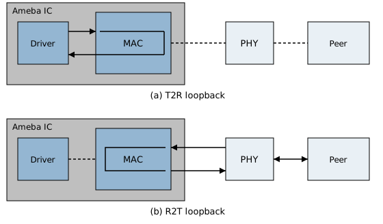
Loopback test modes
R2T Loopback
R2T loopback (Receive to Transmit) sends frames received from RMII back to the RMII transmit direction unchanged. It is used to verify the transmit and receive paths of the MAC from the link partner, without software moving the frames.
The data of R2T loopback does not pass through the transmit and receive FIFOs. Instead, it is passed between the receive clock domain and the transmit clock domain through an asynchronous FIFO. The receive clock comes from a pin, and the transmit clock is generated by the MAC itself. The two are independent of each other.
Note
Frames looped back in R2T loopback are counted in the successful receive counter RXOKCNT, not in the successful transmit counter TXOKCNT. Keep this in mind when using TXOKCNT to determine whether R2T loopback is working.
T2R Loopback
T2R loopback (Transmit to Receive) sends transmitted data back to the receive path inside the MAC. It is used to verify the transmit and receive logic of the MAC itself. The data path in this mode is: transmit buffer → transmit DMA and FIFO → MAC internal loopback → receive DMA → receive buffer.
In this mode, the recommended value of the RCR register is 0xF, that is, AAP, APM, AM and AB are set to 1, so that the MAC accepts frames with any destination address and the looped-back frames are not dropped by address filtering. During normal transmission and reception, RCR should be configured according to the address filtering policy.

