Functional Description
Coexistence Design
This chapter describes the managed coexistence mechanism of Ameba SoCs. It is based on
Packet Traffic Arbitration (PTA) hardware that grants RF access to transmissions on a per-packet basis
Time Division Multiple Access (TDMA) software that dynamically allocates time slots for prioritized continuous transmissions.
Ameba on-chip managed coexistence automatically adapts to the optimal strategy for the current scenario. Developers do not need to manually configure coexistence parameters or debug coexistence performance; they only need to focus on their own RF module application development.
PTA
Ameba series SoCs have a built-in PTA circuit that receives transmission requests from different module basebands in real time. After arbitration based on preset configurable priorities, it promptly feeds back grant results and simultaneously switches or connects the RF path to the baseband for transmission. The figure below illustrates the PTA circuit design: the external RF module represents an external Bluetooth or 802.15.4 chip for Ameba DualChip-Coex, while Wi-Fi, Bluetooth, and 802.15.4 represent Ameba SingleChip-Coex; 802.15.4 is supported in select Ameba models.
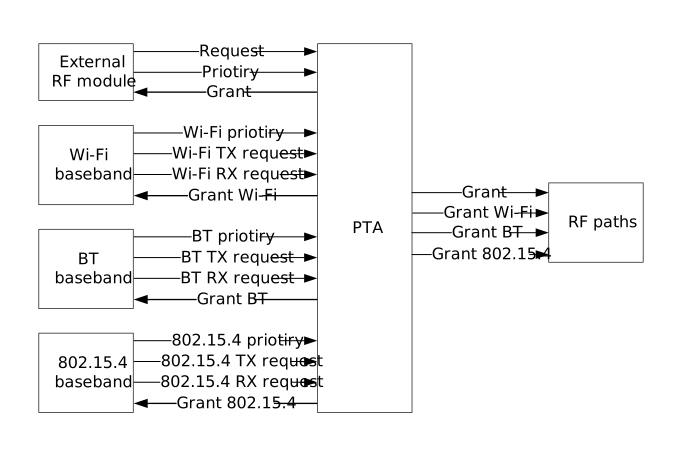
PTA circuit architecture diagram
Although PTA can arbitrate RF access grants on a per-packet basis, in high-traffic scenarios, frequent arbitration may cause more transmission interruptions, leading to more retransmissions and reduced communication efficiency. Continuously using the same configured priority arbitration logic will also lead to uneven resource allocation or uncontrollable outcomes. Therefore, some coexistence scenarios require TDMA to allocate time slots with different priority arbitration logic, to optimize coexistence performance.
TDMA
TDMA, based on PTA real-time arbitration, periodically allocates adjustable-length time slots to each module for continuous priority transmission, by configuring stronger PTA priority arbitration logic for each coexistence scenario, adapting to different scenarios and achieving optimal coexistence performance.
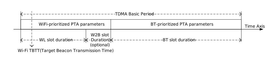
Wi-Fi and BT basic TDMA time-slice allocation diagram
Wi-Fi priority parameters and BT priority parameters favor their own priority transmissions, but still allow configuring high-priority transmissions from the other party to preempt their own time slots, achieving full flexibility.
The PTA and TDMA parameters for all supported coexistence scenarios on Ameba have been thoroughly tuned and validated to near-optimal states. No manual configuration of coexistence parameters by customers is required.
External RF Module Coexistence
PTA External Interface
As shown in the PTA block diagram, the external RF module can act as a PTA device and send transmission requests to the Ameba PTA host through the 3-wire interface, participating in the transmission grant arbitration of internal RF modules. The signal definitions and timing requirements of the 3-wire interface are as follows:
REQUEST: High level indicates the PTA device is requesting a transmission grant; low level indicates no transmission is being requested.
PRIORITY: After the rising edge of the REQUEST signal, the PTA host samples this signal at two time points. A high level at the end of the T1 sampling window indicates a high-priority transmission request; low level indicates a low-priority request. A high level at the end of the T2 sampling window indicates a transmit operation; low level indicates a receive operation.
GRANT: Represents the transmission grant output from the PTA host to the PTA device, indicating whether the device should continue or pause transmission. The corresponding active level must be configured according to the external circuit logic.
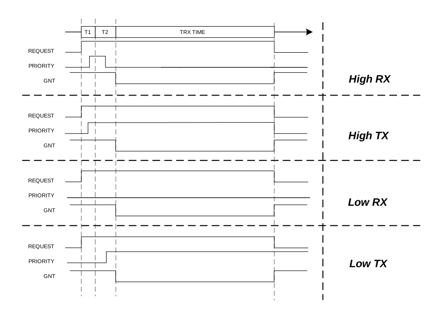
External RF module 3-wire PTA interface timing diagram
The external RF module and Ameba can each use independent antennas; alternatively, the GRANT signal can work together with antenna switching control signals to operate components such as a single-pole double-throw (SPDT) switch for shared antenna use.
External RF Module Coexistence Configuration
Refer to Project Configuration and use ameba.py menuconfig to open the project configuration, navigate to the CONFIG_COEX sub-configuration page, and configure DualChip-Coex development settings.
(Top) → CONFIG COEX

[*] Enable Coex
[*]     Enable Ext Coex Support
            PTA Mode (PTA Mode Simple)  --->
            Ext Protocol (Ext WPAN)  --->
            Priority Mode (Directional)  --->
            Request Polar (Request Active High)  --->
            Gnt Polar (Gnt Active Low)  --->
(2)         Priority Det Time (NEW)
(8)         TRX Det Time (NEW)
(PA_21)     Pin PTA Request (NEW)
(PA_18)     Pin PTA Priority (NEW)
(PA_19)     Pin PTA Gnt (NEW)
The configuration options are described below.
Enable Ext Coex Support
Enable: Enable when an external Bluetooth or 802.15.4 device needs to coexist with Ameba.
PTA Mode
PTA Mode Simple: Select when the external device uses the 802.15.4 protocol, or when it uses BT and Ameba’s internal BT is in use at the same time.
PTA Mode Advance: Select when the external device uses BT and Ameba’s internal BT is not in use.
Ext Protocol
Ext WPAN: Select when the external device uses 802.15.4.
Ext BT: Select when the external device uses BT.
Ext BT&WPAN: Select when the external device includes both BT and 802.15.4 that need to coexist.
Priority Mode
This option is configurable only when PTA Mode is set to “PTA Mode Simple”.
Directional: Select when the external PRIORITY signal supports identifying TX/RX direction.
Static: Select when the external PRIORITY signal only distinguishes high/low priority.
Request Polar
This option is configurable only when PTA Mode is set to “PTA Mode Simple”.
Request Active High: Select when the REQUEST signal is active-high (asserted high when requesting transmission).
Request Active Low: Select when the REQUEST signal is active-low (asserted low when requesting transmission).
Gnt Polar
This option is configurable only when PTA Mode is set to “PTA Mode Simple”.
Gnt Active Low: Select when the GNT signal is active-low (asserted low when granting transmission).
Gnt Active High: Select when the GNT signal is active-high (asserted high when granting transmission).
Priority Det Time / TRX Det Time
Priority Det Time corresponds to T1, and TRX Det Time corresponds to T2. Enter the values according to the external device specification.
Pinmux Setting
Ameba acts as the PTA Host and needs to configure the corresponding GPIO pins for the PTA 3-wire interface signals.
Pin PTA Request: Configure the GPIO pin to receive the external REQUEST signal.
Pin PTA Priority: Configure the GPIO pin to receive the external PRIORITY signal.
Pin PTA Gnt: Configure the GPIO pin to output the GRANT signal to the external device.
Enter the actual connected pin names according to the hardware schematic.

