Overview
Supported ICs[ RTL8721F ]
Introduction
The Controller Area Network (CAN) is a serial communication controller designed for high-reliability automotive and industrial applications. This module implements the CAN 2.0A/CAN 2.0B data link layer protocol defined in the ISO 11898-1 standard (excluding CAN FD), supporting multi-master communication, non-destructive arbitration, and robust error detection mechanisms.
Features
Fully compliant with CAN 2.0A and CAN 2.0B (ISO 11898-1), supporting 11-bit standard frames and 29-bit extended frames.
Provides 16 independent message buffers with individually configurable payload size and direction. The top 4 buffers can be flexibly configured in FIFO mode.
Supports hardware timestamping for precise capture of message transmission and reception times.
Supports flexible message transmission and reception mechanisms, including event- or time-triggered transmission, and hardware auto-reply for remote frames.
Supports configurable automatic retransmission upon transmission failure or arbitration loss.
Supports receive DMA transfers with a configurable DMA interface to improve data throughput and further reduce CPU load.
Supports triple sampling mode at low bit rates to effectively filter bus glitches, enhancing noise immunity and communication robustness.
Features comprehensive error confinement and detection mechanisms, provides multiple error interrupt outputs, and supports error counter warning thresholds (default warning threshold: 96).
Supports low-power wakeup with digital filtering, enabling system wakeup via specific bus activity in sleep mode.
Provides loopback and silent modes for node self-testing, bus monitoring, and offline debugging.
Block Diagram
The following figure illustrates the internal architecture of the CAN controller, including the Protocol Core, Message Processor, Message Buffers, Wakeup Circuit, and Register Interface.
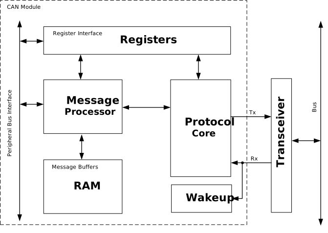
CAN Controller Block Diagram
Protocol Core: Executes the complete CAN underlying protocol logic, including bit timing control, frame parsing and assembly, clock division, and sampling mechanisms. The Protocol Core interacts with the Message Processor via a dedicated data and control interface to perform actual message transmission and reception.
Message Processor: Manages message scheduling and storage. It arbitrates RAM access between the APB bus and the Protocol Core to ensure data consistency. In the receive direction, it scans RAM to allocate storage space for incoming messages. In the transmit direction, it determines the next message to be transmitted based on priority. Additionally, the Message Processor supports hardware auto-reply or storage for remote frames.
Message Buffers: Dedicated internal SRAM space, managed by the Message Processor, used to buffer and store messages pending transmission and already received. Each CAN module contains 16 independently configurable message buffers.
Wakeup Circuit: Handles bus wakeup functionality. In low-power mode, it continuously monitors the Rx pin. Once a dominant (low) level is detected for a duration exceeding the predefined threshold, it triggers a wakeup signal to restore the CAN module and the entire system to the active state.
Register Interface: Allows the CPU to access the internal control and status registers of the CAN module for configuration, status querying, and interrupt management.
Transceiver: Typically located external to the controller, it converts the logic levels output by the Protocol Core into differential signals required by the physical bus, and converts bus differential signals back into logic levels for the controller to read.