Overview
The advanced control timer consists of a 16-bit auto-reload counter driven by a programmable prescaler. It is suitable for various applications, including measuring the pulse length of input signals (input capture) or generating output waveforms (output compare and PWM). Pulse length and waveform period can be adjusted between 25ns and 107s. Each timer is fully independent and does not share any resources with each other; different channels of the same timer share the same counter.
Capture Timer
Introduction
The capture timer is driven by a 16-bit auto-reload counter and a 16-bit programmable prescaler. It can be used for various purposes, including measuring the pulse length or count of input signals.
Features
The features of the capture timer are listed below.
Clock source is XTAL40MHz
Resolution is 16-bit
Quantity: 1
Prescaler bit width is 16-bit
Counter counting mode is up-counting
Supports pulse width measurement
Supports pulse count measurement
Supports interrupts
Block Diagram
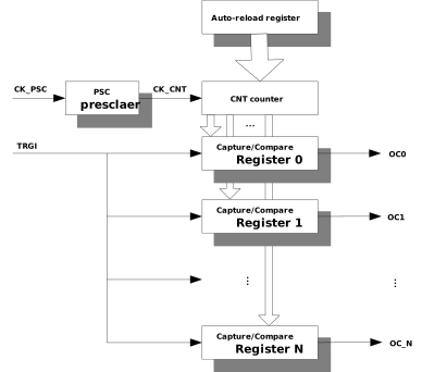
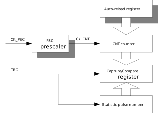
The capture timer is mainly composed of a counter, a preload register, a prescaler, and capture registers. The block diagram is shown below.
PWM Timer
Introduction
The PWM timer is driven by a 16-bit auto-reload counter and a 16-bit programmable prescaler. It can be used for various purposes, including measuring the pulse frequency of input signals (input capture), single pulse mode, and output waveform generation (PWM).
Features
Clock source: XTAL40M
Resolution: 16-bit
Prescaler: 16-bit
Count mode: Up-counting
Supports one-pulse mode
Supports PWM mode with polarity selection
Interrupt generation
Sleep mode
Duty cycle range: 0 to 100%
Supports phase shift function
Quantity:
{{IC_PARAM_PWMTIMER_QUANTITY}}Number of Channels:
{{IC_PARAM_PWMTIMER_CHANNEL_NUM}}
Quantity:
{{IC_PARAM_PWMTIMER_QUANTITY}}Number of Channels:
{{IC_PARAM_PWMTIMER_CHANNEL_NUM}}
Quantity:
{{IC_PARAM_PWMTIMER_QUANTITY}}Number of Channels:
{{IC_PARAM_PWMTIMER_CHANNEL_NUM}}
Quantity:
{{IC_PARAM_PWMTIMER_QUANTITY}}Number of Channels:
{{IC_PARAM_PWMTIMER_CHANNEL_NUM}}
Quantity:
{{IC_PARAM_PWMTIMER_QUANTITY}}Number of Channels:
{{IC_PARAM_PWMTIMER_CHANNEL_NUM}}
Quantity:
{{IC_PARAM_PWMTIMER_QUANTITY}}Number of Channels:
{{IC_PARAM_PWMTIMER_CHANNEL_NUM}}
Quantity:
{{IC_PARAM_PWMTIMER_QUANTITY}}Number of Channels:
{{IC_PARAM_PWMTIMER_CHANNEL_NUM}}
Quantity:
{{IC_PARAM_PWMTIMER_QUANTITY}}Number of Channels:
{{IC_PARAM_PWMTIMER_CHANNEL_NUM}}
Block Diagram
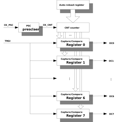
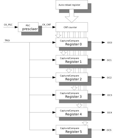
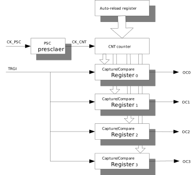
The PWM timer is mainly composed of a counter, a preload register, a prescaler, and capture/compare registers. Different channels of the same PWM timer share the same counter, and different channels can output waveforms with different duty cycles and phases. The block diagram is shown below.