Functional Description
Capture Timer
Up-Counting Mode
The timer is a 16-bit counter with an associated auto-reload register. Both the counter and the auto-reload register can be read and written by software. Read and write operations can be performed even when the counter is running.
The time base unit includes:
Counter register ( TIMx_CNT )
Auto-reload register ( TIMx_ARR )
Prescaler register ( TIMx_PSC )
The timer operates in upcounting mode, where the counter counts from 0 to the auto-reload value (the content of the TIMx_ARR register). When the counter reaches the auto-reload value, a counter overflow event occurs.
Pulse Width Measurement
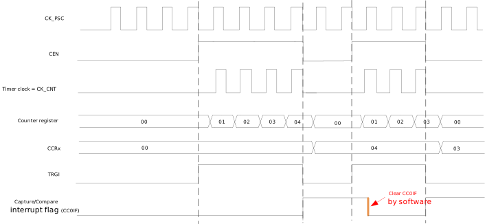
When the CC0PM bit of the TIMx_CCR0 register is set to 0, the capture timer operates in capture mode 0. In this mode, the width of the TRGI active level can be measured. When TRGI transitions from inactive level to active level, the counter is automatically enabled. When TRGI transitions from active level to inactive level, the counter is automatically disabled, CC0IF is set, and the current count value is copied to the CCR0 field of the TIMx_CCR0 register.
The figure below shows an example of the pulse width measurement mode, where the prescaler division factor is 1 and the rising edge of TRGI is used for capture.
Pulse Count Measurement
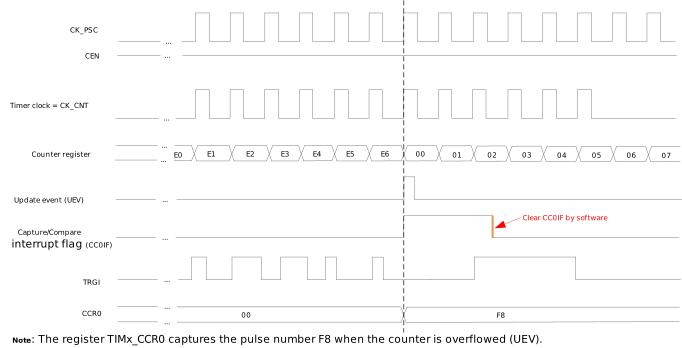
When the CC0PM bit of the TIMx_CCR0 register is set to 1, the capture timer operates in capture mode 1. In this mode, the number of valid edges of TRGI within a given period can be counted. When the counter overflows, CC0IF is set, and the count is copied to the CCR0 field of the TIMx_CCR0 register.
The diagram below shows an example of the pulse counting mode, where the prescaler divides by 1, the rising edge of TRGI is used for capture, and the ARR field is equal to E6.
Interrupt Events
There are two types of interrupt events for the capture timer:
Interrupt events in up-counting mode can be enabled by configuring the UIE bit of the TIMx_DIER register. When the UIE bit is 1, if an interrupt event occurs, it triggers a system interrupt. Both hardware overflow and software-triggered updates generate interrupts. The corresponding interrupt status can be checked through UIF in TIMx_SR , and the corresponding interrupt can be cleared by writing to UIF.
Interrupt events in capture mode can be enabled by configuring the CC0IE bit of the TIMx_DIER register. Capture mode 0: When TRGI transitions from active level to inactive level, an interrupt event is triggered, and the current count value is copied to the CCR0 field of the TIMx_CCR0 register ; Capture mode 1: When the counter overflows, an interrupt event is triggered, and the value of the counted pulse number is copied to the CCR0 field of the TIMx_CCR0 register.
PWM Timer
Upcounting Mode
The Timer is a 16-bit counter with an associated auto-reload register. Both the counter and the auto-reload register can be read and written by software. Read and write operations can be performed even while the counter is running.
The time base unit includes:
Counter register ( TIMx_CNT )
Auto-reload register ( TIMx_ARR )
Prescaler register ( TIMx_PSC )
The Timer operates in up-counting mode, where the counter counts from 0 to the auto-reload value (the content of the TIMx_ARR register). When the counter reaches the auto-reload value, a counter overflow event is generated.
Input Capture Mode
Input capture mode allows the timer to automatically latch the current counter value when a specific edge of an external trigger signal arrives. This function can be applied to application scenarios such as pulse width measurement, frequency calculation, and signal period detection.
The input capture mode is enabled by writing 1 to the CCxM bits in the TIMx_CCRx register. Once enabled, the CCRx field of the capture/compare register TIMx_CCRx will be used as a capture register to latch the counter value, and each channel has its own capture register.
When a valid transition edge of the TRGI signal is detected, the timer automatically latches the current counter value into the TIMx_CCRx register. Different channels can be configured with different polarities to capture different edges of the TRGI signal. At the same time, the CCxIF flag bit of the corresponding channel is set in the TIMx_SR status register. If the corresponding interrupt is enabled, the system will generate an interrupt request.
Software can clear this interrupt flag bit by writing 1 to the CCxIF bit.
One Pulse Mode
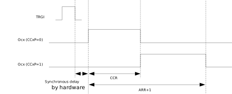
One-Pulse Mode (OPM) is a special case of PWM mode. It allows the counter to start in response to a stimulus and generate a pulse of programmable length after a programmable delay.
Starting the counter can be controlled by an active edge on TRGI, which can be a rising edge, falling edge, or both edges. The default output level in the idle state can be configured as high or low. The generated waveform can be completed in PWM mode. You can select One-Pulse Mode by setting the OPM bit in the TIMx_CR register. This will cause the counter to stop automatically at the next update.
The timing of One-Pulse Mode is shown in the following diagram.
Note
Since the channels are independent of each other, when TRGI is used to trigger one or more channels to output PWM signals, it can also be used as a capture source in the input capture mode of other channels.
PWM Mode
Pulse Width Modulation mode allows you to generate a signal whose frequency is determined by the value of the register and whose duty cycle is determined by the value of the CCRx field in the TIMx_CCRx register.
Period: TPWM = (ARR + 1) × TCNT
Duty cycle: DPWM = (CCRx × TCNT) / TPWM
Where: TCNT = TXTAL × (PSC + 1)
PWM mode can be selected independently on each channel (each OCx outputs a PWM) by setting the OCxM bits in the TIMx_CCRx register to 0. You must enable the corresponding preload register by setting the OCxPE bit in the TIMx_CCRx register, and finally enable the auto-reload preload register by setting the ARPE bit in the TIMx_CR register.
Since the preload register is only transferred to the shadow register when an update event occurs, you must initialize all registers by setting the UG bit in the TIMx_EGR register before starting the counter.
The OCx polarity can be programmed in software by the CCxP bit in the TIMx_CCRx register. It can be programmed as active high or active low.
In PWM mode, TIMx_CNT and CCRx (in TIMx_CCRx) are always compared to determine if TIMx_CNT < CCRx. As long as TIMx_CNT < CCRx, the PWM signal OCx remains active, otherwise it becomes inactive. If the comparison value in TIMx_CCRx is greater than the auto-reload value in TIMx_ARR, the PWM signal OCx output is active throughout the entire period. If the comparison value is 0, the PWM signal OCx output is inactive throughout the entire period.
This timer can only generate PWM in edge-aligned mode. The following diagram shows some examples of edge-aligned PWM waveforms, where TIMx_ARR = 8.
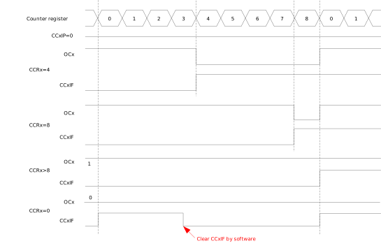
Edge-aligned PWM waveforms (ARR = 8, CCxP = 0)
Phase Synchronization Function
This function is used for users to configure specific phase shifts between channels. It only applies to PWM mode and One-Pulse mode, and input capture mode is not affected.
Note
The number of PWM channels varies by chip (see the Features section). This section uses 6 channels (channels 0 to 5) as an example.
Apart from the CNT in the TIMx_CNT register, the PWM timer provides one channel Counter for each channel. The value of a channel Counter can be obtained by reading its TIMx_PHASECNTx register (where x is the channel index). The value of each channel Counter is calculated based on the CNT value in the TIMx_CNT register. When the Counter value in TIMx_CNT changes, the channel values are updated immediately. Each channel’s waveform uses its own channel Counter as the reference.
The phase shift between channels is achieved by setting the phase shift of the channel Counter relative to the CNT value in the TIMx_CNT register. The phase shift function can be configured through the TIMx_PSYNCx register (where x is the channel index). When the phase shift function is enabled by setting the SYNCENx bit in the TIMx_PSYNCx register, the user can configure the phase shift between that channel’s Counter and the CNT value in TIMx_CNT, and the phase shift value is set by SYNCDIR and SYNCPHASE in TIMx_PSYNCx. When the phase shift function is disabled, that channel’s channel Counter value is exactly the same as CNT. The channel Counter value is:
channel Counter value = CNT - (-1)SYNCDIR* (SYNCPHASE)
The hardware always ensures that the channel values are in the 0-ARR range. When the channel Counter value is higher than ARR, it immediately becomes old value - ARR to stay in the 0-ARR range; when the channel Counter value is lower than zero, it immediately becomes old value + ARR.
Phase shift function shows the curve of the channel Counter value relative to the Counter, and the corresponding waveforms generated from the channel Counters of channels 0, 1, and 2. In the following configuration, the phase shift between every two channels is 1/3.
In the above example, for channel 0, the SYNCEN0 of channel 0 is 0, so channel counter0 is always equal to CNT. When channel counter0 is lower than CCR0 (i.e., 30), channel 0 outputs high level; when channel counter0 is higher than CCR0, channel 0 outputs low level. For channel 1, SYNCEN1 is set to 1, so channel counter1 has a phase shift with TIMx_CNT. The value of channel Counter 1 is CNT + 66, where CNT is the value of TIMx_CNT. When channel counter1 is lower than CCR1, channel 1 outputs high level, and vice versa. For channel 2, channel counter2 is CNT + 33. Under the above settings, there is a 1/3 phase shift between every two channels.
The software ensures that SYNCPHASEx is always less than the ARR value. Otherwise, a low level will be generated and output.
After the PWM timer is enabled and generates waveforms, users may need to update some parameters, such as period, duty cycle, and phase shift values. Since the ARR, PSC, CCRx, and PSYNCx registers can be configured as preloaded or non-preloaded, users have three ways to change the configuration at runtime.
Set the register as non-preloaded, then set the new value, and the new value will take effect immediately after the register value changes.
Set the register as preloaded, then set the new value, and the new value will be updated after the next UEV of CNT.
Set the register as preloaded, set the new value, and then write the UG bit, after which CNT will be cleared and start counting from 0, and the new value will take effect immediately. This is useful when multiple parameters need to be updated immediately.

Phase shift function
The following subsections explain some scenarios.
Immediate update
Change the period
Increase ARR value
waveform when ARR changes from 100 to 150 illustrates when ARR value is changed from 100 to 150. Because ARR is increased, the waveforms in the red cycle show that all three channels are in low-level state.
Decrease ARR value
waveform when ARR changes from 100 to 80 shows when ARR value is changed from 100 to 80. Before ARR is decreased, there is only one channel in high-level state at the same time. After ARR is set to 80, the waveforms in the red cycle show that channels 0 and 2 are both in high-level state in this case.
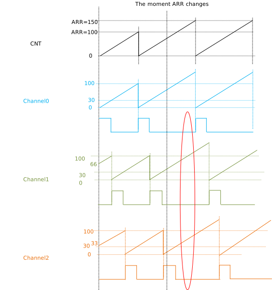
waveform when ARR changes from 100 to 150
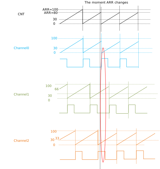
waveform when ARR changes from 100 to 80
Change the duty cycle
The duty cycle of each channel depends on its CCRx value which is configured individually in its own TIMx_CCRx registers. They can’t be updated exactly at the same time due to the time gap that CPU executes instructions. The length of this time gap is unpredictable. The following examples ignore this time gap.
Increase CCRx value
The following figure displays when CCRx changes from 30 to 40. For channel 2, CCR2 is changed when channel counter2 value is 35 and also
30 < 35 < 40, so that waveform of channel 2 falls into high level simultaneously when CCRx is updated. This causes a glitch. Also, channels 0 and 1 are both in high-level state because of increasing their CCRx in this case.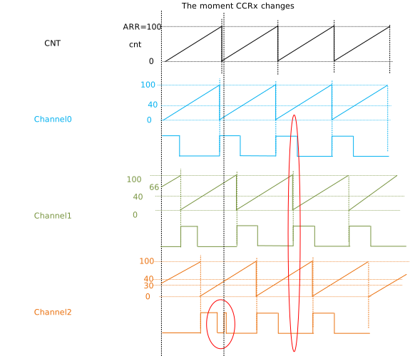
Decrease CCRx value
The following figure shows when CCRx changes from 30 to 20. For channel 2, CCR2 is changed when channel counter2 value is 25 and also
20 < 25 < 30, so that waveform of channel 2 falls into low level simultaneously when CCRx is updated. The duty cycle of channel 2 in this period is neither 20% nor 30%, but 25% instead.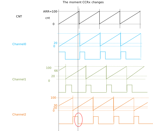
Change phase shift value
Phase shift of each channel is configured individually in TIMx_PSYNCx registers. They can’t be updated exactly at the same time and the following example ignore this time gap. Also, the change of phase shift always results in discrete channel counters and waveforms. The following figure is an example that phase shift of channel 1 changes from 66 to 36 and channel 2 from 33 to 63. For channel 1, channel counter1 is above and below CCR1 before and after changing. For channel 2, channel counter2 is below and above CCR2 before and after changing.
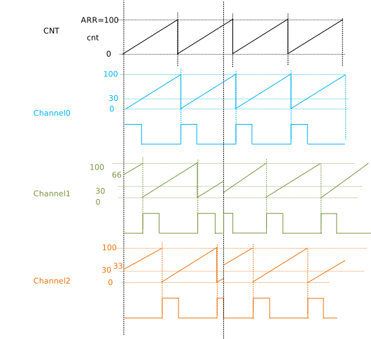
Waveforms when phase shifts change
Update after the next UEV of CNT
Change the period
Increase ARR value
Waveform when ARR changes from 100 to 150 illustrates when ARR value is changed from 100 to 150. Because ARR is increased, the waveforms in the red cycle show that all three channels are in low-level state in this case.
Decrease ARR value
Waveform when ARR changes from 100 to 80 shows when ARR value is changed from 100 to 80. Before ARR is decreased, there is only one channel in high-level state at the same time. After ARR is set to 80, the waveforms in the red cycle show that channels 0 and 2 are both in high-level state in this case.
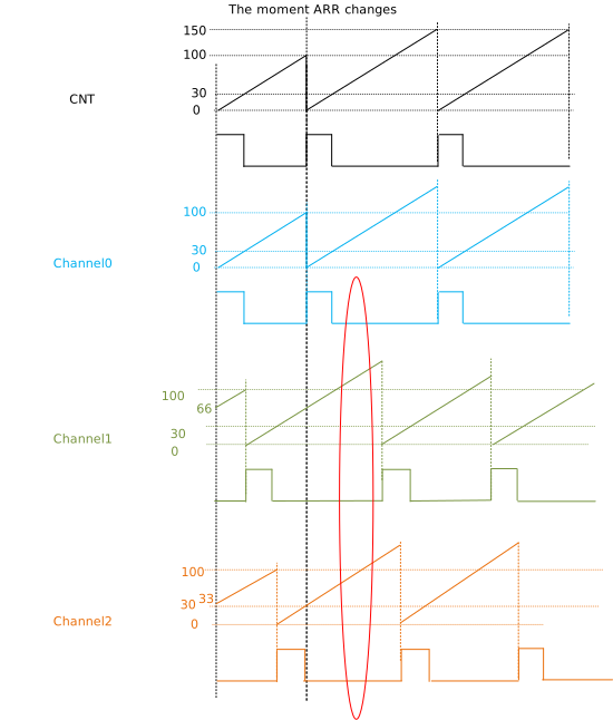
Waveform when ARR changes from 100 to 150
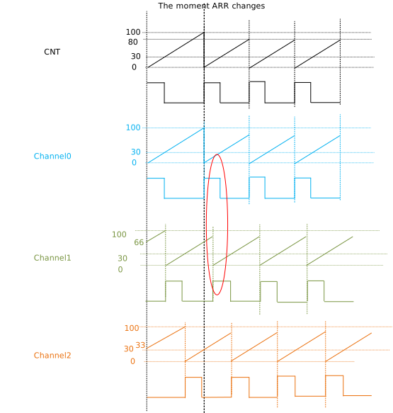
Waveform when ARR changes from 100 to 80
Change the duty cycle
The following examples ignore the time gap of configuration. The waveform is similar with cases that CCRx updates immediately.
Increase CCRx value
The following figure displays when CCRx changes from 30 to 40.
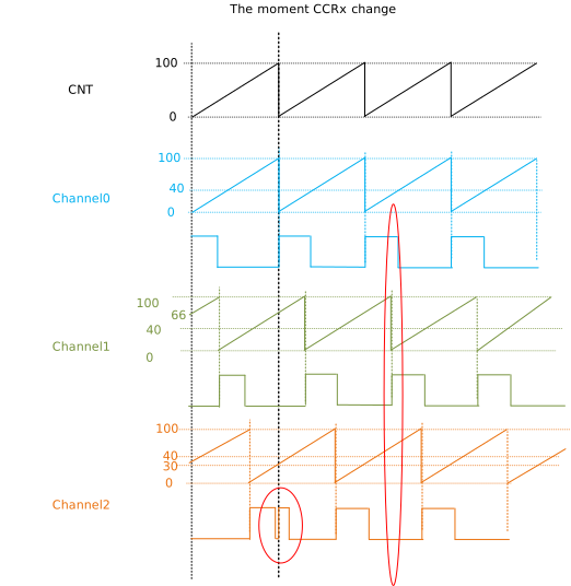
Decrease CCRx value
The following figure shows when CCRx changes from 30 to 20.
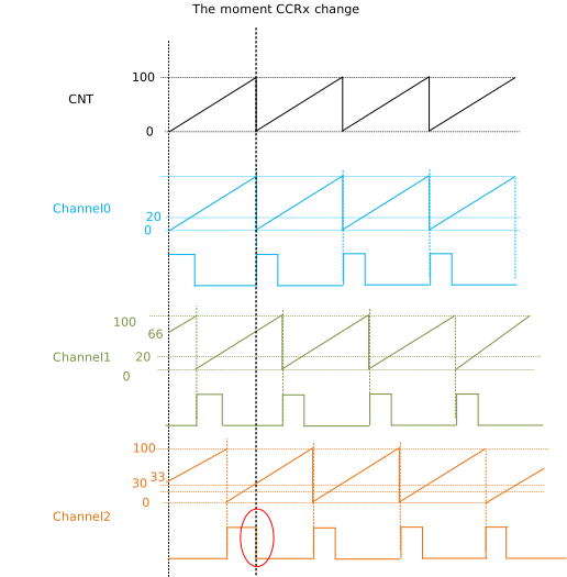
Change phase shift value
The following example ignores the time gap of configuration; the waveform is similar with cases that phase shifts update immediately.
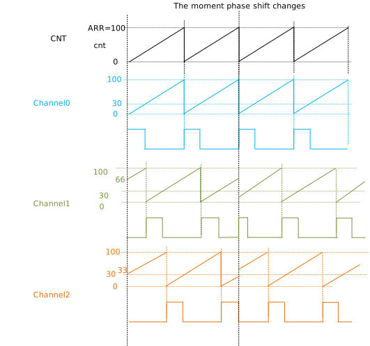
waveform when phase shift change
Update after writing the UG bit
Before writing the UG bit, the waveform was generated according to the old configuration. The new configuration comes into effect after writing the UG bit, and also CNT and channel counter are cleared to 0. In the following example, ARR changes from 100 to 150, CCRx not changed, phase shift function of channel 0 is disabled, phase shift of channel 1 changes from 66 to 33, and phase shift of channel 2 changes from 33 to 66.
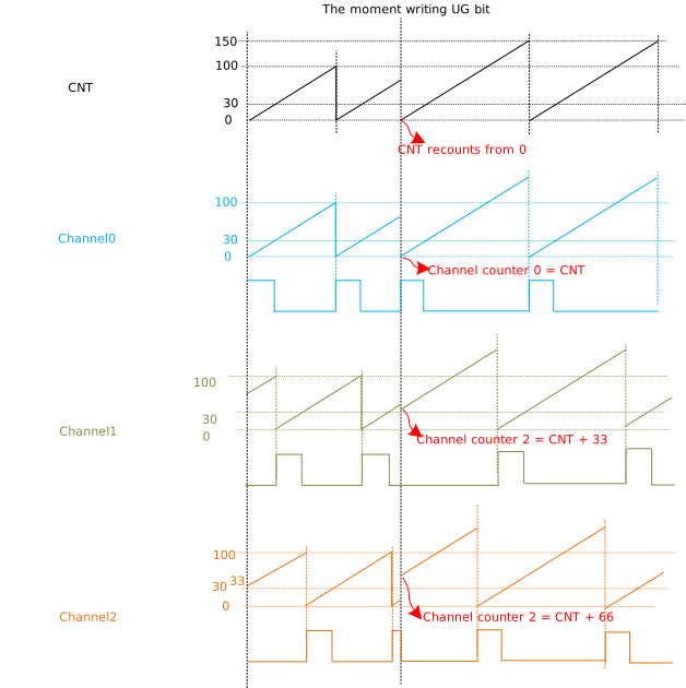
Waveform when writing UG bit