Transparent Communication Host Solution
Overview
The Abstract Control Model (ACM) under the USB Communication Device Class (CDC) is based on the USB Bulk Transfer mechanism and defines a set of universal data interaction standards. In Host mode, the system utilizes this protocol to establish a high-speed data channel with external devices, enabling bidirectional transparent transmission of raw data streams.
The Ameba platform integrates a USB-IF compliant CDC ACM protocol stack, capable of efficient data transparent transmission capabilities.

Features
Supports hot plugging
Automatically parse descriptors and adapt to speed modes
Batch transmission length and other parameters are configurable
Support transparent transmission of raw data (text, binary, custom protocols, etc.)
Support for independently identifying and driving the serial port functionality within composite devices (such as ACM + HID)
Application Scenarios
As a USB CDC ACM host, Ameba can establish a point-to-point communication link with devices through the USB interface, and combine its wireless capability to expand various data transparent transmission applications, such as:
Wireless Data Transparent Transfer Bridge: Ameba, as a gateway, can be mounted with an external proprietary protocol dongle or acquisition module to transparently forward the raw data stream received on the USB side to a Wi-Fi or Bluetooth network, achieving seamless bridging and protocol conversion of wired data streams to wireless networks.
Empowering Traditional Industrial Equipment: Ameba connects to PLCs, CNC machines, or precision instruments via a USB-to-serial adapter, enabling protocol conversion and cloud access for traditional RS-232/485 devices. This facilitates the digital and intelligent upgrade of old production lines at a low cost.
High-speed data acquisition: Ameba connects to high-frequency sensors or acquisition cards equipped with USB interfaces, utilizing a bulk transfer mechanism to process large volumes of raw data in real-time. This breaks through the bandwidth bottleneck of traditional low-speed interfaces, ensuring data integrity and real-time performance in high-frequency sampling scenarios.
Protocol Introduction
CDC (Communication Device Class) is a standard for general communication devices defined by the USB specification. Within its PSTN (Public Switched Telephone Network) subclass, the most commonly used is ACM (Abstract Control Model). It defines a standardized set of commands for controlling communication parameters, such as:
Set baud rate (such as 9600, 115200)
Configure data bits, stop bits, and parity bits
Control DTR/RTS and other line status signals
It is through ACM that a USB CDC device can be recognized by the host as a standard “virtual serial port”.
Protocol Document
The USB-IF has officially released the CDC (Class Driver Control) basic protocol and PSTN (Public Switched Telephone Network) sub-class specifications. During the development process, please refer to the following core documents:
Specification type |
Document |
|---|---|
CDC 1.2 (Communication Device Class Basic Protocol) |
https://www.usb.org/sites/default/files/CDC1.2_WMC1.1_012011.zip |
PSTN 1.2 (PSTN Subclass) |
PSTN120.pdf, which is included in the aforementioned CDC 1.2 zip file. |
Protocol Framework
The CDC ACM architecture utilizes a dual-interface mechanism to separate control flow from data flow, and logically binds them into a single functional unit via the Union Functional Descriptor.
Communication Class Interface (CCI)
Responsible for device management control and signaling interaction.
Control transmission: Transmit specific requests through the default control endpoint.
The host primarily sends PSTN control commands, with core instructions including SetLineCoding for configuring baud rate/data bits, and SetControlLineState for controlling RTS/DTR handshake signals.
Interrupt transmission: Utilizing interrupt input endpoints to achieve asynchronous status notification from the device to the host.
A typical application is to report changes in hardware signal status such as DCD, DSR, or Ring in real-time through SERIAL_STATE.
Data Class Interface (DCI)
Responsible for carrying application-layer payload data streams. This interface is typically configured as a pair of bulk endpoints (Bulk IN/Bulk OUT), serving solely as a transparent data transmission channel without involving the parsing or processing of control commands.
Example of protocol interaction:

Descriptor Structure
In addition to adhering to standard USB descriptors (such as device descriptor, configuration descriptor, and endpoint descriptor), CDC ACM devices also define Class-Specific Functional Descriptors to specify the capabilities of the abstract control model.
CDC ACM Descriptor Topology
The following example illustrates the descriptor topology using a High Speed configuration.
Device Descriptor
└── Identifies basic device information (Class: 0x02 CDC, SubClass: 0x02 ACM)

Configuration Descriptor
├── Includes total length, power attributes (Self-powered), etc.
│
├── Communication Class Interface Descriptor (Interface 0)
│   ├── Standard Interface Descriptor (Class: 0x02, SubClass: 0x02, Protocol: 0x01 AT Commands)
│   │
│   ├── Class-Specific Functional Descriptors (Defines ACM capabilities)
│   │   ├── Header Functional Descriptor (Declares CDC Spec version)
│   │   ├── Call Management Functional Descriptor (Call handling capabilities)
│   │   ├── ACM Functional Descriptor (Line coding & state capabilities)
│   │   └── Union Functional Descriptor (Binds Interface 0 and Interface 1)
│   │
│   └── Standard Endpoint Descriptor (Interrupt IN)
│       └── Used for Serial State notifications
│
├── Data Class Interface Descriptor (Interface 1)
│   ├── Standard Interface Descriptor (Class: 0x0A Data, SubClass: 0x00, Protocol: 0x00)
│   │
│   ├── Standard Endpoint Descriptor (Bulk OUT)
│   │   └── Host -> Device Data Stream
│   │
│   └── Standard Endpoint Descriptor (Bulk IN)
│       └── Device -> Host Data Stream
│
├── Device Qualifier Descriptor
│   └── Device information for other speed modes
│
└── Other Speed Configuration Descriptor
    └── Configuration information for Full Speed mode
Functional Descriptor
In the communication interface, the CDC must include the following special “function descriptor” header:
Header Functional Descriptor: Indicates the CDC version.
Call Management Functional Descriptor: Indicates how the device handles call management.
Abstract Control Management Functional Descriptor: Indicates which commands (such as Set_Line_Coding) are supported.
Union Functional Descriptor: specifies which one is the Master interface and which one is the Slave interface.
Header Functional Descriptor
Header Functional Descriptor
├── bLength            : 1 byte   → Total descriptor length (Fixed = 5 bytes)
├── bDescriptorType    : 1 byte   → 0x24 (CS_INTERFACE: Class-Specific Interface)
├── bDescriptorSubtype : 1 byte   → 0x00 (HEADER)
└── bcdCDC             : 2 bytes  → USB Class Definitions for Communication Devices Specification Release Number
                                    • 0x0110 = Release 1.10 (Common for ACM)
Call Management Functional Descriptor
Call Management Functional Descriptor
├── bLength            : 1 byte   → Total descriptor length (Fixed = 5 bytes)
├── bDescriptorType    : 1 byte   → 0x24 (CS_INTERFACE)
├── bDescriptorSubtype : 1 byte   → 0x01 (CALL_MANAGEMENT)
├── bmCapabilities     : 1 byte   → The capabilities that this configuration supports:
│                                   • Bit 0 = 0: Device does not handle call management itself
│                                   • Bit 0 = 1: Device handles call management itself
│                                   • Bit 1 = 0: Call management commands does not sent over Data Class Interface
│                                   • Bit 1 = 1: Call management commands can be sent over Data Class Interface
│                                   • Bits 2-7: Reserved (Reset to zero)
└── bDataInterface     : 1 byte   → Interface number of Data Class interface optionally used for call management
                                    (Zero if no data interface is used)
ACM Functional Descriptor
Abstract Control Management (ACM) Functional Descriptor
├── bLength            : 1 byte   → Total descriptor length (Fixed = 4 bytes)
├── bDescriptorType    : 1 byte   → 0x24 (CS_INTERFACE)
├── bDescriptorSubtype : 1 byte   → 0x02 (ABSTRACT_CONTROL_MANAGEMENT)
└── bmCapabilities     : 1 byte   → The capabilities that this configuration supports:
                                    • Bit 0: Comm_Feature (Supports Set_Comm_Feature, Clear_Comm_Feature, Get_Comm_Feature)
                                    • Bit 1: Line_Coding (Supports Set_Line_Coding, Set_Control_Line_State, Get_Line_Coding, Serial_State)
                                    • Bit 2: Send_Break (Supports Send_Break)
                                    • Bit 3: Network_Connection (Supports Network_Connection)
                                    • Bits 4-7: Reserved (Reset to zero)
Union Functional Descriptor
Union Functional Descriptor
├── bLength            : 1 byte   → Total descriptor length (3 + Number of slave interfaces)
├── bDescriptorType    : 1 byte   → 0x24 (CS_INTERFACE)
├── bDescriptorSubtype : 1 byte   → 0x06 (UNION)
├── bMasterInterface   : 1 byte   → The interface number of the Communication or Data Class interface
│                                   (Designated as the controlling interface for the union)
└── bSlaveInterface0   : 1 byte   → Interface number of the first subordinate interface in the union
│    ⋮
└── bSlaveInterface(N) : 1 byte   → Interface number of the last subordinate interface in the union
Note
For specifications regarding the CDC ACM transfer protocol, please refer to USB CDC ACM Specification 。
Class-Specific Requests
Control requests for CDC ACM devices are categorized into Standard Requests and Class-Specific Requests.
This section primarily introduces the class-specific requests unique to CDC ACM and utilized for implementing core functionalities such as serial port parameter configuration and flow control signal management for virtual serial ports.
Request Name |
Requirement |
Description |
|---|---|---|
SEND_ENCAPSULATED_COMMAND |
Required |
The host sends an encapsulated command to the device. The data format must adhere to the control protocol supported by the device (e.g., AT command set). |
GET_ENCAPSULATED_RESPONSE |
Required |
The host retrieves response data for an encapsulated command from the device. The response format adheres to the protocol supported by the device. |
SET_COMM_FEATURE |
Optional |
Sets the status of a specific communication feature. The target feature is specified by a feature selector. |
GET_COMM_FEATURE |
Optional |
Queries the current setting status of a specific communication feature. |
CLEAR_COMM_FEATURE |
Optional |
Clears the setting of a specific communication feature, resetting it to the default state. |
SET_LINE_CODING |
Optional (+) |
The host configures line coding properties for async serial communication (e.g., baud rate, stop bits, parity, data bits). |
GET_LINE_CODING |
Optional (+) |
The host queries the currently configured line coding properties for asynchronous serial communication. |
SET_CONTROL_LINE_STATE |
Optional |
The host controls the state of RS-232/V.24 standard control signals (e.g., DTR and RTS signal levels). |
SEND_BREAK |
Optional |
The host requests the device to generate a “Break” signal of a specific duration on the transmission end, simulating an RS-232 style line break. |
Note
The above requests all belong to Communications Class specific requests.
For Analog Modem applications, although the specification lists requests marked with
(+)as optional, it is strongly recommended to implement these requests to ensure compatibility.
Class Driver
This section details the internal implementation of the CDC ACM host driver, including the driver architecture, support for class-specific requests, and the allocation scheme for transmission resources.
Driver Architecture
The CDC ACM host protocol stack adopts a layered architecture design, decoupling the USB transport layer from the upper-layer data stream. From top to bottom, the driver architecture is divided into the following layers:
Application Layer
Contains business logic and data processing callbacks.
Business Implementation: Calls interfaces and processes transmitted/received data based on actual scenarios (such as wireless bridges, data acquisition).
Data Buffering: The application layer directly acquires data packets uploaded from the lower layer by registering user callback functions.
CDC ACM Class Driver
Strictly adhering to the USB CDC ACM protocol specification, this layer implements the core business logic for the interaction between the host and the ACM device. Its main responsibilities include:
Enumeration and Interface Binding: Responsible for identifying the communication interface class (0x02, CDC_COMM) and data interface class (0x0A, CDC_DATA), automatically parsing interface descriptors, and applying for corresponding pipe resources.
Transmission Parameter Negotiation: During the initial connection phase, it is responsible for sending requests such as SetLineCoding to initialize link parameters, ensuring configuration synchronization between the host and device.
Notification Event Handling: Listens for status notifications reported by the device (such as SerialState) via interrupt transfers and triggers corresponding event callbacks.
Data Transmission: Encapsulates data streams from the upper layer into USB Bulk Transfer Requests (URB) and passes received USB data packets to the application layer via callback functions.
USB Core Driver
Responds to hardware interrupts in real-time, responsible for handling USB standard enumeration, transfer management, and underlying physical data transmission scheduling.
Class Driver Implementation
The CDC ACM class driver plays a connecting role in the system architecture. Its implementation logic mainly revolves around the following three core interaction interfaces:
Host Class Driver Callback API: The class driver interacts with the underlying USB Core by defining and registering a standard
usbh_class_driver_tstructure.Application-Facing Callback API: The class driver provides an asynchronous event notification mechanism to the upper-layer application via the
usbh_cdc_acm_cb_tcallback structure.Application-Facing API: After the application layer calls these APIs, the driver switches the internal state machine status and initiates data transmission scheduling.
Driver Callback Mechanism
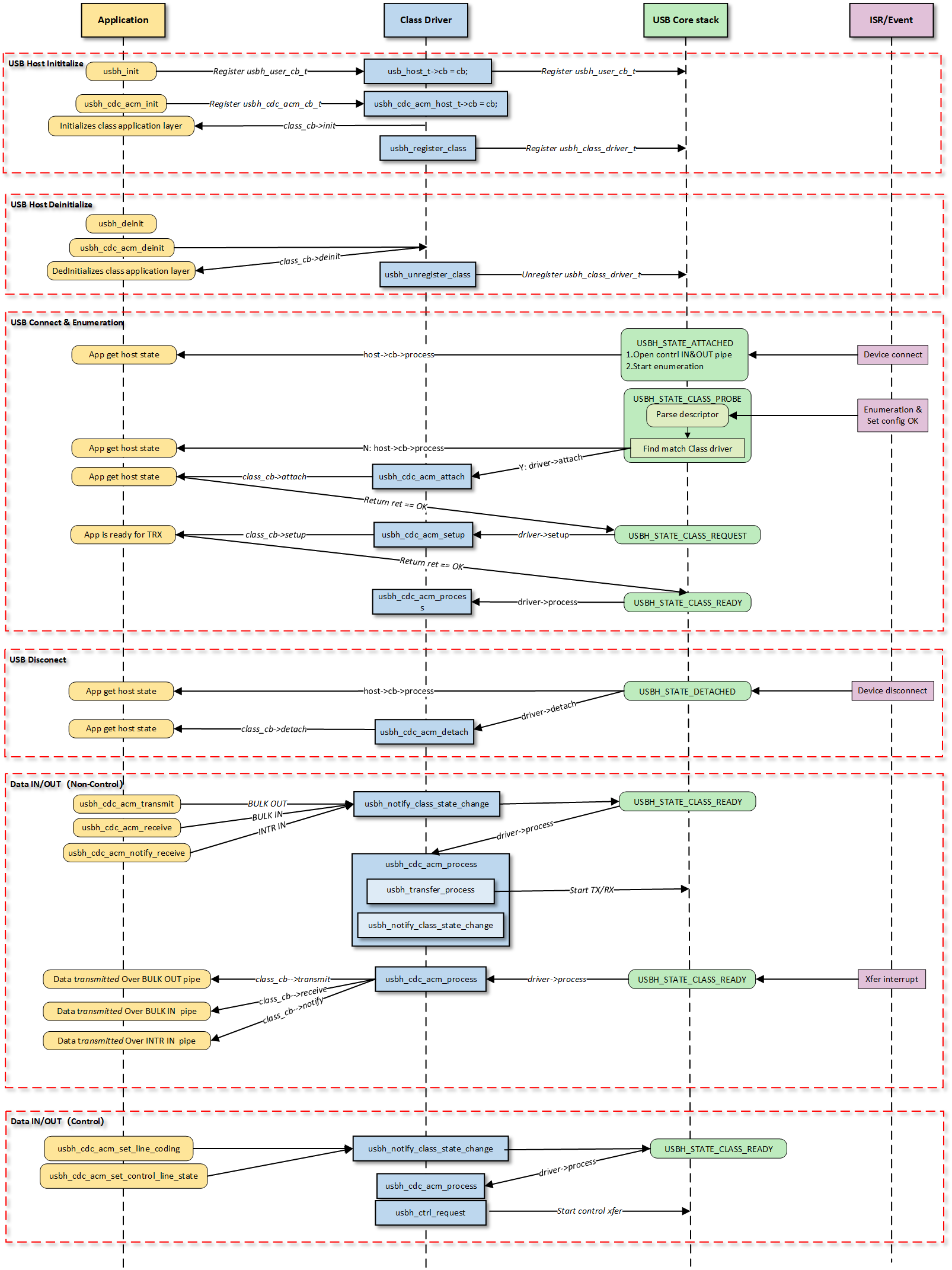
Note
The figure above illustrates the execution flow of callback functions at different levels and does not list all calling scenarios.
Class Driver Callback Functions
The class driver needs to define a standard usbh_class_driver_t structure.
This serves as a unified entry point registered with the USB Core and is the primary method for the Core layer to notify the Class layer that “an event has occurred.”
id_table: Supported device ID list. The core layer uses this table to match with the inserted device to determine whether to load this driver.
attach: Called after device connection and successful matching.
detach: Called when the device is disconnected.
setup: Called when enumeration is complete and the class request phase begins. Used to send class-specific standard control requests to complete necessary configuration before the device enters the data transfer state.
process: The state machine processing function executed after the class driver is ready.
sof: Called during SOF interrupts. Used to handle logic with strict timing requirements, primarily for isochronous transfers.
completed: Called when a transfer on a pipe completes.
Application Layer Callback Functions
The CDC ACM class driver application layer callback structure usbh_cdc_acm_cb_t is implemented by the user layer. Generally, the following APIs can be implemented:
API |
Description |
|---|---|
init |
Called during class driver initialization to initialize application-related resources. |
deinit |
Called during class driver de-initialization to release application-related resources. |
attach |
Called when the class driver executes the attach callback to handle device connection events at the application layer. |
detach |
Called when the class driver executes the detach callback to handle device disconnection events at the application layer. |
setup |
Called when the class driver executes the setup callback, indicating that the application layer class driver is ready for data transfer. |
receive |
Called when the class driver receives BULK IN data, used by the application layer to process data reported by the device. |
transmit |
Called when the class driver BULK OUT data transfer completes, used by the application layer to obtain the OUT transfer status. |
notify |
Called when the class driver receives INTR IN data, used by the application layer to process data reported by the device. |
Loading and Unloading Class Driver
These two functions are responsible for the allocation and release of memory resources, as well as the registration and deregistration of the class driver to the USB core.
usbh_cdc_acm_init() is the top-level function used to load the CDC ACM host class driver. It primarily completes the following tasks:
Saves the user-provided callback functions and calls the user
initcallback.Allocates memory for
line_coding(current device parameters) anduser_line_coding(user expected parameters).Calls
usbh_register_class()to register the CDC ACM class driver with the USB host core.
Example:
int usbh_cdc_acm_init(usbh_cdc_acm_cb_t *cb)
{
    /* 1. Save the user callback and call the user's ``init`` callback */
    if (cb != NULL) {
      cdc->cb = cb;
      if (cb->init != NULL) {
        ret = cb->init();
        if (ret != HAL_OK) {
          RTK_LOGS(TAG, RTK_LOG_ERROR, "User init err %d\n", ret);
          return ret;
        }
      }
    }
    /* 2. Allocate memory */
    cdc->line_coding = (usb_cdc_line_coding_t *)usb_os_malloc(sizeof(usb_cdc_line_coding_t));
    /* ... */

    /* 3. Register class driver*/
    usbh_register_class(&usbh_cdc_acm_driver);
    return ret;
}
usbh_cdc_acm_deinit() is the top-level function used to unload the CDC ACM host class driver, responsible for cleaning up resources:
Calls the user
deinitcallback to inform the application layer.If the device is in a connected state, forcibly closes all open pipes (Interrupt IN, Bulk IN, Bulk OUT).
Frees the previously allocated memory.
Deregisters the class driver.
Example:
int usbh_cdc_acm_deinit(void)
{

  /* 1. Call the user's ``deinit`` callback  */
  if ((cdc->cb != NULL) && (cdc->cb->deinit != NULL)) {
    cdc->cb->deinit();
  }

  /* 2. If the device is connected, forcefully close all open pipes */
  if ((host != NULL) && (host->connect_state == USBH_STATE_SETUP)) {
    usbh_close_pipe(host, &cdc->intr_in);
    /* Close other pipes */
  }

  /* 3. Free memory */
  if (cdc->line_coding != NULL) {
    usb_os_mfree(cdc->line_coding);
  }
  /* ... */

  /* 4. Unregister class driver*/
  usbh_unregister_class(&usbh_cdc_acm_driver);
  return ret;
}
Connection and Disconnection Handling
When the USB core detects the insertion or removal of a device matching the CDC ACM class, the following callback functions are called.
usbh_cdc_acm_attach is a key step in device enumeration, responsible for parsing interface descriptors and allocating pipe resources:
Locate Communication Interface (Comm Interface): If found, parses its interrupt endpoint and opens the Interrupt IN pipe.
Locate Data Interface (Data Interface): If found, parses its bulk endpoints and opens Bulk IN and Bulk OUT pipes.
Initialize the state machine to IDLE state.
Call the user
attachcallback to inform the application layer of the connection status.
Example:
static int usbh_cdc_acm_attach(usb_host_t *host)
{
  /* 1. Get the Communication interface and open the interrupt pipe */
  dev_id.bInterfaceClass = USB_CDC_COMM_INTERFACE_CLASS_CODE;
  itf_data = usbh_get_interface_descriptor(host, &dev_id);
  if (itf_data) {
    usbh_open_pipe(host, intr_in, ep_desc);
  }
  /* 2. Get the Data interface and open the Bulk IN & Bulk OUT pipe */
  dev_id.bInterfaceClass = USB_CDC_DATA_INTERFACE_CLASS_CODE;
  itf_data = usbh_get_interface_descriptor(host, &dev_id);
  /* Open bulk_in / bulk_out pipes */

  /* 3. Initialize the state machine */
  cdc->state = USBH_CDC_ACM_STATE_IDLE;

  /* 4. Notify the user layer */
  if ((cdc->cb != NULL) && (cdc->cb->attach != NULL)) {
      cdc->cb->attach();
  }
  return HAL_OK;
}
usbh_cdc_acm_detach is called when the device is removed. It is responsible for notifying the upper-layer application that the device has been removed and closing all relevant pipes to release hardware channels.
Example:
static int usbh_cdc_acm_detach(usb_host_t *host)
{
  /* 1. Notify the user layer */
  if ((cdc->cb != NULL) && (cdc->cb->detach != NULL)) {
    cdc->cb->detach();
  }
  /* 2. Close pipes */
  if (intr_in->pipe_num) {
    usbh_close_pipe(host, intr_in);
  }
  /* Close bulk_in / bulk_out pipes */
  return HAL_OK;
}
Class Driver State Machine
The usbh_cdc_acm_process callback function is the core state machine handler for the host-side CDC ACM class.
Unlike the passive response mechanism on the device side, the host-side driver must actively maintain the device state.
Its core responsibilities include maintaining the class driver lifecycle states (e.g., IDLE, TRANSFER, ERROR), handling the setting and verification of Line Coding, and distributing data transmission tasks.
State Machine Management and Scheduling
usbh_cdc_acm_process manages the scheduling of control transfers (such as baud rate configuration) and bulk/interrupt data transfers based on the current class driver state.
State Enum |
Description |
Key Actions |
|---|---|---|
IDLE |
Idle state |
Waits for user commands or data transmission requests. |
SET_LINE_CODING |
Send baud rate setting request |
Sends a |
GET_LINE_CODING |
Get/Verify baud rate |
Sends a |
SET_CONTROL_LINE_STATE |
Control handshake signals |
Configures RTS/DTR level states. |
TRANSFER |
Data transferring |
Distributes tasks to specific TX/RX processing functions based on the pipe number. |
ERROR |
Error state |
Attempts to clear endpoint features (Clear Feature) to restore communication. |
Line Coding Configuration (Set & Verify)
The CDC ACM host driver implements a “Set-Readback-Verify” closed-loop process to ensure the device has correctly accepted parameters like the baud rate.
Set: Sends the
SET_LINE_CODINGrequest. Upon success, the state automatically transitions toGET_LINE_CODING.Readback (Get): Sends the
GET_LINE_CODINGrequest to read the current configuration from the device, ensuring serial parameters are synchronized.Verify: Compares the configuration requested by the user with the actual configuration returned by the device. If they match, the configuration is successful. The
line_coding_changedcallback is called to notify the application layer of the successful modification.
Example:
case USBH_CDC_ACM_STATE_SET_LINE_CODING:
  /* 1. Send a setting request */
    req_status = usbh_cdc_acm_process_set_line_coding(host, cdc->user_line_coding);
  if (req_status == HAL_OK) {
    /* 2. After successful setup, immediately goto to get the setting for verification */
    cdc->state = USBH_CDC_ACM_STATE_GET_LINE_CODING;
    }
  /* ... error handling ... */
  break;

  case USBH_CDC_ACM_STATE_GET_LINE_CODING:
    req_status = usbh_cdc_acm_process_get_line_coding(host, cdc->line_coding);
    if (req_status == HAL_OK) {
      cdc->state = USBH_CDC_ACM_STATE_IDLE;
      /* 3. Verify whether the readback data is consistent with the user settings */
      if ((cdc->line_coding->b.dwDteRate == cdc->user_line_coding->b.dwDteRate) &&
      /* ... compare other fields ... */ ) {
        /* 4. Config Match, notify the application layer that the setting has been changed. */
        if ((cdc->cb != NULL) && (cdc->cb->line_coding_changed != NULL)) {
          cdc->cb->line_coding_changed(cdc->line_coding);
        }
    }
  }
  break;
Transfer Processing Distribution
When in the TRANSFER state, processing is distributed to specific TX (transmit), RX (receive), or INTR (interrupt) handler functions based on the pipe number (Pipe ID) that triggered the event.
Example:
case USBH_CDC_ACM_STATE_TRANSFER:
/* Distribute transmission tasks according to pipe numbers */
if (event.msg.pipe_num == cdc->bulk_out.pipe_num) {
  usbh_cdc_acm_process_tx(host);      // Handle BULK OUT transfer
} else if (event.msg.pipe_num == cdc->bulk_in.pipe_num) {
  usbh_cdc_acm_process_rx(host);      // Handle BULK IN transfer
} else if (event.msg.pipe_num == cdc->intr_in.pipe_num) {
  usbh_cdc_acm_process_intr_rx(host); // Handle Interrupt IN transfer(e.g. Serial State)
}
break;
Error Recovery
When an error occurs during other state processing, the driver attempts to clear endpoint features (Clear Feature) and restore to the IDLE state.
Example:
switch (cdc->state) {
/* ... IDLE state ... */

case USBH_CDC_ACM_STATE_ERROR:
  /* Error recovery mechanism */
  req_status = usbh_ctrl_clear_feature(host, 0x00U);
  if (req_status == HAL_OK) {
    cdc->state = USBH_CDC_ACM_STATE_IDLE;
  }
break;
}
Class-Specific Request Processing
Setup Phase Processing
The usbh_cdc_acm_setup callback function is invoked after the basic enumeration is completed.
It initiates the first class-specific request: Get Line Coding, to synchronize the state between the host and the device.
Example:
static int usbh_cdc_acm_setup(usb_host_t *host)
{
    /* Initiate a Get Line Coding request */
    status = usbh_cdc_acm_process_get_line_coding(host, cdc->line_coding);
    return status;
}
APIs for Application
Interfaces provided to the upper-layer application for triggering configuration or data transmission.
Set Control State
usbh_cdc_acm_set_control_line_state(): Switches the state to SET_CONTROL_LINE_STATE and schedules the initiation of the control request within process.
Set/Get Line Coding
usbh_cdc_acm_set_line_coding(): Assembles the Setup packet; the driver switches the state to SET_LINE_CODING and schedules the initiation of the control request within process.usbh_cdc_acm_get_line_coding(): Returns the device parameters read back for verification after the SET_LINE_CODING state.
Data Transfer Processing
The following three APIs for application serve as the interface layer between the USB driver and the application. The driver switches the state to TRANSFER and schedules the distribution of data transmission within the process callback.
CDC ACM Data Interface:
usbh_cdc_acm_transmit(): The application layer passes in data to initiate transmission. It handles Zero Length Packet (ZLP) logic and notifies the application layer of the transmission result via the user transmit callback function.usbh_cdc_acm_receive(): Initiates reception and passes data through to the application layer via the user receive callback function.
CDC ACM Communication Interface:
usbh_cdc_acm_notify_receive(): Initiates interrupt transfer reception and passes data through to the application layer via the user notify callback function.
Transmission Logic and Zero Length Packet (ZLP) Processing
In the bulk data transmission function usbh_cdc_acm_transmit(), the driver must handle the Zero Length Packet (ZLP) issue defined in the USB protocol.
If the length of the transmitted data is exactly an integer multiple of the endpoint’s Maximum Packet Size (MPS), the host must send an additional ZLP to inform the device that the transmission has ended. This is a standard requirement for USB bulk transfers.
Example:
int usbh_cdc_acm_transmit(u8 *buf, u32 len)
{
    usbh_cdc_acm_host_t *cdc = &usbh_cdc_acm_host;
    usb_host_t *host = cdc->host;
    usbh_pipe_t *pipe = &cdc->bulk_out;

    if (pipe->xfer_state == USBH_EP_XFER_IDLE) {
        pipe->xfer_buf = buf;
        pipe->xfer_len = len;

        /* If the data length is greater than 0 and an integer multiple of MPS, a ZLP needs to be sent */
        if ((pipe->xfer_len > 0) && (pipe->xfer_len % pipe->ep_mps) == 0) {
            pipe->trx_zlp = 1;
        } else {
            pipe->trx_zlp = 0;
        }

        cdc->state = USBH_CDC_ACM_STATE_TRANSFER;
        pipe->xfer_state = USBH_EP_XFER_START;
        /* ... notify state change ... */
    }
}
Class-Specific Request Implementation
This driver stack follows the USB CDC ACM specification, encapsulating the implementation and transmission process of core Class-Specific Requests.
Although the specification marks some requests as optional, the host driver implements the following requests to support standard virtual serial port applications.
Developers can refer to the source code path {SDK}/component/usb/host/cdc_acm for extensions.
Class-Specific Request |
Description |
|---|---|
SetLineCoding |
Configures line coding. Sends parameters such as baud rate, stop bits, and parity bits to the device. In pure passthrough mode, this request is mainly used to complete the protocol handshake process. |
GetLineCoding |
Gets line coding. Reads the current line configuration parameters from the device, used to verify if the configuration has taken effect or to synchronize with the device’s default state. |
SetControlLineState |
Sets control signal state. Used to control RTS (Request To Send) and DTR (Data Terminal Ready) signal levels, commonly used for flow control handshakes or to notify the device that the host side is ready. |
Pipe Configuration
The CDC ACM host driver parses the configuration descriptor during the device enumeration phase (usbh_cdc_acm_attach callback function), automatically finding and allocating corresponding transmission resources based on interface subclasses to establish complete data and control channels.
Count |
Description |
|---|---|
2 |
For default control transfer 0. Used for sending standard USB requests and CDC class-specific control requests (e.g., SetLineCoding). |
1 |
For Interrupt IN transfer. Belongs to the Communication Interface (CCI), used to receive notification events (Notify) actively reported by the device. The maximum timeout is set to 1000 ticks. |
1 |
For Bulk IN transfer. Belongs to the Data Interface (DCI), used to receive raw data streams (RX Data) uploaded by the device, supporting large packet transmission and ZLP processing. |
1 |
For Bulk OUT transfer. Belongs to the Data Interface (DCI), used to send raw data streams (TX Data) to the device. The driver layer optimizes DMA scheduling to ensure high-bandwidth transmission. |
API Reference
For detailed function prototypes and usage, please refer to the Driver API
Application Example
Application Design
This section details the complete development process for the CDC ACM Host driver, covering driver initialization, hot-plug management, data transmission and reception mechanisms, and resource release.
Driver Initialization
Before using the CDC ACM Host driver, it is necessary to define the configuration structure and register callback functions, followed by sequentially calling core interfaces to start the USB host controller and the ACM class driver.
Step Description:
Hardware Configuration: Set the USB speed mode (High Speed/Full Speed) and related interrupt priorities.
Callback Registration: Define the
usbh_cdc_acm_cb_tstructure and mount handler functions for each phase (connection, disconnection, data transmission, notification).Core Initialization: Call
usbh_init()to initialize the USB core stack.Class Driver Initialization: Call
usbh_cdc_acm_init()to initialize the CDC ACM class driver.
/* 1. Configure USB speed (High Speed or Full Speed), isr priority and main task priority. */
static usbh_config_t usbh_cfg = {
    .speed = USB_SPEED_HIGH,
    .ext_intr_enable = USBH_SOF_INTR,
    .isr_priority = INT_PRI_MIDDLE,
    //...
};

/* 2. Define USB user-level callbacks. */
static usbh_user_cb_t usbh_usr_cb = {
    .process = cdc_acm_cb_process    /* USB callback to handle class-independent events in the application */
};

/* 3. Define user callbacks for CDC ACM events. */
static usbh_cdc_acm_cb_t cdc_acm_usr_cb = {
    .init   = cdc_acm_cb_init,        /* Class init callback */
    .deinit = cdc_acm_cb_deinit,      /* Class deinit callback */
    .attach = cdc_acm_cb_attach,      /* Device attach callback */
    .detach = cdc_acm_cb_detach,      /* Device detach callback */
    .setup  = cdc_acm_cb_setup,       /* Class setup callback */
    .transmit = cdc_acm_cb_transmit,  /* Data transmit callback */
    .receive  = cdc_acm_cb_receive,   /* Data receive callback */
    .notify   = cdc_acm_cb_notify,    /* Interrupt notify callback */
};

int status = 0;

/*4. Initialize USB host core driver with configuration. */
status = usbh_init(&usbh_cfg, &usbh_usr_cb);
if (status != HAL_OK) {
   return;
}

/* 5. Initialize CDC ACM class driver.  */
status = usbh_cdc_acm_init(&cdc_acm_usr_cb);
if (status != HAL_OK) {
    /* If class driver init fails, clean up the core driver */
    usbh_deinit();
    return;
}
Hot-Plug Event Handling
Monitor the connection and disconnection of CDC ACM devices by registering the attach and detach callback functions in usbh_cdc_acm_cb_t.
In the example code, semaphore mechanisms are used to synchronize states:
Attach: When a device is inserted and enumerated successfully, the
attachcallback is triggered, releasing thecdc_acm_attach_semato notify the main thread to start data testing.Detach: When a device is removed, the
detachcallback is triggered, releasing thecdc_acm_detach_semato trigger the hot-plug management thread for resource cleanup and re-initialization.
/* 1. Configure USB status change callback */
static usbd_cdc_acm_cb_t cdc_acm_cb = {
    .status_changed = cdc_acm_cb_status_changed
};

/* 2. Configure Callback executed in ISR context */
static void cdc_acm_cb_status_changed(u8 old_status, u8 status)
{
    RTK_LOGS(TAG, RTK_LOG_INFO, "Status change: %d -> %d \n", old_status, status);

    cdc_acm_attach_status = status;
    rtos_sema_give(cdc_acm_attach_status_changed_sema);
}

/* 3. Create thread handling the state machine */
static void cdc_acm_hotplug_thread(void *param)
{
    int ret = 0;
    UNUSED(param);

    for (;;) {
        if (rtos_sema_take(cdc_acm_attach_status_changed_sema, RTOS_SEMA_MAX_COUNT) == RTK_SUCCESS) {
            if (cdc_acm_attach_status == USBD_ATTACH_STATUS_DETACHED) {
                RTK_LOGS(TAG, RTK_LOG_INFO, "DETACHED\n");

                /* 1.Clean up resources */
                usbd_cdc_acm_deinit();
                ret = usbd_deinit();
                if (ret != 0) {
                    break;
                }

                /* 2.Re-initialize for next connection */
                ret = usbd_init(&cdc_acm_cfg);
                if (ret != 0) {
                    break;
                }
                ret = usbd_cdc_acm_init(CONFIG_CDC_ACM_BULK_OUT_XFER_SIZE, CONFIG_CDC_ACM_BULK_IN_XFER_SIZE, &cdc_acm_cb);
                if (ret != 0) {
                    usbd_deinit();
                    break;
                }
            } else if (cdc_acm_attach_status == USBD_ATTACH_STATUS_ATTACHED) {
                RTK_LOGS(TAG, RTK_LOG_INFO, "ATTACHED\n");
            } else {
                RTK_LOGS(TAG, RTK_LOG_INFO, "INIT\n");
            }
        }
    }
    RTK_LOGS(TAG, RTK_LOG_INFO, "Hotplug thread fail\n");
    rtos_task_delete(NULL);
}
Data Transfer Processing
Once the CDC ACM device is successfully enumerated, the host can perform control transfers, data transfers, and interrupt notification reception.
Control Request
The host uses
usbh_cdc_acm_get_line_coding()andusbh_cdc_acm_set_line_coding()to get or set serial parameters such as baud rate and stop bits.Example: Set the baud rate to 38400 and perform readback verification.
static void cdc_acm_request_test(void)
{
    int ret;
    usbh_cdc_acm_line_coding_t line_coding;
    usbh_cdc_acm_line_coding_t new_line_coding;

    /* Wait for device attach */
    ......

    /* 1. Get current line coding from device */
    ret = usbh_cdc_acm_get_line_coding(&line_coding);
    if (ret != HAL_OK) {
        /* Get failed */
    }

    /* 2. Modify configuration parameters */
    /* Baudrate: 38400, Stop bits: 1, Parity: None, Data bits: 8*/
    line_coding.b.dwDteRate = 38400;
    line_coding.b.bCharFormat = CDC_ACM_LINE_CODING_CHAR_FORMAT_1_STOP_BITS;
    line_coding.b.bParityType = CDC_ACM_LINE_CODING_PARITY_NO;
    line_coding.b.bDataBits = 8;

    /* 3. Set new line coding to device */
    ret = usbh_cdc_acm_set_line_coding(&line_coding);
    if (ret != HAL_OK) {
        /* Set failed */
    }

    /* Wait for the setting to take effect */
    rtos_time_delay_ms(10);

    /* 4. Get line coding again to verify */
    ret = usbh_cdc_acm_get_line_coding(&new_line_coding);

    /* 5. Compare set values with read-back values */
    ......
}
Bulk Transfer
The driver uses an asynchronous transmission mechanism, combined with semaphores to implement synchronization logic:
Send: Call
usbh_cdc_acm_transmit()to send data. Upon completion, the driver calls back thetransmitfunction and releasescdc_acm_send_sema.Receive: Call
usbh_cdc_acm_receive()to prepare to receive data. Upon receiving data, the driver calls back thereceivefunction and releasescdc_acm_receive_sema.
/* RX Callback: Handle Reception Completion */
static int cdc_acm_cb_receive(u8 *buf, u32 len, u8 status)
{
    if (status == HAL_OK) {
    u16 cdc_acm_bulk_in_mps = usbh_cdc_acm_get_bulk_ep_mps();

    /* 1. Copy data to internal buffer (Logic for buffer overflow check included) */
    if ((len > 0) && ((cdc_acm_total_rx_len + len) <= USBH_CDC_ACM_LOOPBACK_BUF_SIZE)) {
        /* memcpy(cdc_acm_loopback_rx_buf + cdc_acm_total_rx_len, buf, len); */
    }
    cdc_acm_total_rx_len += len;

    /* 2. Check for ZLP, short packet, or buffer full to complete the transfer */
    if ((len == 0) || (len % cdc_acm_bulk_in_mps)
        || ((len % cdc_acm_bulk_in_mps == 0) && (len < USBH_CDC_ACM_LOOPBACK_BUF_SIZE))
        || (cdc_acm_total_rx_len > USBH_CDC_ACM_LOOPBACK_BUF_SIZE)) {

        cdc_acm_total_rx_len = 0;

        /* 3. Signal the receive semaphore */
        rtos_sema_give(cdc_acm_receive_sema);
    }
    } else {
        RTK_LOGS(TAG, RTK_LOG_ERROR, "RX fail: %d\n", status);
    }
    return HAL_OK;
}

/* TX Callback: Handle Transmission Completion */
static int cdc_acm_cb_transmit(u8 status)
{
    if (status == HAL_OK) {
        /* TX done, signal semaphore */
        rtos_sema_give(cdc_acm_send_sema);
    } else {
        RTK_LOGS(TAG, RTK_LOG_ERROR, "TX fail: %d\n", status);
    }

    return HAL_OK;
}

/* Task thread: Handle Loopback Test Logic */
static void cdc_acm_loopback_test(void)
{
    int i;
    int ret;

    /* Initialize TX buffer */
    //...

    for (i = 0; i < USBH_CDC_ACM_LOOPBACK_CNT; i++) {

        /* Prepare RX buffer and check device status */
        //...

        /* 1. Transmit Data */
        ret = usbh_cdc_acm_transmit(cdc_acm_loopback_tx_buf, USBH_CDC_ACM_LOOPBACK_BUF_SIZE);
        if (ret < 0) {
            RTK_LOGS(TAG, RTK_LOG_ERROR, "TX fail: %d\n", ret);
            return;
        }

        /* 2. Wait for TX Complete signal */
        if (rtos_sema_take(cdc_acm_send_sema, RTOS_SEMA_MAX_COUNT) == RTK_SUCCESS) {
            /* 3. Prepare to Receive Data */
            usbh_cdc_acm_receive(cdc_acm_loopback_rx_buf, USBH_CDC_ACM_LOOPBACK_BUF_SIZE);
        }

        /* 4. Wait for RX Complete signal and Verify Data */
        if (rtos_sema_take(cdc_acm_receive_sema, RTOS_SEMA_MAX_COUNT) == RTK_SUCCESS) {
            /* Check rx data integrity */
            //...
        }
    }
    RTK_LOGS(TAG, RTK_LOG_INFO, "Bulk loopback test PASS\n");
}
Interrupt Notify
Use
usbh_cdc_acm_notify_receive()to listen for interrupt transfers from the device (such as Serial State changes). When a notification is received, thenotifycallback is triggered.
/* Callback: Handle Interrupt Notify */
static int cdc_acm_cb_notify(u8 *buf, u32 len, u8 status)
{
    /* Handle buf and len */
    //...

    if (status == HAL_OK) {
        /* Notify received, signal semaphore to notify the task */
        rtos_sema_give(cdc_acm_notify_sema);
    } else {
        RTK_LOGS(TAG, RTK_LOG_ERROR, "Notify fail: %d\n", status);
    }
    return HAL_OK;
}

/* Task Thread: Execute Notify Test Logic */
static void cdc_acm_notify_test_thread(void *param)
{
    /* Wait for device ready */
    //...

    /* 1. Optional: Change control line state to trigger device notification */
    usbh_cdc_acm_set_control_line_state();

    rtos_time_delay_ms(2000);

    for (int i = 0; i < USBH_CDC_ACM_LOOPBACK_CNT; i++) {
        /* 2. Submit Interrupt IN Request to listen for notification */
        usbh_cdc_acm_notify_receive(cdc_acm_notify_rx_buf, USBH_CDC_ACM_NOTIFY_BUF_SIZE);

        /* 3. Wait for Notify Callback */
        if (rtos_sema_take(cdc_acm_notify_sema, RTOS_SEMA_MAX_COUNT) == RTK_SUCCESS) {
            /* Notification received. Check data (e.g. Serial State at offset 8) */
            RTK_LOGS(TAG, RTK_LOG_INFO, "Intr rx success(0x%02x 0x%02x)\n",
                cdc_acm_notify_rx_buf[9], cdc_acm_notify_rx_buf[8]);
        }
    }
    RTK_LOGS(TAG, RTK_LOG_INFO, "Intr notify test PASS\n");
    rtos_task_delete(NULL);
}
Note
For complete data testing logic, please refer to the SDK example code: {SDK}/component/example/usb/usbh_cdc_acm/example_usbh_cdc_acm.c.
Driver Deinitialization
When the device is disconnected or the USB host function needs to be disabled, the class driver and the host core driver must be unloaded in sequence, and related system resources must be released.
/* 1. Deinitialize CDC ACM class driver. */
usbh_cdc_acm_deinit();

/* 2. Deinitialize USB host core driver */
usbh_deinit();
Operation method
This section introduces a complete USB CDC ACM Host example, demonstrating how Ameba, acting as a host, identifies a CDC device and performs baud rate setting, data loopback testing, and interrupt notification testing.
The example code path: {SDK}/component/example/usb/usbh_cdc_acm.
Configuration and Compilation
Menuconfig Configuration
In the
amebaxxx_gcc_projectdirectory, enter./menuconfig.py, selectUSBH CDC ACMaccording to the steps below, then save and exit.- Choose `CONFIG USB --->`: [*] Enable USB USB Mode (Host) ---> [*] CDC ACMCompilation and Flashing
Execute the compilation command and flash the generated
Imagefile to the development board:cd amebaxxx_gcc_project ./build.py -a usbh_cdc_acm
Result Verification
Start Host
Restart the development board and observe the serial log; the following startup information should be displayed:
[ACM-I] USBD CDC ACM demo start
Connect Device
Use a USB cable to connect a specific USB CDC ACM device (e.g., another Ameba board running the
usbd_cdc_acmexample code) to the USB port of this development board.Serial Communication Test
If the operation is normal after connection, the control transmission test and bulk transmission loopback test will be conducted in sequence. The serial port log will display the following success message:
```
[ACM-I] Ctrl test PASS
[ACM-I] Bulk loopback test start, loopback times:100, size: 1024
[ACM-I] Bulk loopback test PASS
```
Ethernet Communication Host Solution
Overview
The Ethernet Control Model (ECM) within the USB Communication Device Class (CDC) defines a standard protocol for transmitting Ethernet frames over a USB interface. In Host mode, the system uses this protocol to identify and drive external USB network devices—such as USB-to-Ethernet adapters and LTE cellular modules—abstracting them into local network interfaces.
The Ameba platform integrates a USB-IF compliant CDC ECM Host protocol stack, capable of seamless integration with the system’s built-in LwIP network stack. This solution provides flexible network expansion capabilities, enabling devices to easily access wired LANs or 4G cellular networks via the USB interface.
Ameba connected to a USB-to-Ethernet Adapter

Ameba connected to a USB 4G Dongle

Features
Supports standard CDC ECM devices (such as USB network cards, LTE modules)
Deep integration with the LwIP protocol stack, abstracted as a standard network interface (Netif)
Supports composite devices, capable of parallel processing of multiple interface functions (such as AT commands + networking)
Supports USB hot plugging
Optimize bulk transmission to provide high-performance data throughput
Application Scenarios
Acting as a USB Host, Ameba is responsible for enumerating, configuring, and loading drivers for connected CDC ECM devices. This allows users to flexibly extend connectivity without modifying board-level hardware designs. For example,
Wired Ethernet Expansion (USB-to-Ethernet): Ameba drives external standard USB-to-Ethernet adapters (supporting mainstream chip solutions like Realtek RTL815x) via the USB interface. This provides plug-and-play wired access for hardware platforms lacking native Ethernet ports.
4G Cellular Access (LTE Dongle): Ameba connects to ECM-enabled 4G modules or USB dongles. The protocol stack converts USB data streams into standard network packets, enabling internet access via cellular networks. This is ideal for outdoor IoT gateways or vehicular terminals requiring mobile backhaul or Wi-Fi link backup.
Dual-Interface Routing and Bridging: By combining Ameba’s native Wi-Fi interface with the USB-expanded physical channel, the platform acts as a network hub. It can perform data forwarding, load balancing, or failover between interfaces, functioning as a simple wireless router or dual-port bridge.
Protocol Introduction
The Communication Device Class (CDC) is a general standard defined by the USB specification for communication devices. As a subclass, the Ethernet Control Model (ECM) specifically defines how to encapsulate and transmit Ethernet data frames over a USB interface, enabling a USB device to be recognized by the operating system as a standard Network Interface Controller (NIC).
Protocol Documentation
The USB-IF officially publishes the base CDC class protocol and the ECM subclass specification. Please refer to the following core documents during development:
Specification Type |
Document |
|---|---|
CDC 1.2 (Communication Class Base Protocol) |
https://www.usb.org/sites/default/files/CDC1.2_WMC1.1_012011.zip |
ECM 1.2 (Ethernet Control Model) |
Included as ECM120.pdf within the CDC 1.2 zip archive above. |
Terminology
Common CDC ECM technical terms used in this document are defined as follows:
Term |
Description |
|---|---|
CCI (Communication Class Interface) |
The interface used for managing device connection status, sending control commands, and receiving network status notifications (e.g., cable plug/unplug). It typically utilizes Control and Interrupt endpoints. |
DCI (Data Class Interface) |
The interface used for the actual transmission of Ethernet packets. It typically utilizes Bulk IN and Bulk OUT endpoints. |
Ethernet Frame |
The data payload transmitted by CDC ECM, usually following the IEEE 802.3 standard (containing Destination MAC, Source MAC, EtherType, and Payload). |
Notification |
Asynchronous events actively reported by the device to the host via the Interrupt endpoint, such as NETWORK_CONNECTION (link status change) or CONNECTION_SPEED_CHANGE. |
Functional Descriptor |
CDC-specific descriptors embedded within the standard configuration descriptor. They describe the specific capabilities of the network device (e.g., MAC address, maximum segment size). |
Protocol Framework
The CDC ECM Host protocol stack adopts a layered architecture designed to decouple the USB transport layer from the LwIP network protocol stack.

Component Responsibilities
Network Application Layer
Located at the top of the architecture; represents specific network applications.
LwIP/Network Stack
The network stack is unaware of underlying USB details. It operates on an abstract standard network interface (Netif) to provide network services to upper layers, handling TCP/IP, UDP, DHCP, and other network layer logic.
CDC ECM Class Driver
The core middleware implementing the behavior defined by the ECM specification:
Enumeration Parsing: Parses CDC functional descriptors to retrieve the MAC address.
Control Management: Configures the Packet Filter and handles network status interrupt notifications.
Data Tx/Rx: Encapsulates pbufs from the network stack into USB transfer requests (URB/Transfer) and restores received USB packets into Ethernet frames for LwIP.
USB Core & HCD (Host Controller Driver)
The low-level driver responsible for standard USB enumeration, endpoint management, and physical data transmission scheduling (e.g., DMA operations), abstracting hardware controller differences from the class driver.
Communication Mechanism
A standard CDC ECM device typically consists of two USB Interfaces, associated via a Union Functional Descriptor:
Communication Interface (CCI) - Control & Notification
Control Transfer
Mapped Endpoint: Default Control Endpoint 0.
Enumeration & Configuration: Transmits standard USB descriptors and CDC-specific functional descriptors.
Class-Specific Requests: Handles ECM protocol control commands. The most critical is SetEthernetPacketFilter, used to configure the device to receive broadcast, multicast, or unicast packets.
Interrupt Transfer
Interrupt IN: Mandatory. Used by the device to send Notifications to the host.
Typical Applications:
NETWORK_CONNECTION: Reports cable insertion (Link Up) or removal (Link Down) status. CONNECTION_SPEED_CHANGE: Reports current upstream and downstream connection speeds.
Data Interface (DCI) - Bulk Pipes
The Data Interface typically contains two Alternate Settings, which is a key design point of the ECM protocol:
Alt Setting 0: Idle Mode. Contains no endpoints. When the network is disconnected or the driver is not loaded, the host should switch the interface to this mode to save bus bandwidth.
Alt Setting 1: Active Mode**. Contains a pair of Bulk endpoints (Bulk IN / Bulk OUT).
Bulk IN: Device -> Host. Uploads received network data packets.
Bulk OUT: Host -> Device. Sends Ethernet frames to be forwarded to the network.
Descriptor Structure
In the standard configuration descriptor, CDC ECM devices use Class-Specific Interface Descriptors to define network capabilities in detail. These are collectively referred to as Functional Descriptors.
CDC ECM Descriptor Topology
Device Descriptor
└── Identifies basic device information (USB Version 2.00)

Configuration Descriptor
├── Contains total length of the entire configuration, power supply information, etc.
│
├── CDC Control (CDC Control) Interface Descriptor (Interface 0)
│       ├── Standard Interface Descriptor (AlternateSetting 0, Control Class)
│       ├── Header Functional Descriptor
│       ├── Union Functional Descriptor
│       ├── Ethernet Networking Functional Descriptor
│       └── Endpoint Descriptor(Interrupt IN)
│
└── CDC Data (CDC-Data) Interface Descriptor (Interface 1)
        ├── Alternate Setting 0: Control transfer active state (control transfer only)
        │
        ├── Alternate Setting 1: Data transfer active state (with data endpoint)
        ├── Endpoint Descriptor(Bulk In)
        └── Endpoint Descriptor(Bulk Out)

Device Qualifier Descriptor
└── Device information while running in another speed mode

Other Speed Configuration Descriptor
├── Configuration information while running in another speed mode.
│
├── CDC Control (CDC Control) Interface Descriptor (Interface 0)
│       ├── Standard Interface Descriptor (AlternateSetting 0, Control Class)
│       ├── Header Functional Descriptor
│       ├── Union Functional Descriptor
│       ├── Ethernet Networking Functional Descriptor
│       └── Endpoint Descriptor(Interrupt IN)
│
└── CDC Data (CDC-Data) Interface Descriptor (Interface 1)
        ├── Alternate Setting 0: Control transfer active state (control transfer only)
        │
        ├── Alternate Setting 1: Data transfer active state (with data endpoint)
        ├── Endpoint Descriptor(Bulk In)
        └── Endpoint Descriptor(Bulk Out)
Functional Descriptors Details
Header Functional Descriptor
Header Functional Descriptor
├── bLength (1 byte): Fixed 0x05
├── bDescriptorType (1 byte): 0x24 (CS_INTERFACE)
├── bDescriptorSubtype (1 byte): 0x00 (HEADER)
└── bcdCDC (2 bytes): CDC specification version
Union Functional Descriptor
Union Functional Descriptor
├── bLength (1 byte): 0x05 + n (n = number of subordinate interfaces)
├── bDescriptorType (1 byte): 0x24 (CS_INTERFACE)
├── bDescriptorSubtype (1 byte): 0x06 (UNION)
├── bControlInterface (1 byte): Master interface number
└── bSubordinateInterface[n] (n bytes): One or more slave interface numbers
Ethernet Networking Functional Descriptor
Ethernet Networking Functional Descriptor
├── bLength (1 byte): Total descriptor length
├── bDescriptorType (1 byte): 0x24 (CS_INTERFACE)
├── bDescriptorSubtype (1 byte): 0x0F
├── iMACAddress (1 byte): MAC address string index
├── bmEthernetStatistics (4 bytes): Supported statistics counters
├── wMaxSegmentSize (2 bytes): Maximum frame size (e.g., 1518)
├── wNumberMCFilters (2 bytes): Multicast filtering capability
└── bNumberPowerFilters (1 byte): Number of wake patterns
Class-Specific Requests
The CDC ECM Host driver controls device behavior by sending the following requests via Control Endpoint 0.
Request |
Requirement |
Description |
|---|---|---|
SendEncapsulatedCommand |
Optional |
Sends an encapsulated command. |
GetEncapsulatedResponse |
Optional |
Retrieves an encapsulated response. |
SetEthernetMulticastFilters |
Optional |
Sets the multicast address filter list. |
SetEthernetPowerManagementPatternFilter |
Optional |
Configures power management patterns (e.g., Wake-on-LAN/WoL). |
GetEthernetPowerManagementPatternFilter |
Optional |
Retrieves the power management pattern filter. |
SetEthernetPacketFilter |
Mandatory |
Sets the packet filter.
|
GetEthernetStatistic |
Optional |
Retrieves device transmission statistics (e.g., dropped packets, error frames). |
Data Transmission Format
Data transmission in CDC ECM is straightforward. The USB Payload is the raw Ethernet Frame, without additional header encapsulation (unlike RNDIS or NCM). The figure below shows a full Ethernet frame (1514 bytes) being split into 3 USB packets for transmission.

Note
ZLP (Zero Length Packet)
If the length of the transmitted Ethernet frame is exactly a multiple of the endpoint’s wMaxPacketSize (e.g., 512 bytes in High Speed), the host or device must send a Zero Length Packet (ZLP) to indicate the end of the transfer.
Class Driver
This section details the internal implementation of the CDC ECM Host driver, covering the driver framework, supported class-specific requests, and endpoint resource allocation schemes.
Implementation Details
The USB Host CDC ECM driver stack adopts a modular design, enabling efficient interaction between the network protocol stack and the USB hardware controller via a layered architecture. This architecture ensures data transmission stability and system scalability.
The core architecture and data flow are illustrated below:
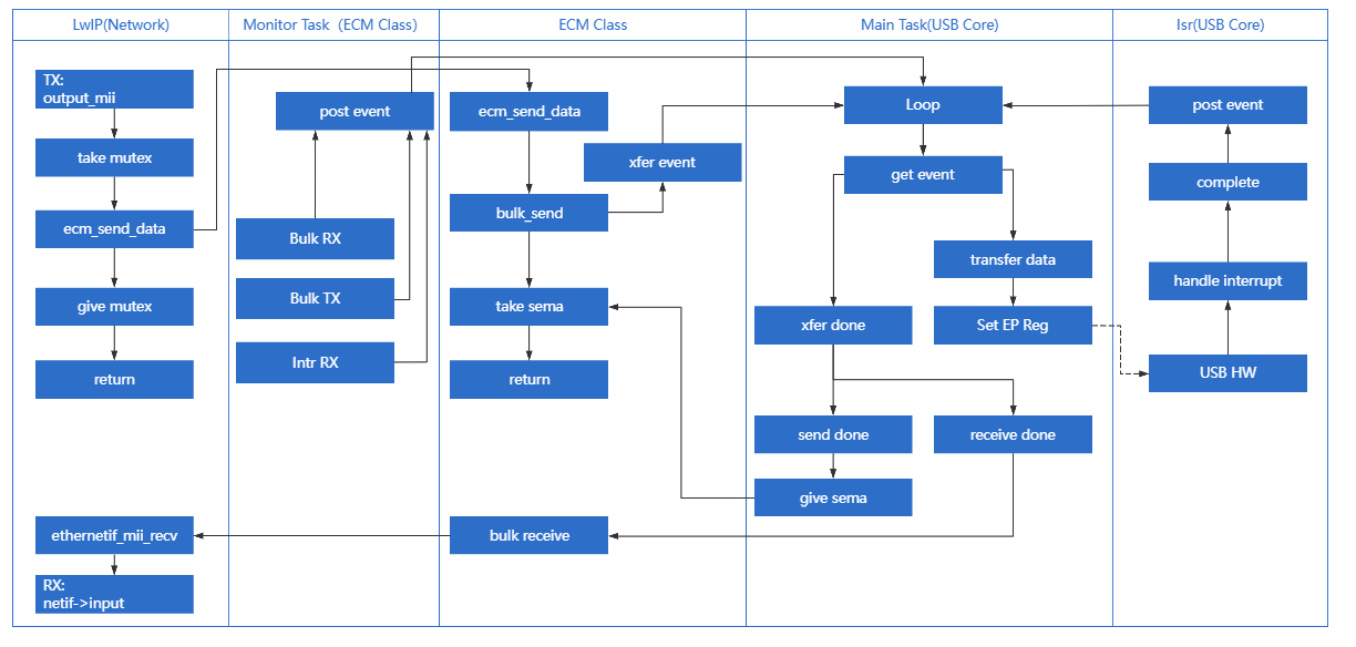
The system is divided into several core modules based on functional responsibilities:
Network Protocol Stack Adapter (LwIP)
Responsible for Encapsulation & Decapsulation of Network Layer Packets.
Acting as the interface layer between the USB driver and the TCP/IP stack (LwIP), it functions effectively as the Data Link Layer:
TX (Data Producer): Receives PBUF data packets from LwIP and converts them into USB transfer requests.
RX (Data Consumer): Receives Ethernet frames reported by the USB lower layer, encapsulates them into PBUFs, and submits them to LwIP for upper-layer protocol processing.
ECM Driver Architecture
The CDC ECM Host driver features a componentized design, consisting of two core components: the ECM Class Driver and the Transmission Monitor Module. These components work synergistically to handle standard protocol logic and guarantee communication link reliability.
ECM Class Driver
This module strictly adheres to the USB CDC ECM protocol specification, implementing the core business logic for Host-Device interaction. Key responsibilities include:
Enumeration & Configuration Parsing: Identifies CDC communication and data interfaces, parses device descriptors, and extracts key parameters such as the MAC address.
Network Control Management: Manages device behavior via the Control Endpoint, such as configuring Packet Filters and multicast lists.
Data Tx/Rx Abstraction: Provides standardized data transmission/reception APIs, serving as a bridge between the upper network stack (LwIP) and the underlying USB transport.
Transmission Monitor Task
This is an independent daemon task designed to enhance driver robustness in complex scenarios.
Status Polling: Periodically checks the health of all active USB Pipes.
Self-Healing Mechanism: Immediately triggers recovery processes upon detecting transmission anomalies (e.g., timeouts or blocking), ensuring automatic network connection restoration and uninterrupted communication.
Core Processing Task (Main Task)
Responsible for USB Stack Core Logic & State Machine Management.
Acting as the “brain” of the USB Host driver, the Main Task operates on an Event-Driven mechanism. Its primary responsibilities include:
State Machine Maintenance: Manages the operational states of the USB Enumeration State Machine and the CDC ECM Class Driver.
Event Handling: Responds to transfer events from the ISR or upper-layer applications.
Transfer Scheduling: Schedules URB (USB Request Block) requests and coordinates the timing logic for Control, Bulk, and Interrupt transfers.
Interrupt Service Routine (ISR)
Responsible for Hardware Interrupt Response & Low-Level Driver Abstraction.
Located at the bottom of the driver stack, it interfaces directly with the USB Host Controller hardware:
Interrupt Handling: Responds in real-time to hardware interrupts (e.g., Transfer Complete, Port Status Change, Error Interrupts).
Hardware Abstraction: Passes unified Event signals up to the Main Task while masking register operation differences between specific USB Controllers (IP Cores), ensuring hardware independence.
Class-Specific Request Implementation
The driver stack strictly adheres to the USB CDC ECM 1.2 specification, encapsulating the composition and transmission processes for core Class-Specific Requests.
The driver layer implements default logic for SetEthernetPacketFilter, SetEthernetMulticastFilters, and GetEthernetStatistic. Developers can refer to the source code to implement extensions for other request types.
Source Path: {SDK}/component/usb/host/cdc_ecm
Request Type |
Notes |
|---|---|
SetEthernetPacketFilter |
Sets the Ethernet Packet Filter Used to control which types of network packets the device receives (e.g., Unicast, Broadcast, Multicast, or Promiscuous Mode). |
SetEthernetMulticastFilters |
Sets the Multicast Address Filter When the upper network stack (e.g., IGMP) needs to listen to specific multicast groups, this request pushes the list of Multicast MAC addresses down to the device. |
GetEthernetStatistic |
Retrieves Ethernet Statistics Used to read internal statistical counters maintained by the device (e.g., successful TX/RX frames, CRC errors, dropped packets). This is typically used for network diagnostics. |
Endpoint Configuration
During the device enumeration phase, the CDC ECM Host driver parses the configuration descriptor and automatically looks up and allocates corresponding endpoint resources based on interface types to establish complete communication pipes.
Pipe Type |
Description |
|---|---|
Control IN/OUT |
Default Control Endpoint 0 (EP0). Used for sending Standard USB Requests and CDC Class-Specific Control Requests (e.g., SetEthernetPacketFilter). |
Interrupt IN |
Interrupt Input Endpoint. Belongs to the Communication Interface (CCI). Used to receive active network notifications reported by the device (e.g., NetworkConnection for cable plug/unplug status). |
Bulk IN |
Bulk Input Endpoint. Belongs to the Data Interface (DCI). Used to receive network data packets uploaded by the device (RX Data). |
Bulk OUT |
Bulk Output Endpoint. Belongs to the Data Interface (DCI). Used to send network data packets to the device (TX Data). |
API Reference
For detailed function prototypes and usage, please refer to the Device class driver API
Application Example
CDC ECM Host Driver Development Guide
This section provides a detailed guide to the full development process for the CDC ECM Host driver, covering driver initialization, hotplug management, network data transmission/reception mechanisms, and resource release.
Driver Initialization
Before using the CDC ECM Host driver, developers must define the configuration structure, register callback functions, and then sequentially call the core interfaces to start the USB Host Controller and the ECM Class Driver.
Step-by-Step Description:
Hardware Configuration: Set the USB speed mode (High Speed/Full Speed) and configure interrupt/task priorities.
Callback Registration: Define user callback structures to hook processing functions for various stages (Connect, Disconnect, Data Transfer).
Core Initialization: Call
usbh_init()to initialize the USB Core stack.Class Driver Loading: Call
usbh_cdc_ecm_init()to initialize the CDC ECM Class Driver.
/*
 * 1. Configure USB speed (High Speed or Full Speed) ,isr priority and main task priority.
 */
static usbh_config_t usbh_ecm_cfg = {
        .speed = USB_SPEED_HIGH,
        .isr_priority = USBH_ECM_ISR_PRIORITY,
        .main_task_priority = USBH_ECM_MAIN_THREAD_PRIORITY,
};
/*
 * Define USB user-level callbacks.
 */
static usbh_user_cb_t usbh_ecm_usr_cb = {
        .process = cdc_ecm_cb_process,            /* USB callback to handle class-independent events in the application */
        .validate = cdc_ecm_cb_device_check,      /* USB callback to validate a device when multiple devices are connected to a hub */
};

/*
 * 2. Define user callbacks for CDC ECM events.
 */
static usbh_cdc_ecm_state_cb_t cdc_ecm_usb_cb = {
        .init   = cdc_ecm_cb_init,                /* USB init callback */
        .deinit = cdc_ecm_cb_deinit,              /* USB deinit callback */
        .attach = cdc_ecm_cb_attach,              /* USB attach callback */
        .detach = cdc_ecm_cb_detach,              /* USB detach callback */
        .setup  = cdc_ecm_cb_setup,               /* USB setup callback */
        .bulk_send     = cdc_ecm_cb_bulk_send,    /* Data transmission complet callback */
        .bulk_received = cdc_ecm_cb_bulk_receive, /* Data transmission complet callback */
        .intr_received = cdc_ecm_cb_intr_receive, /* Data transmission complet callback */
};

int ret = 0;

/**
 * 3. Initialize USB host core driver with configuration.
 */
ret = usbh_init(&usbh_ecm_cfg, &usbh_ecm_usr_cb);
if (ret != HAL_OK) {
        return;
}

/*
 * 4. Initialize CDC ECM class driver.
 */
ret = usbh_cdc_ecm_init(&cdc_ecm_usb_cb);
if (ret != HAL_OK) {
        /* If class driver init fails, clean up the core driver */
        usbh_deinit();

        return;
}
Hotplug Event Handling
As a host, the system must robustly handle the dynamic insertion and removal of USB network adapters. The SDK natively supports hotplug mechanisms and coordinates with the LwIP protocol stack to manage network interface states (e.g., DHCP restart, default route switching).
Handling Logic:
Device Detach: Triggers a callback to release a semaphore. The application thread captures this signal, executes de-initialization, and frees heap memory.
Device Attach: The USB Core detects the device and re-executes the enumeration and driver loading process.
Link Status Maintenance: Monitors the physical link (Link Up/Down) status. Based on the status, it triggers DHCP requests or releases the IP and configures routing.
/* USB detach callback */
static usbh_cdc_ecm_state_cb_t cdc_ecm_usb_cb = {
        .detach = cdc_ecm_cb_detach,
};

/* Callback executed in main task */
static void cdc_ecm_cb_detach(void)
{
        cdc_ecm_is_ready = 0;
        usb_os_sema_give(cdc_ecm_detach_sema);
}

static int usbh_cdc_ecm_doinit(void)
{
        int status;

        status = usbh_init(&usbh_ecm_cfg, &usbh_ecm_usr_cb);
        if (status != HAL_OK) {
                RTK_LOGS(TAG, RTK_LOG_ERROR, "Host init fail %d\n", status);
                return USBH_CORE_INIT_FAIL;
        }

        status = usbh_cdc_ecm_init(&cdc_ecm_usb_cb, params);
        if (status != HAL_OK) {
                RTK_LOGS(TAG, RTK_LOG_ERROR, "Init driver fail %d\n", status);
                return USBH_CLASS_INIT_FAIL;
        }

        return HAL_OK;
}

/* Thread Context: Handle the state machine */
static void ecm_hotplug_thread(void *param)
{
        int ret = 0;

        UNUSED(param);

        for (;;) {
                usb_os_sema_take(cdc_ecm_detach_sema, USB_OS_SEMA_TIMEOUT);
                RTK_LOGS(TAG, RTK_LOG_INFO, "Hot plug\n");

                /* Stop transfer, release resource */
                usbh_cdc_ecm_deinit();
                usbh_deinit();
                usbh_cdc_ecm_tx_status_check();
                usbh_ecm_timer_unregister();

                RTK_LOGS(TAG, RTK_LOG_INFO, "Free heap size: 0x%08x\n", usb_os_get_free_heap_size());

                /* Re-init */
                ret = usbh_cdc_ecm_doinit();
                if (ret != HAL_OK) {
                        RTK_LOGS(TAG, RTK_LOG_ERROR, "Init fail %d\n", ret);
                        break;
                }
        }
}

/**
  * Get ecm device connect status
  */
int usbh_cdc_ecm_get_connect_status(void)//1 up
{
        u8 ret1 = cdc_ecm_is_ready;
        u8 ret2 = ecm_hw_connect;
        int ret = ret1 & ret2;

        return ret;;
}

/* Link Status Task */
static void ecm_link_change_thread(void *param)
{
        u8 *mac;
        u32 dhcp_status = 0;
        u8 link_is_up = 0;
        eth_state_t ethernet_unplug = ETH_STATUS_IDLE;

        UNUSED(param);
        RTK_LOGS(TAG, RTK_LOG_INFO, "Enter link status task!\n");

        cdc_ecm_do_init();

        while (1) {
                link_is_up = usbh_cdc_ecm_get_connect_status();

                if (1 == link_is_up && (ethernet_unplug < ETH_STATUS_INIT)) {   // unlink -> link
                        RTK_LOGS(TAG, RTK_LOG_INFO, "Do DHCP\n");

                        ...

                        dhcp_status = LwIP_IP_Address_Request(NETIF_ETH_INDEX);
                        if (DHCP_ADDRESS_ASSIGNED == dhcp_status) {
                                netifapi_netif_set_default(pnetif_eth); //Set default gw to ether netif
                                RTK_LOGS(TAG, RTK_LOG_INFO, "Switch to link\n");
                        } else {
                                RTK_LOGS(TAG, RTK_LOG_INFO, "DHCP Fail\n");
                        }
                } else if (0 == link_is_up && (ethernet_unplug >= ETH_STATUS_INIT)) {   // link -> unlink
                        ethernet_unplug = ETH_STATUS_DEINIT;
                        netif_set_default(pnetif_sta);  //switch to other netif
                        RTK_LOGS(TAG, RTK_LOG_INFO, "Swicth to unlink\n");
                } else {
                        rtos_time_delay_ms(1000);
                }
        }
}
Ethernet Output Process (TX)
When the upper LwIP protocol stack has packets to send, it calls the usbh_cdc_ecm_send_data() interface provided by the USB CDC ECM Class Driver.
Process Description:
Submit Request: LwIP calls the send function; the driver layer calls
usbh_cdc_ecm_bulk_send()to submit a Bulk OUT transfer request.Wait for Completion: The driver blocks via
usb_os_sema_take(), waiting for the transfer completion semaphore.USB Transfer: The USB Core handles the low-level DMA transfer, sending data to the device.
Callback Release: Upon transfer completion, the
cdc_ecm_cb_bulk_send()callback is triggered, releasing the semaphore.Return to Upper Layer: The function acquires the semaphore and returns to LwIP, indicating the transmission is complete.
static usbh_cdc_ecm_state_cb_t cdc_ecm_usb_cb = {
        .bulk_send     = cdc_ecm_cb_bulk_send,
};

/* USB transfer finish callback */
static int cdc_ecm_cb_bulk_send(usbh_urb_state_t state)
{
        usb_os_sema_give(cdc_ecm_tx_sema);
        if (state != USBH_URB_DONE) {
                RTK_LOGS(TAG, RTK_LOG_ERROR, "BULK TX fail %d\n", state);
        }

        return HAL_OK;
}

/* Tansfer APi, used for LwIP */
int usbh_cdc_ecm_send_data(u8 *buf, u32 len)
{
        int ret;
        u8 retry_cnt = 0;

        while (1) {
                ret = usbh_cdc_ecm_bulk_send(buf, len);
                if (ret == HAL_OK) {
                        //success
                        break;
                }
                if (++retry_cnt > 100) {
                        RTK_LOGS(TAG, RTK_LOG_ERROR, "TX drop(%d)\n", len);
                        ret = HAL_ERR_UNKNOWN;
                        break;
                } else {
                        usb_os_delay_ms(1);
                }
        }

        /* *wait cdc_ecm_cb_bulk_send to give the sema */
        if (ret == HAL_OK) {
                usb_os_sema_take(cdc_ecm_tx_sema, USB_OS_SEMA_TIMEOUT);
        }

        return ret;
}
Ethernet Input Process (RX)
When the USB network adapter receives network data, it uploads it to the host via the Bulk IN endpoint.
Process Description:
Register Callback: During initialization,
ethernetif_mii_recv()is registered as the reception handler for the Class Driver.USB Reception: After the low-level driver completes a Bulk IN transfer,
cdc_ecm_cb_bulk_receive()is triggered.Data Delivery: The callback function invokes
ethernetif_mii_recv().PBUF Encapsulation: LwIP
pbufis allocated, and the received raw data is copied into the pbuf payload.Submit to Stack: The
netif->input()function is called to deliver the packet to the TCP/IP stack for processing.
static usbh_cdc_ecm_state_cb_t cdc_ecm_usb_cb = {
        .bulk_received = cdc_ecm_cb_bulk_receive,
};

report_data = ethernetif_mii_recv;

static int cdc_ecm_cb_bulk_receive(u8 *buf, u32 length)
{
        if ((report_data != NULL) && (length > 0)) {
                report_data(buf, length);
        }

        return HAL_OK;
}

void ethernetif_mii_recv(u8 *buf, u32 frame_len)
{
        struct eth_drv_sg sg_list[MAX_ETH_DRV_SG];
        struct pbuf *p, *q;
        u32 total_len = frame_len;
        struct netif *netif = pnetif_eth;

        memcpy((u8*)RX_BUFFER, buf, frame_len);

        // Allocate buffer to store received packet
        p = pbuf_alloc(PBUF_RAW, total_len, PBUF_POOL);
        if (p == NULL) {
                RTK_LOGW(TAG, "\n\r[%s]Cannot allocate pbuf to receive packet(%d)\n", __func__, total_len);
                return;
        }

        // Create scatter list
        for (q = p; q != NULL && sg_len < MAX_ETH_DRV_SG; q = q->next) {
                sg_list[sg_len].buf = (unsigned int) q->payload;
                sg_list[sg_len++].len = q->len;
        }
        rltk_mii_recv(sg_list, sg_len);

        // Pass received packet to the interface
        if (ERR_OK != netif->input(p, netif)) {
                pbuf_free(p);
        }
}
Driver Unloading
When the system shuts down or switches modes, resources should be released in the reverse order of initialization.
/* 1. Deinitialize CDC ECM class driver first */
usbh_cdc_ecm_deinit();

/* 2. Deinitialize USB host core driver */
usbh_deinit();
Usage Example
This section demonstrates how to configure the Ameba development board as a USB CDC ECM Host and access the network via an external USB-to-Ethernet Adapter.
The Ameba identifies the Dongle, obtains an IP address via DHCP, and performs Ping and iPerf tests.
Example Path: {SDK}/component/example/usb/usbh_cdc_ecm (Provides a complete design reference for developers implementing network routing features).
Configuration & Compilation
Menuconfig Configuration
In the
amebaxxx_gcc_projectdirectory, execute./menuconfig.pyand selectCDC ECMas shown below. Save and exit.
[*] Enable USB
                USB Mode (Host)  --->
[*]     CDC ECM
                        Select USB Ethernet (USB Ethernet)  --->
Compile and Flash
Execute the build command and flash the generated Image file to the development board:
cd amebaxxx_gcc_project
./build.py -a usbh_cdc_ecm
Result Verification
Start Device
Reboot the development board. The serial log should show successful initialization:
[ECM-I] USBH ECM demo start
Connect Network Adapter
Insert the USB Network Adapter into the development board and connect the Ethernet cable.
Hardware Topology:

Function Test
Query Network Status (AT+WLSTATE)
Check if the IP address has been successfully obtained. See AT+WLSTATE for details.
AT+WLSTATE

[+WLSTATE]: _AT_WLAN_INFO_
WLAN0 Status: Running
==============================
....

Interface ethernet
==============================
MAC => 00:e0:4c:58:64:18
IP  => 192.168.31.87
GW  => 192.168.31.1
MSK  => 255.255.255.0
Ping Test (AT+PING)
Test connectivity with the gateway. See Ping Test for details.
AT+PING=192.168.31.1

[+PING]: _AT_WLAN_PING_TEST_

OK

[MEM] After do cmd, available heap 2978368

#

[ping_test] PING 192.168.31.1 32(60) bytes of data

[ping_test] 32 bytes from 192.168.31.1: icmp_seq=1 time=0 ms

[ping_test] 32 bytes from 192.168.31.1: icmp_seq=2 time=0 ms

[ping_test] 32 bytes from 192.168.31.1: icmp_seq=3 time=0 ms

[ping_test] 32 bytes from 192.168.31.1: icmp_seq=4 time=0 ms

[ping_test] 4 packets transmitted, 4 received, 0% packet loss, average 0 ms
[ping_test] min: 0 ms, max: 0 ms
Uplink Input Test (RX Test)
Ameba: Server (Receiver) PC: Client (Sender) See AT+IPERF for details.
EVB:

AT+IPERF=-s,-i,1
[+IPERF]: _AT_WLAN_IPERF1_TCP_TEST_

OK

[MEM] After do cmd, available heap 2977792

#
Start TCP server! id = [0]
tcp_server_func: Create socket fd = 0
tcp_server_func: Bind socket successfully
tcp_server_func: Listen port 5001
tcp_server_func: Accept connection successfully
tcp_s: id[0] Receive 9383 KBytes in 1000 ms, 76866 Kbits/sec
tcp_s: id[0] Receive 11391 KBytes in 1000 ms, 93323 Kbits/sec
tcp_s: id[0] Receive 11400 KBytes in 1000 ms, 93393 Kbits/sec
tcp_s: id[0] Receive 11393 KBytes in 1000 ms, 93334 Kbits/sec
tcp_s: id[0] Receive 11324 KBytes in 1000 ms, 92774 Kbits/sec
tcp_s: [END] id[0] Totally receive 55040 KBytes in 5013 ms, frame_num = 38604, 89943 Kbits/sec
TCP server stopped!
PC:

C:\Users\test\Desktop>iperf-2-1-9-win.exe -c 192.168.31.87 -i 1 -t 5
------------------------------------------------------------
Client connecting to 192.168.31.87, TCP port 5001
TCP window size: 64.0 KByte (default)
------------------------------------------------------------
[  1] local 192.168.31.234 port 53419 connected with 192.168.31.87 port 5001
[ ID] Interval       Transfer     Bandwidth
[  1] 0.00-1.00 sec  9.25 MBytes  77.6 Mbits/sec
[  1] 1.00-2.00 sec  11.1 MBytes  93.3 Mbits/sec
[  1] 2.00-3.00 sec  11.1 MBytes  93.3 Mbits/sec
[  1] 3.00-4.00 sec  11.1 MBytes  93.3 Mbits/sec
[  1] 4.00-5.00 sec  11.0 MBytes  92.3 Mbits/sec
[  1] 0.00-5.01 sec  53.8 MBytes  89.9 Mbits/sec
Downlink Output Test (TX Test)
Ameba: Client (Sender) PC: Server (Receiver) See AT+IPERF for details.
EVB:

AT+IPERF=-c,192.168.31.234,-i,1,-t,5
[+IPERF]: _AT_WLAN_IPERF1_TCP_TEST_

OK

[MEM] After do cmd, available heap 2977792

#
Start TCP client! id = [0]
tcp_client_func: Server IP=192.168.31.234, port=5001
tcp_client_func: Create socket fd = 0
tcp_client_func: Connect to server successfully
tcp_c: id[0] Send 11317 KBytes in 1000 ms, 92715 Kbits/sec
tcp_c: id[0] Send 11326 KBytes in 1000 ms, 92785 Kbits/sec
tcp_c: id[0] Send 11343 KBytes in 1000 ms, 92926 Kbits/sec
tcp_c: id[0] Send 11379 KBytes in 1000 ms, 93218 Kbits/sec
tcp_c: id[0] Send 11332 KBytes in 1000 ms, 92832 Kbits/sec
tcp_c: [END] id[0] Totally send 56709 KBytes in 5001 ms, 92893 Kbits/sec
tcp_client_func: Close client socket
TCP client stopped!
PC:

Desktop>iperf-2-1-9-win.exe -s -i 1
------------------------------------------------------------
Server listening on TCP port 5001
TCP window size: 64.0 KByte (default)
------------------------------------------------------------
[  1] local 192.168.31.234 port 5001 connected with 192.168.31.87 port 56481
[ ID] Interval       Transfer     Bandwidth
[  1] 0.00-1.00 sec  11.1 MBytes  92.8 Mbits/sec
[  1] 1.00-2.00 sec  11.1 MBytes  92.8 Mbits/sec
[  1] 2.00-3.00 sec  11.1 MBytes  92.9 Mbits/sec
[  1] 3.00-4.00 sec  11.1 MBytes  93.2 Mbits/sec
[  1] 4.00-5.00 sec  11.1 MBytes  92.8 Mbits/sec
[  1] 0.00-5.00 sec  55.4 MBytes  92.9 Mbits/sec
Mass Storage Host Solution
Overview
The USB Mass Storage Class (MSC) protocol establishes a standard communication specification between a host and mass storage devices.
Ameba has implemented a complete USB MSC host protocol stack based on the official MSC protocol standards released by the USB-IF. It supports interaction with MSC devices via the SCSI (Small Computer System Interface) command set, enabling stable and high-speed file reading and writing.

Features
Supports standard MSC devices (such as U-disks, SD card readers, etc.)
The maximum supported storage capacity is 32GB
Supports read and write operations of the FAT32 file system
Supports USB hot-plug
Automatically parses descriptors and adapts to speed modes
Configurable parameters such as BULK transfer length
Application Scenarios
As a USB storage host, Ameba can mount external mass storage devices via the USB interface. By combining this with network technologies to implement various data interactive applications. For example,
Smart Network Storage / Private Cloud: Combines network technology to bridge local storage with cloud connectivity, supporting automatic bidirectional file synchronization and secure remote access based on DDNS/VPN, to build a lightweight home private cloud.
Industrial IoT Gateway: Caches sensor data or serial logs to USB storage devices in unstable network environments (e.g., mines, offshore), and automatically executes resume-from-break uploads to the cloud once connectivity is restored, ensuring the integrity and reliability of industrial data.
AI Media Library & Storage Expansion: Utilizes external storage to house massive media files or AI knowledge bases, overcoming internal Flash capacity limitations to enable local offline retrieval and low-cost functional expansion.
Hardware Security Token: During startup or privilege verification, the device scans a connected U disk for specific encrypted certificates or License files; upon successful validation, it activates advanced system privileges, acting as a physically isolated, low-cost hardware authorization lock.
Protocol Introduction
Protocol document
The USB-IF has officially released the MSC-class basic protocol and specifications for the BOT transfer protocol. During the development process, please refer to the following core documents:
For the MSC BOT transfer protocol specification, please refer to https://www.usb.org/sites/default/files/usbmassbulk_10.pdf
For the SCSI command set used in the BOT transmission process, please refer to https://www.t10.org/. The following two specifications are of primary concern:
Specification
Description
Documentation
SCSI Primary Commands (SPC)
Basic commands common to all SCSI devices
SCSI Block Commands (SBC)
Specific commands for block storage devices (hard disks, USB drives, SSDs)
Software and Hardware Architecture
The figure below illustrates the software and hardware layers that commands and data traverse between the host and the device.

Taking a read operation as an example, when a user reads a file from a U disk, the process is as follows:
Host Side:
Application Request: The user initiates a file read request within an application (e.g., File Manager).
File System Conversion: The file system converts the filename and offset into a Logical Block Address (LBA) read request and generates a standard SCSI READ command.
Protocol Encapsulation: The host MSC class driver encapsulates the SCSI command into the command packet format defined by the MSC protocol.
Hardware Transmission: The USB host controller driver transmits the data packet to the bus via the physical USB port.
Device Side:
Hardware Reception: The USB device controller receives the data packet from the physical port.
Protocol Parsing: The MSC device class driver verifies the integrity of the packet and parses the encapsulated SCSI command.
Media Access: Based on the parsed command parameters (such as LBA address and length), data is read from the underlying storage medium (e.g., an SD card).
Data and Status Return: The read data is returned to the host, followed by the command execution status response.
BOT Transmission Flow
Once the MSC device is connected to the host and enumeration is complete, if it is identified as a Mass Storage device supporting BOT (Bulk-Only Transport) mode, all subsequent data communication occurs exclusively through bulk endpoints. Bulk transfers are not strictly time-critical, ensuring maximum data integrity.
According to the MSC BOT transmission protocol specification, all transfers follow a three-stage “Command -> Data -> Status” flow:
CBW (Command Block Wrapper): Sent from the host to the device. It encapsulates the specific SCSI command (e.g., READ, WRITE, INQUIRY).
Data (Data Stage): Transfers the actual file or control data. (The direction depends on the SCSI command type; for commands without data interaction, this stage is omitted).
CSW (Command Status Wrapper): Sent from the device to the host. It reports the execution result of the previous CBW command (Success, Failure, or Phase Error).

The data transmission process is as follows:
Host Initiates Request: The host MSC class driver encapsulates the SCSI command into a CBW packet and sends it to the device via the Bulk OUT endpoint.
Device Parsing and Execution: The device receives the CBW packet, performs a validity check, and parses the SCSI command. If the CBW is valid, the device operates on the underlying physical storage medium according to the command:
Write Operation (e.g., WRITE): Receives the data stream sent by the host via the Bulk OUT endpoint and writes it to the storage medium.
Read Operation (e.g., READ): Reads data from the storage medium and transmits it back to the host via the Bulk IN endpoint.
No-Data Command (e.g., TEST UNIT READY): Skips the data stage and proceeds directly to the status stage.
Device Returns Status: After data transmission is complete (or if no data transmission is required), the device sends a CSW packet via the Bulk IN endpoint to report the command execution result to the host.
Host Confirms Completion: The host parses the received CSW packet and checks the
bCSWStatusfield to confirm whether the command was executed successfully, thereby concluding the operation.
Class-Specific Requests
Control requests for MSC devices are categorized into Standard Requests and Class-Specific Requests.
This section focuses on the Class-Specific Requests unique to the MSC BOT specification. These requests are used to implement specific storage functions. There are only two such requests:
MSC Class-Specific Request |
Requirement |
Description |
|---|---|---|
Bulk-Only Mass Storage Reset |
Mandatory |
Resets the device interface and associated endpoints. |
Get Max LUN |
Mandatory |
Queries the maximum number of Logical Units supported by the device. |
SCSI Commands
The primary MSC BOT SCSI commands are listed below:
SCSI Command |
Requirement |
Description |
|---|---|---|
INQUIRY |
Mandatory |
The first command sent by the host to query device information. |
REQUEST_SENSE |
Mandatory |
Sent by the host to retrieve detailed error information whenever a command fails. |
TEST_UNIT_READY |
Mandatory |
Checks if the device is ready. |
READ_CAPACITY(10) |
Mandatory |
Queries the capacity of the storage medium. |
READ(10) |
Mandatory |
The core command for reading data. |
WRITE(10) |
Mandatory |
The core command for writing data. |
MODE_SENSE(6) |
Optional |
Queries specific device parameters, such as caching policy or write- protection status. |
ALLOW_MEDIUM_REMOVAL |
Optional |
Used to allow or prevent medium removal, implementing the “Safely Remove Hardware” feature. |
START_STOP_UNIT |
Optional |
Used to load or eject the medium. |
VERIFY(10) |
Optional |
Requests the device to verify that specified blocks are readable without transferring data. |
READ_FORMAT_CAPACITIES |
Optional |
Provides more detailed capacity and format information than READ_CAPACITY. |
Note
For detailed information on the SCSI standard, please refer to the official documentation.
Class Driver
The USB protocol stack provides a standard MSC host class driver based on the BOT (Bulk-Only Transport) protocol, utilizing the SCSI command set.
Pipe Configuration
Count |
Description |
|---|---|
2 |
Control IN/OUT Transfer |
1 |
Bulk IN Transfer |
1 |
Bulk OUT Transfer |
Class-Specific Request Implementation
The driver implements two Class-Specific Requests for MSC.
MSC Class-Specific Request |
Description |
|---|---|
Bulk-Only Mass Storage Reset |
The host requests a reset of the transfer when a BOT transfer error occurs. |
Get Max LUN |
After the device is connected, the host queries the number of Logical Units supported by the device. |
SCSI Command Implementation
The SCSI commands implemented by the driver under the MSC BOT specification are listed below. Developers can refer to existing implementations to extend other commands.
INQUIRY
REQUEST_SENSE
TEST_UNIT_READY
READ_CAPACITY(10)
READ(10)
WRITE(10)
FatFS Disk Driver API
The class driver defines a FatFS disk driver USB_disk_Driver typed with ll_diskio_drv:
API |
Description |
|---|---|
disk_initialize |
Initializes USB disk |
disk_deinitialize |
Deinitializes USB disk |
disk_status |
Returns disk status (RES_OK/RES_ERROR) |
disk_read |
Reads data from USB disk (sector-aligned) |
disk_write |
Writes data to USB disk (requires _USE_WRITE set in FatFS) |
disk_ioctl |
Implements FatFS IO control commands:
|
API Reference
For detailed function prototypes and usage, please refer to the Driver API
Application Example
Application Design
Driver Initialization
Use the following example code to define the configuration structure and callback functions, then invoke the initialization interface to initialize the USB host core and the MSC class driver.
static usbh_config_t usbh_cfg = {
  .speed = USB_SPEED_HIGH,
  .ext_intr_enable = USBH_SOF_INTR,
  .isr_priority = INT_PRI_MIDDLE,
  .main_task_priority = 3U,
  .tick_source = USBH_SOF_TICK,
  }

static usbh_msc_cb_t usbh_msc_usr_cb = {
  .attach = usbh_msc_cb_attach,                  /* USB device attach callback */
  .setup = usbh_msc_cb_setup,                    /* USB device setup done, indicate that device is ready for bulk transfer */
};

static usbh_user_cb_t usbh_usr_cb = {
  .process = usbh_msc_cb_process
};

int ret = 0;
ret = usbh_init(&usbh_cfg, &usbh_usr_cb);   /* Initialize USB host core driver with configuration and user callback. */
if (ret != HAL_OK) {
    return;
}

ret = usbh_msc_init(&usbh_msc_usr_cb);          /* Initializes the MSC host class with MSC class user callback. */
if (ret != HAL_OK) {
    usbd_msc_disk_deinit();
    return;
}
File Read And Write
Perform file read and write operations on the device after initialization.
static rtos_sema_t msc_attach_sema;
static __IO int msc_is_ready = 0;

static int usbh_msc_cb_attach(void)
{
  RTK_LOGS(TAG, RTK_LOG_INFO, "ATTACH\n");
  rtos_sema_give(msc_attach_sema);
  return HAL_OK;
}

static int usbh_msc_cb_setup(void)
{
  RTK_LOGS(TAG, RTK_LOG_INFO, "SETUP\n");
  msc_is_ready = 1;
  return HAL_OK;
}

static int usbh_msc_cb_process(usb_host_t *host, u8 msg)
{
  UNUSED(host);

  switch (msg) {
  case USBH_MSG_DISCONNECTED:
    msc_is_ready = 0;
    break;
  case USBH_MSG_CONNECTED:
    break;
  default:
    break;
  }

  return HAL_OK;
}

static u32 filenum = 0;
static u8 *msc_wt_buf;
static u8 *msc_rd_buf;
FATFS fs;
FIL f;
int drv_num = 0;
char logical_drv[4];
char path[64] = {'0'};
u32 br;
u32 bw;

rtos_sema_create(&msc_attach_sema, 0U, 1U);

msc_wt_buf = (u8 *)rtos_mem_zmalloc(USBH_MSC_TEST_BUF_SIZE);
if (msc_wt_buf == NULL) {
  RTK_LOGS(TAG, RTK_LOG_ERROR, "Fail to alloc test buf\n");
  goto exit_deinit;
}

msc_rd_buf = (u8 *)rtos_mem_zmalloc(USBH_MSC_TEST_BUF_SIZE);
if (msc_rd_buf == NULL) {
  RTK_LOGS(TAG, RTK_LOG_ERROR, "Fail to alloc test buf\n");
  goto exit_deinit;
}

/* Register USB disk driver to fatfs*/
drv_num = FATFS_RegisterDiskDriver(&USB_disk_Driver);
if (drv_num < 0) {
  RTK_LOGS(TAG, RTK_LOG_ERROR, "Fail to register\n");
  goto exit_deinit;
}

logical_drv[0] = drv_num + '0';
logical_drv[1] = ':';
logical_drv[2] = '/';
logical_drv[3] = 0;

while (1) {
  if (msc_is_ready) {
    rtos_time_delay_ms(10);  /* Wait for MSC device is ready for class-specific communication */
    break;
  }
}

/* Mount logical drive */
if (f_mount(&fs, logical_drv, 1) != FR_OK) {
  RTK_LOGS(TAG, RTK_LOG_ERROR, "Fail to mount logical drive\n");
  FATFS_UnRegisterDiskDriver(drv_num);
  goto exit_deinit;
}

while (1) {
  if (rtos_sema_take(msc_attach_sema, RTOS_SEMA_MAX_COUNT) != RTK_SUCCESS) {
    RTK_LOGS(TAG, RTK_LOG_ERROR, "Fail to take sema\n");
    continue;                /* Wait for MSC device attach*/
  }
}

/* Construct the device file path */
strcpy(path, logical_drv);
sprintf(&path[3], "TEST%ld.DAT", filenum);

/* Open test file */
f_open(&f, path, FA_OPEN_ALWAYS | FA_READ | FA_WRITE);
/* Write the data from a buffer to an opened file */
f_write(&f, (void *)msc_wt_buf, USBH_MSC_TEST_BUF_SIZE, (UINT *)&bw);
/* Move the file pointer to the file head */
f_lseek(&f, 0);
/* Read data from an opened file to a buffer */
f_read(&f, (void *)msc_rd_buf, USBH_MSC_TEST_BUF_SIZE, (UINT *)&br);
/* Close source file */
f_close(&f);

exit_deinit:

  rtos_sema_delete(msc_attach_sema);

  if (msc_wt_buf) {
    rtos_mem_free(msc_wt_buf);
  }
  if (msc_rd_buf) {
    rtos_mem_free(msc_rd_buf);
  }

  usbh_msc_deinit();
  usbh_deinit();
  return;
Driver Deinitialization
When storage functionality is no longer needed or during system shutdown, release resources in the reverse order of initialization.
/* Deinitialize MSC host class driver. */
usbh_msc_deinit();
/* Deinitialize USB host core driver. */
usbh_deinit();
Operation method
This section introduces a complete USB Mass Storage (MSC) application example, which demonstrates how to configure the Ameba development board as a USB storage host through the MSC protocol stack.
When the development board is connected to a standard MSC device such as a U-disk supporting the FAT32 format, the host can recognize it and perform simple file read and write tests based on FatFS.
Example path: {SDK}/component/example/usb/usbh_msc. It provides a complete design reference for developers designing custom USB storage host products.
Configuration and Compilation
Menuconfig Configuration
In the
amebaxxx_gcc_projectdirectory, type./menuconfig.py, follow the steps below to selectUSBH MSC, then save and exit.- Choose `CONFIG USB --->`: [*] Enable USB USB Mode (Host) ---> [*] MSCCompilation and Flashing
Execute the compilation command and flash the generated
Imagefile to the development board:cd amebaxxx_gcc_project ./build.py -a usbh_msc
Verification
Device Startup
Reset the development board and observe the serial log; it should display the following startup message:
[MSC-I] USBH MSC demo start
[MSC-I] Register USB disk
[MSC-I] FatFS USB W/R performance test start...
Connect to Device
Connect a U-disk (formatted as FatFS) to the USB port of the development board using a OTG cable.
Recognition and Testing
The Ameba development board will identify the MSC device and perform read/write performance tests.
[USBH-A] Device attached,speed 0
[USBH-A] PID: 0x6545
[USBH-A] VID: 0x0930
[USBH-A] Address 1 assigned
[USBH-A] MFG: TOSHIBA
[USBH-A] PROD: TransMemory
[USBH-A] SN: C03FD5F7715FE3417000DE76
[USBH-A] Enum done, total 1 cfg
[USBH-A] Switch to itf: 0
[USBH-A] Class: 0x08
[USBH-A] SubClass: 0x06
[USBH-A] Protocol: 0x50
[MSC-I] ATTACH
[MSC-I] Max lun 1
[MSC-I] Lun 0
[MSC-I] SETUP
[MSC-I] Open file: 0:/TEST0.DAT
[MSC-I] W test: size 512, round 20...
[MSC-I] W rate 204.0 KB/s for 20 round @ 49 ms
[MSC-I] R test: size = 512 round = 20...
[MSC-I] R rate 476.1 KB/s for 20 round @ 21 ms
[MSC-I] W test: size 1024, round 20...
[MSC-I] W rate 540.5 KB/s for 20 round @ 37 ms
[MSC-I] R test: size = 1024 round = 20...
[MSC-I] R rate 800.0 KB/s for 20 round @ 25 ms
[MSC-I] W test: size 2048, round 20...
[MSC-I] W rate 655.7 KB/s for 20 round @ 61 ms
[MSC-I] R test: size = 2048 round = 20...
[MSC-I] R rate 1212.1 KB/s for 20 round @ 33 ms
[MSC-I] W test: size 4096, round 20...
[MSC-I] W rate 1095.8 KB/s for 20 round @ 73 ms
[MSC-I] R test: size = 4096 round = 20...
[MSC-I] R rate 1600.0 KB/s for 20 round @ 50 ms
[MSC-I] FatFS USB W/R performance test done
[MSC-I] File close OK
Audio Host Solution
Overview
The USB Audio Class (UAC) specification defines the industry standard for transmitting audio data over USB interfaces. In Host mode, the Ameba platform utilizes this protocol to identify, configure, and drive external USB audio devices.
The current UAC Host stack on the Ameba platform is optimized for Audio Playback scenarios. It integrates a UAC 1.0 compliant protocol stack (verified against USB-IF standards), abstracting external USB UAC devices into local system audio output interfaces. This solution supports plug-and-play functionality and seamlessly integrates with the system’s built-in audio processing framework, providing convenient and high-quality audio output expansion capabilities for embedded devices.
Ameba USB Audio Playback Topology

Features
The Ameba UAC Host driver is designed to deliver stable and compatible audio output. Key features include:
Broad Device Compatibility: Fully supports USB devices compliant with the UAC 1.0 standard, such as USB speakers, USB headsets, and USB-to-3.5mm audio adapters.
Automatic Enumeration & Configuration: Automatically parses device descriptors, identifies audio streaming endpoints, and establishes Isochronous transfer channels without manual intervention.
Mainstream Audio Format Support: Please refer to the Supported Audio Formats section for detailed specifications.
Deep System Integration: Exposes a unified API to upper-layer applications, effectively abstracting and masking underlying USB protocol details.
Hot-Plug Support: Supports dynamic plug-and-play and removal of USB peripherals during runtime without requiring a system reboot.
Application Scenarios
As a USB Host, the Ameba platform handles the complexity of enumerating UAC devices, parsing audio descriptors, and maintaining stable data transmission channels. This solution is ideal for embedded applications that demand high-quality audio playback with minimal development overhead, including:
Smart Audio Terminals: Devices that require voice prompts, advertisement broadcasting, or public address functionality via external UAC devices (e.g., active speakers or headphones).
Digital Signage & Kiosks: Systems that combine local storage or network streaming to play background music or multimedia commentary through high-fidelity USB audio peripherals to enhance user experience.
IoT Audio Gateways: Lightweight audio response nodes that receive audio commands or content from Wi-Fi/Cloud sources and output them through generic USB audio devices.
Protocol Introduction
The USB Audio Class (UAC) is a standard defined by the USB-IF to standardize the encapsulation and transmission of digital audio data over USB interfaces.
By adhering to the UAC standard, USB audio devices (such as USB speakers, headsets, and microphones) can be automatically identified by host systems as standard audio input/output terminals without the need for proprietary drivers. The current UAC Host implementation on the Ameba platform primarily focuses on supporting external USB audio output devices, abstracting them as local system audio playback interfaces.
Protocol Documentation
The USB-IF has published the comprehensive base protocol specification for the UAC class. During development, please refer to the following core document:
Specification Type |
Document Link |
|---|---|
UAC 1.0 (Audio Device Class Definition for Audio Devices) |
Terminology Definition
The following table defines common technical terms related to UAC 1.0 used in this document:
Term |
Description |
|---|---|
AC Interface (Audio Control Interface) |
Responsible for managing the topology of the audio device (e.g., Input/Output Terminals, Feature Units) and issuing control commands (such as volume adjustment and mute) via the Control Endpoint. |
AS Interface (Audio Streaming Interface) |
Responsible for the actual transmission of audio payload data, typically using Isochronous endpoints. An AS Interface can contain multiple Alternate Settings, each corresponding to different sample rates, bit depths, or channel configurations. |
Terminal Type |
Identifies the physical or logical attributes of an audio signal source or sink (e.g., USB Streaming Terminal represents a USB data stream, Speaker Terminal represents a physical speaker). |
Feature Unit |
A processing node within the audio topology that provides specific audio control capabilities (e.g., master volume adjustment, channel gain, mute control). |
Sample Rate / Bit Resolution |
Core parameters of the audio format. Common combinations in UAC 1.0 include 48 kHz / 16-bit, 44.1 kHz / 16-bit, etc. |
Protocol Framework
The UAC system architecture supports audio data transmission and control by defining distinct collections of interfaces. Functionally, UAC interfaces are categorized into two main types: Audio Control Interface (AC) and Audio Streaming Interface (AS).
Audio Control Interface(AC Interface)
The Host manages the overall functional behavior of the audio device through the Audio Control Interface, including operations like volume adjustment, mute control, and input source selection.
An AC interface contains a defined Topology, which describes the flow and processing of audio signals from Input Terminals to Output Terminals.
Audio Streaming Interface(AS Interface)
The Host uses the Audio Streaming Interface to transmit the actual audio payload data.
A single UAC device may contain multiple AS interfaces, each configurable to transmit audio data with different formats, sample rates, or bit depths.
Protocol Interaction Example:

Descriptor Structure
In addition to standard USB descriptors (Device, Configuration, Endpoint), UAC devices define Class-Specific Descriptors.
These descriptors are categorized based on their associated interface into Class-Specific Audio Control (AC) descriptors and Class-Specific Audio Streaming (AS) descriptors.
Descriptor Topology
Device Descriptor
└── Identifies basic device information (USB Version 1.10)

Configuration Descriptor
├── Contains total length of the entire configuration, power supply information, etc.
│
├── Audio Control (AC) Interface Descriptor (Interface 0)
│       ├── Standard Interface Descriptor (AlternateSetting 0, Control Class)
│       └── Class-Specific Descriptor Collection
│               ├── Audio Control Interface Header (declares UAC version)
│               ├── Input Terminal (source of audio stream)
│               ├── Feature Unit (volume/mute controls, etc.)
│               ├── Output Terminal (destination of audio stream)
│               ├── Input Terminal (source of audio stream)
│               ├── Feature Unit (volume/mute controls, etc.)
│               └── Output Terminal (destination of audio stream)
│
├── Audio Streaming (AS) Interface Descriptor (Interface 1)
│       ├── Alternate Setting 0: Control transfer active state (control transfer only)
│       │
│       ├── Alternate Setting 1: Data transfer active state (with data endpoint)
│       │ ├── Standard Interface Descriptor (Interface 1, Streaming Class)
│       │ ├── Class-Specific AS Interface (associated USB streaming terminal)
│       │ ├── Format Descriptor (audio format:channel, bit width and frequency)
│       │ ├── Standard Endpoint Descriptor (ISO OUT endpoint)
│       │ └── Class-Specific Endpoint Descriptor (no special control)
│       │
│       ├── Alternate Setting 2
│       │ ...... Can configure multiple different setting as needed
│
└── Audio Streaming (AS) Interface Descriptor  (Interface 2)
        ├── Alternate Setting 0: Control transfer active state (control transfer only)
        │
        ├── Alternate Setting 1: Data transfer active state (with data endpoint)
        │ ├── Standard Interface Descriptor (Interface 2, Streaming Class)
        │ ├── Class-Specific AS Interface (associated USB streaming terminal)
        │ ├── Format Descriptor (audio format:channel, bit width and frequency)
        │ ├── Standard Endpoint Descriptor (ISO IN endpoint)
        │ └── Class-Specific Endpoint Descriptor (no special control)
        │
        ├── Alternate Setting 2
        │ ...... Can configure multiple different setting as needed
UAC Audio Control (AC) Interface Descriptor
Audio Control Interface Header
Audio Control Interface Header Descriptor
├── bLength            : 1 byte  → Total descriptor length (typically 9 + bInCollection × 1)
├── bDescriptorType    : 1 byte  → 0x24 (CS_INTERFACE)
├── bDescriptorSubtype : 1 byte  → 0x01 (HEADER)
├── bcdADC             : 2 bytes → Audio Device Class Specification Release Number (0x0100)
├── wTotalLength       : 2 byte  → Total number of bytes for all AC descriptors (including this header and all Unit/Terminal descriptors)
├── baInterfaceNr(1)   : 1 byte  → Interface number of the first AudioStreaming or MIDIStreaming interface in the Collection.
│    ⋮
└── baInterfaceNr(N)   : 1 byte  → Interface number of the last AudioStreaming or MIDIStreaming interface in the Collection.
Input Terminal Descriptor
Clock Source Descriptor
├── bLength            : 1 byte  → Total descriptor length (fixed = 12)
├── bDescriptorType    : 1 byte  → 0x24 (CS_INTERFACE)
├── bDescriptorSubtype : 1 byte  → 0x0A (Clock Source)
├── bTerminalID        : 1 byte  → Constant uniquely identifying the Terminal within the audio function.
├── wTerminalType      : 2 bytes → Constant characterizing the type of Terminal.
├── bAssocTerminal     : 1 byte  → D of the Output Terminal to which this Input Terminal is associated.
├── bNrChannels        : 1 byte  → Number of logical output channels in the Terminal’s output audio channel cluster.
├── wChannelConfig     : 2 bytes → Describes the spatial location of the logical channels.
├── iChannelNames      : 1 byte  → Index of a string descriptor, d
└── iTerminal          : 1 byte  → String descriptor index
Feature Unit Descriptor
Feature Unit Descriptor
├─ bLength                : 1 byte   → otal descriptor length in bytes = 7+(ch+1)*n
├─ bDescriptorType        : 1 byte   → = 0x24 (CS_INTERFACE)
├─ bDescriptorSubtype     : 1 byte   → = 0x06 (FEATURE_UNIT)
├─ bUnitID                : 1 byte   → Unique ID of this Feature Unit
├─ bSourceID              : 1 byte   → ID of the connected Source Unit or Terminal
├─ bControlSize           : 1 byte   → Size in bytes of an element of the bmaControls() array: n
├─ bmaControls[0]         : n bytes  → A bit set to 1 indicates that the mentioned Control is supported for master channel
├─ bmaControls[1]         : n bytes  → A bit set to 1 indicates that the mentioned Control is supported for logical channel1
│    ⋮
├─ bmaControls[N]         : n bytes  → A bit set to 1 indicates that the mentioned Control is supported for logical channel ch
└─ iFeature               : 1 byte   → String descriptor index
Output Terminal Descriptor
Output Terminal Descriptor
├─ bLength                : 1 byte   → Total descriptor length (fixed = 9 bytes)
├─ bDescriptorType        : 1 byte   → 0x24 (CS_INTERFACE)
├─ bDescriptorSubtype     : 1 byte   → 0x03 (OUTPUT_TERMINAL)
├─ bTerminalID            : 1 byte   → Unique ID of this terminal
├─ wTerminalType          : 2 bytes  → Terminal type
│                           ├─ 0x0301 = Speaker
│                           ├─ 0x0302 = Headphones
│                           ├─ 0x0603 = SPDIF
│                           └─ Other values refer to Appendix B
├─ bAssocTerminal         : 1 byte   → Associated Input Terminal ID
├─ bSourceID              : 1 byte   → ID of the connected Source Unit or Terminal
└─ iTerminal              : 1 byte   → String index for describing this terminal
Audio Streaming Interface Descriptor
Class-Specific AS Interface Descriptor
Class-Specific AS Interface Descriptor
├─ bLength                : 1 byte   → Fixed as 0x07 (7 bytes)
├─ bDescriptorType        : 1 byte   → 0x24(CS_INTERFACE)
├─ bDescriptorSubtype     : 1 byte   → 0x01(AS_GENERAL)
├─ bTerminalLink          : 1 byte   → Associated Terminal ID (Input or Output Terminal)
├─ bDelay                 : 1 bytes  → Delay introduced by this interface (in number of frames)
└─ wFormatTag             : 2 byte   → Audio data format (e.g., 0x0001 = PCM)
Audio Streaming Format Type Descriptor
Audio Streaming Format Type Descriptor
├─ bLength            : 1 byte   → Total length of descriptor in bytes (8 + (num_freq × 3))
├─ bDescriptorType    : 1 byte   → = 0x24(CS_INTERFACE)
├─ bDescriptorSubtype : 1 byte   → = 0x02(FORMAT_TYPE)
├─ bFormatType        : 1 byte   → = 0x01(FORMAT_TYPE_I)
├─ bNrChannels        : 1 byte   → Number of channels (e.g., 2)
├─ bSubslotSize       : 1 byte   → Container size for each audio sample (in bytes)
│                                   • Typical values: 1, 2, 3, 4
├─ bBitResolution     : 1 byte   → Number of valid bits in each sample(≤ bSubslotSize × 8)
├─                                  • Example: 16 represents 16-bit PCM
├─ bSamFreqType       : 1 byte   → sampling frequency count
└─ tSamFreq(n)        : 3×n byte → Sample rates in little-endian 3-byte format
Note
For detailed field definitions, please refer to the official USB-IF UAC Protocol Specification.
Class-Specific Requests
Control requests sent by the UAC Host to the device are categorized into Standard Requests and Class-Specific Requests.
This section primarily introduces Class-Specific Requests, which are unique to UAC and are used to implement specific audio device functions. These include Audio Control Requests (targeting the AC interface) and Audio Streaming Requests (targeting the AS interface).
Audio Control Requests (AC Requests)
Audio Control Requests are class-specific control transfers sent by the Host via Endpoint 0. They are used to dynamically configure and manage audio functions within the USB audio device.
Term |
Requirement |
Description |
|---|---|---|
Mute Control Request |
Optional |
Manipulates the Mute Control within a Feature Unit of the Audio Function. |
Volume Control Request |
Optional |
Manipulates the Volume Control within a Feature Unit of the Audio Function. |
Mixer Unit Control Request |
Optional |
Manipulates controls within a Mixer Unit of the Audio Function. |
Selector Unit Control Request |
Optional |
Manipulates controls within a Selector Unit of the Audio Function. |
Processing Unit Control Request |
Optional |
Manipulates controls within a Processing Unit of the Audio Function. |
Extension Unit Control Request |
Optional |
Manipulates controls within an Extension Unit of the Audio Function. |
Audio Streaming Requests (AS Requests)
Audio Streaming Requests are class-specific control transfers initiated by the Host via Endpoint 0. They are core requests used for configuring and managing parameters related to the audio data stream, focusing on stream establishment, parameter configuration, and state management.
Term |
Requirement |
Description |
|---|---|---|
Interface Control Request |
Optional |
Manipulates controls within an Audio Streaming Interface of the Audio Function. |
Endpoint Control Request |
Optional |
Describes requests supported by the Audio Function for its Audio Streaming endpoints. |
Data Transmission Format
UAC audio data streams typically use Linear PCM encoding and are encapsulated in a Multi-Channel Interleaved format. The specific data arrangement depends on the number of channels and bit depth.
For more details on supported formats, please refer to the Supported Audio Formats section.
2-Channel Interleaved Data Example:

4-Channel Interleaved Data Example:

N-Channel Interleaved Data Example:

Note
hannel Alignment Rule:
The UAC protocol typically requires the number of transmitted channels to be a power of 2 (e.g., 2, 4, 8, 16, etc.).
If the actual number of physical channels (e.g., 10 channels) does not conform to this rule, it must be rounded up to the nearest power of 2 (e.g., configured as 16 channels) for transmission, with the excess channel slots filled with invalid data (padding).
Class Driver
This section details the internal architecture of the USB Host UAC 1.0 driver stack, the responsibilities of key modules, support for class-specific requests, and the allocation strategy for underlying channel resources.
Driver Framework
The USB Host UAC 1.0 driver stack adopts a layered modular design, facilitating efficient interaction between the audio subsystem and the USB hardware controller through clearly defined interfaces. The architecture is specifically optimized for real-time Isochronous Transfer (ISOC) processing to ensure the stable output of high-fidelity audio streams.
The system is organized from top to bottom into the following core functional modules:
Audio Adapter Layer
Acting as middleware between the USB driver and the upper-layer audio framework, this layer is primarily responsible for:
Write Operations: Functioning as a data producer, it reads PCM data from the upper-layer audio buffer and writes it into the UAC Class Driver’s ring buffer.
Control Interaction: Maps upper-layer application operations, such as volume adjustment and mute toggling, to the corresponding UAC Class Driver control APIs.
UAC Class Driver Architecture
This is the core component of the UAC implementation, composed of protocol handling logic and Ringbuffer Management.
Enumeration & Configuration Parsing: Automatically identifies Audio Control (AC) and Audio Streaming (AS) interfaces, parsing parameters such as Terminal Types, Feature Units, sample rates, and bit depths.
Stream Management: Dynamically selects the appropriate Alternate Setting for the AS interface based on target audio parameters and activates the corresponding Isochronous OUT endpoint.
Buffer Scheduling: Maintains a ring buffer to handle data packetization and scheduling, ensuring a continuous, jitter-free data supply.
Protocol Encapsulation: Encapsulates standard USB requests and UAC class-specific requests (e.g., SET_CUR) to control the device.
USB Core Driver
Handles real-time hardware interrupts, standard USB enumeration, transfer management, and low-level physical data transmission scheduling.
Core Interaction Interfaces
The UAC Host Class Driver serves as a bridge within the system architecture. Its implementation logic revolves around three core interaction interfaces:
Host Class Driver Callback API: The class driver interacts with the underlying USB Core by defining and registering a standard usbh_class_driver_t structure.
Application-Facing Callback API: The class driver provides an asynchronous event notification mechanism to upper-layer applications via the usbh_uac_cb_t callback structure.
Application-Facing API: When the application layer calls these APIs, the driver switches its internal state machine to initiate data transmission scheduling.
Driver Callback Mechanism:

Init and Deinit the Class Driver
These functions manage memory resource allocation and deallocation, as well as the registration and deregistration of the class driver with the USB Core.
usbh_uac_init() is the top-level function for loading the UAC Host Class Driver. It performs the following tasks:
Save Callbacks: Stores the user-provided callback functions and invokes the user’s
initcallback.Save Parameters: Saves the user-configured frame count
frame_cntfor the ring buffer.Allocate Memory: Allocates memory buffers for control transfers and TX audio transmission.
Register Driver: Calls
usbh_register_class()to register the UAC class driver with the USB Host Core.
Example:
int usbh_uac_init(usbh_uac_cb_t *cb, int frame_cnt)
{
    /* 1. Save the frame count param */
    uac->frame_cnt = frame_cnt;

    /* 2. Allocate memory */
    uac->audio_ctrl_buf = (u8 *)usb_os_malloc(UBSH_UAC_AUDIO_CTRL_BUF_MAX_LEN);
    uac->isoc_tx_buf = (u8 *)usb_os_malloc(USBH_UAC_ISOC_BUF_LENGTH);

    /* 3. Save the user callback and call the user's ``init`` callback */
    if (cb != NULL) {
      uac->cb = cb;
      if (cb->init != NULL) {
        ret = cb->init();
        if (ret != HAL_OK) {
          RTK_LOGS(TAG, RTK_LOG_ERROR, "User init err %d\n", ret);
          return ret;
        }
      }
    }

    /* 4. Register class driver*/
    usbh_register_class(&usbh_uac_driver);

    return HAL_OK;
}
usbh_uac_deinit() is the top-level function used to unload the UAC host class driver, responsible for cleaning up resources.
Call
usbh_uac_stop_play()to notify the UAC class driver to stop data transmission.Call
usbh_unregister_class()to unregister the UAC class driver.Invokes the user’s
deinitcallback to notify the application layer.Forcibly closes all open pipes (ISOC OUT) if the device is currently connected.
Frees all previously allocated memory, including the ring buffer, descriptor parsing memory, etc.
Example:
int usbh_uac_deinit(void)
{
   /* 1. Stop ISOC data transmission */
   usbh_uac_stop_play();

  /* 2. Unregister class driver*/
  usbh_unregister_class(&usbh_uac_driver);

  /* 3. Call the user's ``deinit`` callback  */
  if ((uac->cb != NULL) && (uac->cb->deinit != NULL)) {
    uac->cb->deinit();
  }

  /* 4. Close all open pipes */
  usbh_uac_deinit_all_pipe();

  /* 5. Free ringbuffer */
  usbh_uac_ep_buf_ctrl_deinit(&(uac->isoc_out));

  /* 6. Free memory */
  if (uac->audio_ctrl_buf != NULL) {
      usb_os_mfree(uac->audio_ctrl_buf);
      uac->audio_ctrl_buf = NULL;
  }
  if (uac->isoc_tx_buf != NULL) {
      usb_os_mfree(uac->isoc_tx_buf);
      uac->isoc_tx_buf = NULL;
  }
  /****/

  return ret;
}
Attach & Detach Handling
Callbacks are triggered when the USB Core detects the insertion or removal of a device matching the UAC class.
usbh_uac_cb_attach is a critical step in device enumeration, responsible for parsing interface descriptors and allocating pipe resources:
Find AC Interface: Parses and retrieves audio control information, including volume ranges and mute capabilities.
Find AS Interface: Parses and retrieves audio format information and endpoint descriptors.
Open Pipe: Allocates and opens the ISOC OUT pipe based on the retrieved descriptor information.
Initialize State Machine: Sets the initial state to UAC_STATE_GET_MUTE to prepare for fetching audio information.
Notify Application: Calls the user attach callback to inform the application layer of the connection status.
static int usbh_uac_cb_attach(usb_host_t *host)
{
  /* 1. Parse descriptors to get AC and AS information */
  status = usbh_uac_parse_interface_desc(host);
  if (status) {
    return status;
  }

  /* 2. Open the pipe for steaming transfer */
  if (uac->as_isoc_out) {
      as_itf = uac->as_isoc_out;
      as_itf->choose_alt_idx = 0;

      pipe = &(as_itf->pipe);
      ep_desc = &(as_itf->itf_info_array[as_itf->choose_alt_idx].ep_desc);

      usbh_open_pipe(host, pipe, ep_desc);
  }

  /* 3. Initialize the state machine */
  uac->ctrl_state = UAC_STATE_GET_MUTE;

  /* 4. Notify the user layer */
  if ((uac->cb != NULL) && (uac->cb->attach != NULL)) {
      uac->cb->attach();
  }
  return HAL_OK;
}
usbh_uac_cb_detach is called when the device is removed. It is responsible for notifying the upper-layer application that the device has been removed.
static int usbh_uac_cb_detach(usb_host_t *host)
{
  /* 1. Notify the user layer */
  if ((uac->cb != NULL) && (uac->cb->detach != NULL)) {
      uac->cb->detach();
  }

  /* 2. Reset xfer status */
  uac->xfer_state = UAC_STATE_IDLE;

  return HAL_OK;
}
Class Driver State Machine
The usbh_uac_cb_process callback is the core state machine handler for the UAC class on the Host side.
Unlike the Device side, which passively responds to requests, the Host driver must actively maintain the device state. Its primary responsibilities are managing the lifecycle state of the class driver and dispatching transfer tasks.
State Management and Scheduling
usbh_uac_cb_process manages the scheduling of control transfers (e.g., sample rate configuration) and data transfers based on the current class driver state.
State Enum |
Description |
Key Action |
|---|---|---|
IDLE |
Idle State |
Waits for user commands or data transfer requests. |
TRANSFER |
Data Transferring |
Dispatches tasks to specific TX/RX handlers based on pipe numbers. |
ERROR |
Error State |
Attempts to Clear Feature on endpoints to restore communication. |
Transfer Dispatch Example
When in the TRANSFER state, processing is dispatched to specific transfer handlers based on the pipe ID triggering the event.
Example:
case UAC_STATE_TRANSFER:
     /* Distribute transmission tasks according to pipe numbers */
     if (event.msg.pipe_num == 0) {
         ret = usbh_uac_ctrl_setting(host, 0);      // Handle ctrl message transfer
     }
  break;
Error Recovery
If an error occurs during state processing, the driver attempts to send a Clear Feature request and reset to the IDLE state.
Example:
/* ... Error state ... */
case UAC_STATE_ERROR:
    /* Error recovery mechanism */
    ret = usbh_ctrl_clear_feature(host, 0x00U);
    if (ret == HAL_OK) {
        uac->xfer_state = UAC_STATE_IDLE;
    }
break;
Data Transfer Processing
UAC data transfer is categorized into two types: Audio Control Transfer and Audio Streaming Transfer .
Audio Control Transfer
Responsible for managing the functional behavior of the audio device. The driver implements a state machine flow to handle configuration requests in the following sequence:
case UAC_STATE_SET_OUT_ALT:
    ret = usbh_uac_process_set_out_alt(host);
    if (ret == HAL_OK) {
        uac->ctrl_state = UAC_STATE_SET_OUT_FREQ;
    } else if (ret != HAL_BUSY) {
        RTK_LOGS(TAG, RTK_LOG_ERROR, "OUT alt err\n");
        uac->ctrl_state = UAC_STATE_SET_OUT_FREQ;
    }
    break;
case UAC_STATE_SET_OUT_FREQ:
    ret = usbh_uac_process_set_out_freq(host);
    if (ret == HAL_OK) {
        uac->ctrl_state = UAC_STATE_CTRL_IDLE;
        ret_status = HAL_OK;
    } else if (ret != HAL_BUSY) {
        RTK_LOGS(TAG, RTK_LOG_ERROR, "OUT freq err\n");
        uac->ctrl_state = UAC_STATE_CTRL_IDLE;
        ret_status = HAL_OK;
    }
    break;
case UAC_STATE_SET_MUTE:
    ret = usbh_uac_process_set_mute(host);
    if (ret == HAL_OK) {
        uac->ctrl_state = UAC_STATE_CTRL_IDLE;
        ret_status = HAL_OK;
    } else if (ret != HAL_BUSY) {
        RTK_LOGS(TAG, RTK_LOG_ERROR, "Set mute err\n");
        uac->ctrl_state = UAC_STATE_CTRL_IDLE;
        ret_status = HAL_OK;
    }
    break;
case UAC_STATE_SET_VOLUME:
    ret = usbh_uac_process_set_volume(host);
    if (ret == HAL_OK) {
        uac->ctrl_state = UAC_STATE_CTRL_IDLE;
        ret_status = HAL_OK;
    } else if (ret != HAL_BUSY) {
        RTK_LOGS(TAG, RTK_LOG_ERROR, "Set vol err\n");
        uac->ctrl_state = UAC_STATE_CTRL_IDLE;
        ret_status = HAL_OK;
    }
    break;
Audio Streaming Transfer (ISOC):
To ensure real-time performance and low latency for audio streams, the UAC Class Driver utilizes USB hardware interrupt mechanisms (Start of Frame SOF or Transfer Completed) to precisely trigger the scheduling of the next frame of data.
Completed Interrupt: Triggered when the current data has been successfully sent to the bus.
Compact Scheduling: When the endpoint transfer interval (bInterval) is 1 (transmission required every frame), the driver maximizes bandwidth utilization and minimizes latency by immediately filling and submitting the request for the next frame within the Completed callback of the previous frame.
SOF (Start Of Frame) Interrupt: Triggered at the start of each USB frame.
Interval Scheduling: When the endpoint transfer interval (bInterval) is greater than 1 (transmission every N frames), the driver uses the SOF interrupt counter to track frame numbers. Once the scheduled interval is reached, it immediately prepares and submits the next data transfer request.
Code Example (Completed Callback Logic):
static usbh_class_driver_t usbh_uac_driver = {
    .completed = usbh_uac_cb_completed,
};

static int usbh_uac_cb_completed(usb_host_t *host, u8 pipe_num)
{
    u32 cur_frame = usbh_get_current_frame_number(host);

    if (pdata_ctrl->next_xfer == 1) {
        /* Check if this is the audio streaming pipe */
        if ((uac->as_isoc_out) && (pipe_num == uac->as_isoc_out->pipe.pipe_num)) {
            pipe->xfer_state = USBH_EP_XFER_IDLE;

            /* If ring buffer has data, prepare next transfer */
            if (!usb_ringbuf_is_empty(&(pdata_ctrl->buf_manager))) {

                /* Trigger next xfer logic: check if interval is met */
                if (usbh_uac_frame_num_dec(usbh_uac_frame_num_inc(cur_frame, 1), pipe->frame_num) >= pipe->ep_interval) {
                    usbh_uac_isoc_out_process_xfer(host, cur_frame);
                } else {
                    /* Wait for next SOF if interval not met yet */
                    pipe->xfer_state = USBH_EP_XFER_WAIT_SOF;
                }
            } else {
                /* Buffer empty, go idle */
                pipe->xfer_state = USBH_EP_XFER_IDLE;
            }
        }
    }

    return HAL_OK;
}
Code Example (SOF Callback Logic):
static usbh_class_driver_t usbh_uac_driver = {
    .sof = usbh_uac_cb_sof,
};

/**
  * @brief  SOF (Start of Frame) callback handler for UAC.
  *         Responsible for scheduling ISOC transfers when bInterval > 1.
  */
static int usbh_uac_cb_sof(usb_host_t *host)
{
    u32 cur_frame = usbh_get_current_frame_number(host);

    /* Check if audio streaming is active */
    if (pdata_ctrl->next_xfer == 1) {
        /* Check Condition 1: Standard Interval Check
                Has the time elapsed since the last transfer met the endpoint interval? */
        /* Check Condition 2: Pre-scheduling (Lookahead)
               If the previous transfer finished early (state is WAIT_SOF), check if the
               NEXT frame (cur_frame + 1) will hit the interval target.
               This allows preparing data slightly ahead of time. */
        if ((usbh_get_elapsed_frame_cnt(host, pipe->frame_num) >= pipe->ep_interval) ||
            ((pipe->xfer_state == USBH_EP_XFER_WAIT_SOF) &&
             (usbh_uac_frame_num_dec(usbh_uac_frame_num_inc(cur_frame, 1), pipe->frame_num) >= pipe->ep_interval))) {
            /* Execute transfer if either condition is met */
            usbh_uac_isoc_out_process_xfer(host, cur_frame);
        }
    }

    return HAL_OK;
}
Application-Facing APIs
These interfaces are provided to the upper-layer application for information retrieval, device configuration, and data transmission.
Configuration APIs
usbh_uac_get_alt_setting():Returns a list of all audio formats supported by the current UAC device.usbh_uac_set_alt_setting():Selects a format from the supported list and configures the device via the UAC class driver.usbh_uac_set_volume():Sets the volume. Parameter range is 0-100; the driver converts this to a dB value sent to the device.usbh_uac_set_mute():Enables or disables mute mode.
Data Streaming APIs
usbh_uac_write():Writes PCM data into the driver’s internal ring buffer. The class driver automatically fragments large data packets into smaller packets that fit the USB frame size based on the audio format.usbh_uac_start_play():Initiates the playback process; the driver begins extracting data from the ring buffer and sending it.usbh_uac_stop_play():Stops playback and terminates the ISOC OUT transmission.
Class-Specific Request Implementation
The driver stack includes built-in encapsulation for core requests defined by the USB Audio Class 1.0 specification. The current implementation focuses on Audio Playback scenarios and enables control requests targeting Feature Units by default.
Developers can view the source code at {SDK}/component/usb/host/uac and extend it to support additional request types as needed.
Request Type |
Note |
|---|---|
Mute Control |
Sends a SET_CUR request to the Mute Control Selector of a Feature Unit to mute/unmute audio. |
Volume Control |
Sends a SET_CUR request to the Volume Control Selector of a Feature Unit to set gain values. |
Channel Configuration
During the device enumeration phase, the driver parses the configuration descriptor. When an Audio Streaming (AS) Interface is detected as active, the driver automatically requests the corresponding USB pipe resources.
Pipe Type |
Usage Description |
|---|---|
Control IN/OUT Pipe |
Used for standard device requests (enumeration, configuration) and UAC class-specific requests (volume, sample rate settings). |
Isochronous OUT Pipe |
Belongs to the Active Alternate Setting (typically Alt 1) of the Audio Streaming (AS) Interface. Used by the Host to send PCM audio data streams (TX Data) to the UAC device. |
API Reference
Application Example
Application Development Guide
This section details the process required to develop a complete USB UAC 1.0 Host application, covering driver initialization, hot-plug event handling, audio data writing mechanisms, and resource release strategies.
Driver Initialization
Before using the UAC 1.0 Host driver, hardware parameter configuration, callback registration, and core protocol stack initialization must be completed in the specified sequence.
Step-by-Step Description:
Hardware Configuration: Configure the USB speed mode (Full Speed) and interrupt/task priorities.
Callback Registration: Define user callback structures and mount handlers for various stages (connection, disconnection, data transmission).
Core Startup:Call
usbh_init()andusbh_uac_init()sequentially to start the protocol stack.
/*
 * 1. Configure USB speed (Full Speed) ,isr priority and main task priority.
 */
static usbh_config_t usbh_cfg = {
        .speed = USB_SPEED_FULL,
        .isr_priority = INT_PRI_MIDDLE,
        .main_task_priority = USBH_UAC_MAIN_THREAD_PRIORITY,
        .ext_intr_enable = USBH_SOF_INTR,
};
/*
 * Define USB user-level callbacks.
 */
static usbh_user_cb_t usbh_usr_cb = {
        .process = usbh_uac_cb_process,            /* USB callback to handle class-independent events in the application */
};

/*
 * 2. Define user callbacks for UAC events.
 */
static usbh_uac_cb_t usbh_uac_cfg = {
        .init   = usbh_uac_cb_init,                /* USB init callback */
        .deinit = usbh_uac_cb_deinit,              /* USB deinit callback */
        .attach = usbh_uac_cb_attach,              /* USB attach callback */
        .detach = usbh_uac_cb_detach,              /* USB detach callback */
        .setup  = usbh_uac_cb_setup,               /* USB setup callback */
        .isoc_transmitted     = usbh_uac_cb_isoc_transmitted,    /* Data transmission complet callback */
};

int ret = 0;

/**
 * 3. Initialize USB host core driver with configuration.
 */
ret = usbh_init(&usbh_cfg, &usbh_usr_cb);
if (ret != HAL_OK) {
        return;
}

/*
 * 4. Initialize UAC class driver.
 */
ret = usbh_uac_init(&usbh_uac_cfg, USBH_UAC_FRAME_CNT);
if (ret != HAL_OK) {
        /* If class driver init fails, clean up the core driver */
        usbh_deinit();

        return;
}
Hot-Plug Event Handling
The system must possess a robust hot-plug handling mechanism to cope with the dynamic removal and re-insertion of UAC devices. The SDK provides standard state machine and callback mechanisms to notify the upper-layer application.
Handling Logic:
Detach: Triggers a callback to release a semaphore. The application thread captures this, executes de-initialization, and frees heap memory.
Attach: The USB Core detects the device and re-executes the enumeration and driver loading process.
/* USB detach callback */
static usbh_uac_cb_t usbh_uac_cfg = {
        .detach = usbh_uac_cb_detach,
};

/* Callback executed in main task */
static int usbh_uac_cb_detach(void)
{
        RTK_LOGS(TAG, RTK_LOG_INFO, "DETACH\n");
        rtos_sema_give(usbh_uac_detach_sema);
        usbh_uac_is_ready = 0;
        return HAL_OK;
}

/* Thread Context: Handle the state machine */
static void usbh_uac_hotplug_thread(void *param)
{
        int ret = 0;

        UNUSED(param);

        for (;;) {
                usb_os_sema_take(usbh_uac_detach_sema, USB_OS_SEMA_TIMEOUT);
                RTK_LOGS(TAG, RTK_LOG_INFO, "Hot plug\n");

                /* Stop transfer, release resource */
                usbh_uac_deinit();
                usbh_deinit();

                rtos_time_delay_ms(10);
                RTK_LOGS(TAG, RTK_LOG_INFO, "Free heap size: 0x%08x\n", usb_os_get_free_heap_size());

                /* Re-init */
                ret = usbh_init(&usbh_cfg, &usbh_usr_cb);
                if (ret != HAL_OK) {
                        break;
                }

                ret = usbh_uac_init(&usbh_uac_cfg, USBH_UAC_FRAME_CNT);
                if (ret < 0) {
                        usbh_deinit();
                        break;
                }
        }
}
Audio Data Stream Mechanism
The UAC Class Driver utilizes a Ring Buffer mechanism to buffer audio data generated by the upper-layer application and drives continuous data transmission via SOF (Start of Frame) or Transfer Complete interrupts.
Audio Write
The upper-layer application calls the usbh_uac_write() interface to fill PCM data into the ring buffer. If the buffer is full, this function will block and wait based on the configured timeout_ms.
static int usbh_uac_write_ring_buf(usbh_uac_buf_ctrl_t *pdata_ctrl, u8 *buffer, u32 size, u32 *written_len)
{
        u32 written_size = handle->written;

        /* Fill it into the end of the data that was not completed last time to form a whole package */
        if (written_size) {
                xfer_len = usbh_uac_next_packet_size(pdata_ctrl);
                can_copy_len = xfer_len - written_size;
                copy_len = size < can_copy_len ? size : can_copy_len;

                usb_ringbuf_write_partial(handle, buffer, copy_len);
                offset += copy_len;
                *written_len += copy_len;

                if (size >= can_copy_len) {
                        size -= copy_len;
                        usb_ringbuf_finish_write(handle);
                        pdata_ctrl->sample_accum = pdata_ctrl->last_sample_accum;
                } else {
                        return 0;
                }
        }

        /* Fill the entire package in a cycle */
        do {
                if (usb_ringbuf_is_full(handle)) {
                        return 1;
                }

                xfer_len = usbh_uac_next_packet_size(pdata_ctrl);

                if (size >= xfer_len) {
                        usb_ringbuf_add_tail(handle, buffer + offset, xfer_len);

                        *written_len += xfer_len;
                        size -= xfer_len;
                        offset += xfer_len;

                        pdata_ctrl->sample_accum = pdata_ctrl->last_sample_accum;
                } else {
                        break;
                }
        } while (1);

        /* Write the remaining data at the end */
        if (size > 0) {
                if (usb_ringbuf_is_full(handle)) {
                        return 1;
                }

                usb_ringbuf_write_partial(handle, buffer + offset, size);

                *written_len += size;
        }
        return 0;
}

/* Tansfer APi, used for Audio */
u32 usbh_uac_write(u8 *buffer, u32 size, u32 timeout_ms)
{
        /* check usb status */
        if (usbh_uac_usb_status_check() != HAL_OK) {
                return 0;
        }

        /* loop to write data to the ringbuffer */
        while (written_len < size && pdata_ctrl->next_xfer) {

                if (usb_ringbuf_is_full()) {
                        if (usbh_uac_wait_isoc_with_status_check(pdata_ctrl, timeout_ms) != HAL_OK) {
                                break;
                        }
                }

                try_len = size - written_len;
                just_written = 0;

                usbh_uac_write_ring_buf(pdata_ctrl, buffer + written_len, try_len, &just_written);
                RTK_LOGS(TAG, RTK_LOG_DEBUG, "Want %msg, wrote %msg\n", try_len, just_written);

                if (just_written > 0) {
                        written_len += just_written;
                        last_zero = 0;
                } else {
                        //wait sema and retry
                        last_zero = 1;
                }
        }

        return written_len;
}
Audio Output
The underlying driver automatically retrieves data from the ring buffer via interrupt callbacks and sends it to the USB bus.
SOF Interrupt: Triggered periodically (every 1ms). It checks if the current frame number reaches the transmission Interval. If so, it retrieves data from the RingBuffer and submits the transfer.
Commplete Interrupt: Triggered after the previous transfer completes. It checks if the RingBuffer has remaining data; if so, it schedules the transmission task for the next frame.
static usbh_class_driver_t usbh_uac_driver = {
        .sof = usbh_uac_cb_sof,
        .completed = usbh_uac_cb_completed,
};

static void usbh_uac_isoc_out_process_xfer(usb_host_t *host, u32 cur_frame)
{
        if (!usb_ringbuf_is_empty(&(pdata_ctrl->buf_list))) {
                // check valid data
                pbuf = usb_ringbuf_get_head(&(pdata_ctrl->buf_list));
                if (pbuf && pbuf->buf_len > 0) {
                        pipe->frame_num = usbh_uac_frame_num_inc(cur_frame, 1);
                        pipe->xfer_buf = pbuf->buf;
                        pipe->xfer_len = pbuf->buf_len;
                        usbh_transfer_data(host, pipe);
                        pipe->xfer_state = USBH_EP_XFER_BUSY;
                }
}

static int usbh_uac_cb_sof(usb_host_t *host)
{
        /* this class right not just support isoc out */
        if (pdata_ctrl->next_xfer == 1) {
                /*
                        if cur_frame - last frame_num  >= interval, means we should trigger a xfer asap
                        if xfer_state = USBH_EP_XFER_WAIT_SOF, it means that last xfer has been done, so in sof intr, we should check whether the next frame will be the xfer frame
                */
                if ((usbh_get_elapsed_frame_cnt(host, pipe->frame_num) >= pipe->ep_interval) ||
                        ((pipe->xfer_state == USBH_EP_XFER_WAIT_SOF) &&
                         (usbh_uac_frame_num_dec(usbh_uac_frame_num_inc(cur_frame, 1), pipe->frame_num) >= pipe->ep_interval))) {
                        usbh_uac_isoc_out_process_xfer(host, cur_frame);
                }
        }
        return HAL_OK;
}

static int usbh_uac_cb_completed(usb_host_t *host, u8 pipe_num)
{
        if (pdata_ctrl->next_xfer == 1) {
                if ((uac->as_isoc_out) && (pipe_num == uac->as_isoc_out->pipe.pipe_num)) {
                        usbh_uac_isoc_out_process_complete(host);
                        if (!usb_ringbuf_is_empty(&(pdata_ctrl->buf_list))) {
                                //trigger next xfer after binterval
                                if (usbh_uac_frame_num_dec(usbh_uac_frame_num_inc(cur_frame, 1), pipe->frame_num) >= pipe->ep_interval) {
                                        usbh_uac_isoc_out_process_xfer(host, cur_frame);
                                } else {
                                        pipe->xfer_state = USBH_EP_XFER_WAIT_SOF;
                                }
                        } else {
                                /* TX ISOC OUT token only when play*/
                                pipe->xfer_state = USBH_EP_XFER_IDLE;
                        }
                }
        }

        return HAL_OK;
}
Driver Deinit
When the system shuts down or a full reset of the USB stack is required, resources must be released strictly in the reverse order: Class Driver first, then Core Driver, to avoid memory leaks or pointer errors.
/* 1. Deinitialize UAC class driver first */
usbh_uac_deinit();

/* 2. Deinitialize USB host core driver */
usbh_deinit();
Example Project Guide
This section uses the scenario of Ameba connecting to a USB Headset for audio playback to demonstrate how to configure the Ameba development board as a USB UAC 1.0 Host and output audio through an external standard USB headset.
Default Behavior: Identify UAC Device -> Configure as 48 kHz / 16-bit / 2-channels -> Loop playback of a preset PCM audio clip.
Path:
{SDK}/component/example/usb/usbh_uac, This provides a complete design reference for developers creating products such as voice announcement systems or audio gateways.
Configuration and Compilation
Menuconfig
In the
amebaxxx_gcc_projectdirectory, execute./menuconfig.py, select UAC using the steps below, and save to exit.
[*] Enable USB
                USB Mode (Host)  --->
[*]     UAC
Compile and Flash
Execute the build command and flash the generated Image file to the development board:
cd amebaxxx_gcc_project
./build.py -a usbh_uac
Result Verification
Start Device
Reset the development board and observe the serial log (Log UART). When the following log appears, the USB Host initialization is successful:
[UAC-I] USBH UAC demo start
Connect Device
Insert a UAC 1.0 compatible USB headset into the development board.
Functional Tests
Auto Play Test
Upon successful connection, the system will automatically begin audio stream transmission.
Expected Result: The preset audio clip is heard through the headphones (defaults to looping 60 times, 1 second per loop).
Note
The loop count configuration can be modified in
example_usbh_uac.c.Mute Control Test
Enter the following commands in the serial console:
uach_mute 1:Mute the headphones.
uach_mute 0:Unmute and restore sound.
Volume Control Test
Enter the following commands in the serial console:
uach_vol 10:Set volume to 10% (lower volume).
uach_vol 90:Set volume to 90% (higher volume).
Video Host Solution
Overview
The USB Video Class (UVC) protocol defines the industry standard for transmitting video data over a USB interface. In Host mode, the Ameba platform can identify and drive external USB camera devices through this protocol.
The UVC host protocol stack of the Ameba platform focuses on the Video Capture scenario. It integrates the USB-IF compliant UVC 1.5 protocol, abstracting external USB cameras as system local video input interfaces. This solution supports Plug-and-Play, can seamlessly interface with the system’s built-in video processing framework, and provides convenient, flexible visual perception extension capabilities for devices.

Features
The Ameba UVC Host driver aims to provide efficient and compatible video input capabilities. The main features are as follows:
Extensive Device Compatibility: Supports UVC-compliant USB camera devices (such as USB webcams, industrial cameras, USB microscopes).
Automatic Enumeration Configuration: Automatically parses device descriptors, identifies video streaming interfaces and control interfaces, and establishes Isochronous transmission channels.
Mainstream Video Format Support:
Compressed formats: MJPEG, H.264
Uncompressed formats: YUV
Deep System Integration: Exposes a unified API interface to upper-layer applications, shielding underlying USB transmission details.
Hot-Plug Support: Supports Plug-and-Play and dynamic removal of USB peripherals without restarting the system.
Application Scenarios
As a USB Host, Ameba is responsible for enumerating USB cameras, parsing video descriptors, and establishing a stable image data stream. This solution is suitable for embedded applications that have requirements for visual acquisition while pursuing low power consumption and rapid integration, such as:
Intelligent Monitoring and Security: Ameba captures images in real-time via USB cameras, combined with network transmission or local storage, used for home monitoring, doorbell peepholes, or industrial site surveillance.
Visual Recognition Terminals: As a front-end acquisition device for edge computing nodes, it acquires image data and passes it to subsequent AI algorithms for face recognition, QR code scanning, or object detection.
Video Calling Devices: Combined with Wi-Fi or cellular network modules, it captures user video streams through generic USB cameras to realize low-cost VoIP video intercom functions.
Protocol Introduction
The UVC (USB Video Class) protocol defines standard interfaces within the USB specification framework for implementing Control Management and Video Stream Transmission between a host and video capture devices. The host driver establishes video data channels through this protocol to achieve real-time camera preview, recording, and parameter adjustment.
Protocol Documents
USB-IF has officially released the UVC class base protocol and specifications for multiple Payload formats. Please refer to the following core documents during development:
Specification Type |
Document |
|---|---|
UVC 1.5 (Video Class Base Protocol) |
|
Payload Specs (Payload Formats) |
Contained within the USB_Video_Payload_*.pdf files in the archive above. |
Term Definition
The definitions of general UVC (USB Video Class) technical terms used in this document are as follows:
Term |
Description |
|---|---|
VC Interface (Video Control Interface) |
Video Control Interface. As the core control center of the UVC device, it manages the topology of the video device (such as the connection relationship between Units and Terminals). The host sends control requests via this interface, such as adjusting brightness, contrast, or performing Pan/Tilt/Zoom control. |
VS Interface (Video Streaming Interface) |
Video Streaming Interface. Responsible for the actual transmission of video payload data, usually using Isochronous or Bulk pipes. Each VS Interface contains specific video format information (such as YUV, MJPEG, H.264) and related frame descriptors. |
Input Terminal (IT) |
Input Terminal. The entry point where the video data stream enters the UVC function topology. Common input terminals include Camera Sensors or Composite Video Input interfaces. It represents the physical source of data. |
Output Terminal (OT) |
Output Terminal. The exit point where the video data stream leaves the UVC function topology. The most common output terminal is the USB Streaming Terminal, indicating that data will be sent to the host via the USB bus. |
Processing Unit (PU) |
Processing Unit. A processing node located after the Input Terminal, used to adjust the video image itself. It provides control capabilities over image quality, such as Brightness, Contrast, Hue, Saturation, and Sharpness. |
Extension Unit (XU) |
Extension Unit. A functional module that the UVC specification allows manufacturers to customize. Through XU, manufacturers can define specific control commands outside the standard UVC specification and access them on the host side via matching drivers or applications. |
Probe & Commit Control |
Negotiation and Commit Control. This is a critical mechanism in the process of establishing a video stream. The host first sends a “Probe” request to query the bandwidth and parameters supported by the device. After reaching an agreement, it sends a “Commit” request to lock the configuration before the video stream transmission can be started. |
Payload Header |
Payload Header. Header information in UVC video stream data packets, containing key synchronization information such as frame toggle (Frame ID), timestamp (PTS/SCR), and error flags. |
Protocol Framework
The UVC Host protocol stack adopts a layered architecture design, aiming to decouple the USB transport layer from the upper-layer video application or multimedia framework.

Component Responsibilities
Application
Located at the top layer of the architecture, responsible for specific business logic processing. Includes video preview, recording applications, or AI algorithms and network streaming services based on video streams.
Video Middleware
Acts as an abstraction layer connecting the upper and lower layers. It provides a unified data acquisition interface upwards for the application layer, shielding underlying differences; it is responsible for video stream encoding/decoding processing, format conversion, and buffer queue management.
UVC Class Driver
The core intermediate layer, implementing behaviors defined by the UVC specification:
Topology Parsing: Parses the internal topology (Unit/Terminal) of the Video Control Interface (VC) and format descriptors of the Video Streaming Interface (VS).
Stream Negotiation: Implements the Probe and Commit processes to negotiate parameters such as resolution, frame rate, and bandwidth.
Frame Reassembly and Submission: Parses the UVC Payload Header, handles frame start/end indicators (FID/EOF), reassembles scattered USB packets into complete video frames, and submits them to the middleware layer frame by frame.
USB Core & HCD (Host Controller Driver)
Underlying drivers responsible for handling USB standard enumeration, isochronous pipe management, and scheduling of underlying physical data transmission.
Communication Mechanism
Standard UVC devices aggregate the following interfaces through the Interface Association Descriptor (IAD):
Video Control Interface (VC Interface) - Topology Control
Transfer Mechanism: Based on Control Transfer over the default pipe 0 (EP0).
Core Function: Sends class-specific requests to control Unit/Terminal attributes, completing parameter negotiation via Probe and Commit processes.
Video Streaming Interface (VS Interface) - Data Pipeline
Transfer Mechanism: Uses Isochronous transfer mode to carry high-bandwidth video streams.
Features: Guarantees bandwidth and low latency (no retransmission), suitable for real-time video preview.
Descriptor Structure
In addition to standard USB descriptors (such as Device Descriptor, Configuration Descriptor, Endpoint Descriptor), UVC devices also define Class-Specific Descriptors.
These descriptors are classified into Class-Specific Video Control Interface Descriptors (VC) and Class-Specific Video Streaming Interface Descriptors (VS) based on the interface they belong to.
Descriptor Topology
Device Descriptor
└── Identifies basic device information (USB Version 2.00, Composite Device)

Configuration Descriptor
├── Contains total length, power supply (500mA), etc.
│
├── Interface Association Descriptor (IAD)
│       └── Groups Interface 0 (VC) and Interface 1 (VS) as a Video Function
│
├── Video Control (VC) Interface Descriptor (Interface 0)
│       ├── Standard Interface Descriptor (AlternateSetting 0, Video Control Class)
│       ├── Class-Specific VC Header (declares UVC version, clock frequency)
│       ├── Class-Specific Descriptor Collection (Topology)
│       │       ├── Input Terminal (Camera)
│       │       ├── Processing Unit
│       │       ├── Extension Unit (Vendor Specific Controls)
│       │       └── Output Terminal (USB Streaming)
│       └── Standard Endpoint Descriptor (Interrupt IN for Status)
│
└── Video Streaming (VS) Interface Descriptor (Interface 1)
                ├── Alternate Setting 0: Control transfer active state (negotiation only, no data endpoint)
                │ ├── Standard Interface Descriptor (Interface 1, Streaming Class)
                │ ├── Class-Specific VS Header
                │ ├── Format Descriptor
                │ │     └── Frame Descriptor (various resolutions and frame rates)
                │ ├── Format Descriptor
                │ │     └── Frame Descriptor (various resolutions and frame rates)
                │ ├── Still Image Frame Descriptor
                │ └── Color Matching Descriptor
                │
                ├── Alternate Setting 1: Data transfer active state (with data endpoint)
                │ ├── Standard Interface Descriptor (Interface 1, Streaming Class)
                │ └── Standard Endpoint Descriptor (ISO IN endpoint, e.g., Low Bandwidth)
                │
                ├── Alternate Setting 2
                │ ...... Can configure multiple different settings as needed (e.g., Medium to High Bandwidth)
                │
                └── ...... (Other Alternate Settings for different packet sizes)

Device Qualifier Descriptor
└── Device information while running in another speed mode (e.g., High Speed vs Full Speed capability)

Other Speed Configuration Descriptor
├── Configuration information while running in another speed mode
│
├── Interface Association Descriptor (IAD)
│       └── Groups Interface 0 (VC) and Interface 1 (VS) as a Video Function
│
├── Video Control (VC) Interface Descriptor (Interface 0)
│       ├── Standard Interface Descriptor (AlternateSetting 0, Video Control Class)
│       └── Class-Specific Descriptor Collection (Same Topology as main configuration)
│               ├── Input Terminal
│               ├── Processing Unit
│               ├── Extension Unit
│               └── Output Terminal
│
└── Video Streaming (VS) Interface Descriptor (Interface 1)
                ├── Alternate Setting 0: Control transfer active state (negotiation only)
                │ ├── Standard Interface Descriptor (Interface 1, Streaming Class)
                │ ├── Class-Specific VS Header
                │ ├── Format Descriptor
                │ │     └── Frame Descriptor
                │ └── Color Matching Descriptor
                │
                ├── Alternate Setting 1: Data transfer active state
                │ ├── Standard Interface Descriptor (Streaming Class)
                │ └── Standard Endpoint Descriptor (ISO IN endpoint)
                │
                └── ...... (Other alternate settings typically available in other speed modes)
UVC Video Control (VC) Interface
Video Control Interface Descriptor
Interface Header Descriptor
├── bLength            : 1 byte  → Total descriptor length (13 bytes)
├── bDescriptorType    : 1 byte  → 0x24 (CS_INTERFACE)
├── bDescriptorSubtype : 1 byte  → 0x01 (VC_HEADER)
├── bcdUVC             : 2 bytes → Video Class Specification Release Number (0x0100 = 1.00)
├── wTotalLength       : 2 bytes → Total number of bytes for all VC descriptors
├── dwClockFreq        : 4 bytes → Clock frequency in Hz (e.g., 0x02DC6C00 = 48 MHz)
├── bInCollection      : 1 byte  → Number of VideoStreaming interfaces
└── baInterfaceNr(1)   : 1 byte  → Interface number of the first VideoStreaming interface (0x01)
Input Terminal Descriptor (Camera)
Input Terminal Descriptor
├── bLength            : 1 byte  → Total descriptor length (18 bytes)
├── bDescriptorType    : 1 byte  → 0x24 (CS_INTERFACE)
├── bDescriptorSubtype : 1 byte  → 0x02 (VC_INPUT_TERMINAL)
├── bTerminalID        : 1 byte  → Unique ID of this Terminal (0x01)
├── wTerminalType      : 2 bytes → 0x0201 (ITT_CAMERA)
├── bAssocTerminal     : 1 byte  → ID of associated Output Terminal (0x00 = None)
├── iTerminal          : 1 byte  → String descriptor index
├── wObjectiveFocalMin : 2 bytes → Min focal length (0 = not supported)
├── wObjectiveFocalMax : 2 bytes → Max focal length
├── wOcularFocalLength : 2 bytes → Ocular focal length
├── bControlSize       : 1 byte  → Size of bmControls (3 bytes)
└── bmControls         : 3 bytes → Bitmap of supported controls
                                                        • D1: Auto-Exposure Mode
                                                        • D3: Exposure Time (Absolute)
                                                        • D5: Focus (Absolute)
                                                        • D9: Zoom (Absolute)
                                                        • D11: Pan (Absolute)
                                                        • D15: Tilt (Absolute)
Processing Unit Descriptor
Processing Unit Descriptor
├── bLength            : 1 byte  → Total descriptor length (11 bytes)
├── bDescriptorType    : 1 byte  → 0x24 (CS_INTERFACE)
├── bDescriptorSubtype : 1 byte  → 0x05 (VC_PROCESSING_UNIT)
├── bUnitID            : 1 byte  → Unique ID of this Unit (0x02)
├── bSourceID          : 1 byte  → ID of the source connected to this unit (0x01 = Camera IT)
├── wMaxMultiplier     : 2 bytes → Max digital zoom multiplier
├── bControlSize       : 1 byte  → Size of bmControls (2 bytes)
└── bmControls         : 2 bytes → Bitmap of supported image controls
                                                        • D0: Brightness
                                                        • D1: Contrast
                                                        • D2: Hue
                                                        • D3: Saturation
                                                        • D4: Sharpness
                                                        • D6: White Balance Temperature
Extension Unit Descriptor
Extension Unit Descriptor
├── bLength            : 1 byte  → Total descriptor length (29 bytes)
├── bDescriptorType    : 1 byte  → 0x24 (CS_INTERFACE)
├── bDescriptorSubtype : 1 byte  → 0x06 (VC_EXTENSION_UNIT)
├── bUnitID            : 1 byte  → Unique ID of this Unit (0x03)
├── guidExtensionCode  : 16 bytes→ Vendor-specific GUID (e.g., {0FB885C3-...})
├── bNumControls       : 1 byte  → Number of controls in this XU (0x05)
├── bNrInPins          : 1 byte  → Number of input pins (0x01)
├── baSourceID[1]      : 1 byte  → ID of the source connected (0x02 = PU)
├── bControlSize       : 1 byte  → Size of bmControls (4 bytes)
└── bmControls         : 4 bytes → Bitmap of supported vendor controls
Output Terminal Descriptor
Output Terminal Descriptor
├── bLength            : 1 byte  → Total descriptor length (9 bytes)
├── bDescriptorType    : 1 byte  → 0x24 (CS_INTERFACE)
├── bDescriptorSubtype : 1 byte  → 0x03 (VC_OUTPUT_TERMINAL)
├── bTerminalID        : 1 byte  → Unique ID of this terminal (0x05)
├── wTerminalType      : 2 bytes → 0x0101 (TT_STREAMING)
├── bAssocTerminal     : 1 byte  → Associated Input Terminal ID
├── bSourceID          : 1 byte  → ID of the connected Source (0x04 = XU)
└── iTerminal          : 1 byte  → String descriptor index
UVC Video Stream (VS) Interface
Video Stream Interface Descriptor
Class-Specific VS Input Header Descriptor
├── bLength            : 1 byte  → Total descriptor length (15 bytes)
├── bDescriptorType    : 1 byte  → 0x24 (CS_INTERFACE)
├── bDescriptorSubtype : 1 byte  → 0x01 (VS_INPUT_HEADER)
├── bNumFormats        : 1 byte  → Number of video formats supported (0x02)
├── wTotalLength       : 2 bytes → Total length of all VS specific descriptors
├── bEndpointAddress   : 1 byte  → Address of the ISO IN endpoint (0x81)
├── bmInfo             : 1 byte  → Capabilities (0x00)
├── bTerminalLink      : 1 byte  → ID of the Output Terminal in VC interface (0x05)
├── bStillCaptureMethod: 1 byte  → Method of still image capture (0x02)
├── bTriggerUsage      : 1 byte  → Trigger usage (0x00)
├── bControlSize       : 1 byte  → Size of control field (1 byte)
└── bmaControls(n)     : n bytes → Controls for each format
Video Stream Format Type Descriptor
Video Streaming Format Type Descriptor(MJPEG)
├── bLength            : 1 byte  → Total descriptor length (11 bytes)
├── bDescriptorType    : 1 byte  → 0x24 (CS_INTERFACE)
├── bDescriptorSubtype : 1 byte  → 0x06 (VS_FORMAT_MJPEG)
├── bFormatIndex       : 1 byte  → Index of this format (0x01)
├── bNumFrameDescriptors: 1 byte → Number of frame descriptors (0x09)
├── bmFlags            : 1 byte  → Characteristics (0x01 = Fixed Sample Size)
├── bDefaultFrameIndex : 1 byte  → Default frame index (0x01)
├── bAspectRatioX      : 1 byte  → X dimension of aspect ratio
├── bAspectRatioY      : 1 byte  → Y dimension of aspect ratio
├── bmInterlaceFlags   : 1 byte  → Interlace information (0x00 = Progressive)
└── bCopyProtect       : 1 byte  → Duplication restrictions (0x00)
Video Streaming Format Type Descriptor(Uncompressed)
├── bLength            : 1 byte  → Total descriptor length (27 bytes)
├── bDescriptorType    : 1 byte  → 0x24 (CS_INTERFACE)
├── bDescriptorSubtype : 1 byte  → 0x04 (VS_FORMAT_UNCOMPRESSED)
├── bFormatIndex       : 1 byte  → Index of this format (0x02)
├── bNumFrameDescriptors: 1 byte → Number of frame descriptors
├── guidFormat         : 16 bytes→ GUID identifying the format (YUY2: {32595559-...})
└── bBitsPerPixel      : 1 byte  → Bits per pixel (0x10 = 16 bits)
Video Stream Frame Type Descriptor
Video Streaming Frame Type Descriptor (MJPEG)
├── bLength            : 1 byte  → Total descriptor length (e.g., 34 bytes)
├── bDescriptorType    : 1 byte  → 0x24 (CS_INTERFACE)
├── bDescriptorSubtype : 1 byte  → 0x07 (VS_FRAME_MJPEG)
├── bFrameIndex        : 1 byte  → Index of this frame (0x01)
├── bmCapabilities     : 1 byte  → Still image support, etc.
├── wWidth             : 2 bytes → Frame Width (e.g., 0x0A20 = 2592)
├── wHeight            : 2 bytes → Frame Height (e.g., 0x0798 = 1944)
├── dwMinBitRate       : 4 bytes → Min Bit Rate (bps)
├── dwMaxBitRate       : 4 bytes → Max Bit Rate (bps)
├── dwMaxVideoFrameBuf : 4 bytes → Max Frame Buffer Size (bytes)
├── dwDefaultFrameInterval: 4 bytes→ Default frame interval in 100ns units
├── bFrameIntervalType : 1 byte  → 0 = Continuous, Non-0 = Discrete
└── dwFrameInterval(n) : 4×n bytes→ Discrete frame intervals supported (e.g., 33ms for 30fps)
Video Streaming Frame Type Descriptor (Uncompressed)
        ├── bLength            : 1 byte  → Total descriptor length (30 bytes)
        ├── bDescriptorType    : 1 byte  → 0x24 (CS_INTERFACE)
        ├── bDescriptorSubtype : 1 byte  → 0x05 (VS_FRAME_UNCOMPRESSED)
        ├── bFrameIndex        : 1 byte  → Index of this frame (0x01 - Default)
        ├── bmCapabilities     : 1 byte  → 0x00 (No specific capabilities set)
        ├── wWidth             : 2 bytes → Frame Width (0x0A20 = 2592)
        ├── wHeight            : 2 bytes → Frame Height (0x0798 = 1944)
        ├── dwMinBitRate       : 4 bytes → Min Bit Rate (approx 25.1 MB/s)
        ├── dwMaxBitRate       : 4 bytes → Max Bit Rate (approx 25.1 MB/s)
        ├── dwMaxVideoFrameBuf : 4 bytes → Max Frame Buffer Size (0x0099C600)
        ├── dwDefaultFrameInterval: 4 bytes→ Default interval: 400ms (2.50 fps)
        ├── bFrameIntervalType : 1 byte  → 0x01 (1 Discrete interval supported)
        └── dwFrameInterval(1) : 4 bytes → Interval 1: 400ms (2.50 fps)
Note
For detailed field definitions, please refer to the official USB-IF UVC (USB Video Class) 1.5 protocol documentation.
Note
Note: Confirm Device Capabilities at Current Speed (FS vs HS)
Please be aware that cameras often present different descriptor structures in Full Speed and High Speed modes:
Format Support Differences: Due to bandwidth limitations, certain uncompressed formats (like YUY2) may only be visible in High Speed mode. In Full Speed, the device might only support MJPEG or extremely low-resolution YUY2.
Descriptor Variations: The aforementioned VS_FRAME_UNCOMPRESSED descriptors may not exist at all when connected at Full Speed, or parameters such as resolution and frame rate may change significantly.
Class-Specific Requests
The UVC Host driver controls device behavior by sending the following requests via control pipe 0. These requests usually target specific Unit IDs or Interfaces.
Request Name |
Requirement |
Description |
|---|---|---|
SET_CUR |
Mandatory |
Sets the current attribute value. Used for Probe/Commit negotiation, or controlling PU attributes like brightness and contrast. |
GET_CUR |
Mandatory |
Gets the current attribute value. Reads negotiated parameters or current device status. |
GET_MIN / GET_MAX |
Optional |
Gets the adjustable range of an attribute. The host driver uses this range to limit input values from the application layer. |
GET_RES |
Optional |
Gets the resolution (step size) of an attribute. |
GET_DEF |
Optional |
Gets the default value of an attribute. |
GET_LEN |
Optional |
Gets the data length. |
Stream Negotiation
Before officially starting video stream transmission (Stream On), the host and device must strictly follow the UVC state machine to negotiate parameters and bandwidth; otherwise, the device may refuse to start the video stream. According to the official spec, this process consists of two main phases: Probe (Three-step Handshake) and Commit.
Stream Negotiation Timing Diagram

Detailed Core Steps
PROBE1: Initiate Negotiation (SET_CUR)
The host sends a
SET_CUR (PROBE)request to the Video Streaming Interface (VS Interface), carrying the desired video parameter structure.Purpose: The host proposes “I want this resolution, frame rate, and format”.
PROBE2: Get Feedback (GET_CUR)
The host sends a
GET_CUR (PROBE)request to read back the actual parameters supported by the device.Device Correction: If the parameters requested by the host are not supported, the device returns the closest corrected parameters.
Key Data: In the returned structure, the
dwMaxPayloadTransferSizefield is calculated and filled by the device, which is the basis for subsequent bandwidth selection.
PROBE3: Final Confirmation (SET_CUR)
The host sends the parameters read back in step 2 (which may have been corrected) to the device again via
SET_CUR (PROBE).Purpose: Both sides synchronize states, the host confirms acceptance of the device’s correction suggestions, and ends the negotiation phase.
COMMIT: Commit to Effect (SET_CUR)
After parameters are agreed upon, the host sends a
SET_CUR (COMMIT)request.Purpose: Notifies the device that “parameters are determined”.
Note
Key Parameters
In the Probe/Commit process, the host mainly relies on the following three core fields to determine the video stream configuration:
bFormatIndex: Format IndexbFrameIndex: Frame IndexdwFrameInterval: Frame Interval
Other Parameters
Whether other parameters in the structure (such as wCompWindowSize, wCompQuality, etc.) are effective or adjustable depends entirely on the actual support of the specific device. For most standard devices, usually only the above three core parameters need attention, and other parameters can maintain the default values returned by the device.
For the complete definition of the Probe and Commit Control structure and details of all fields, please refer to the official spec.
Stream Bandwidth Matching and Activation (Stream Activation)
When parameter negotiation is complete, the host needs to select appropriate hardware interface settings based on the bandwidth requirements fed back by the device to officially open the transmission pipe.
Stream Bandwidth Allocation Diagram

Match Bandwidth
The driver will traverse all Alternate Settings of the video streaming interface based on the dwMaxPayloadTransferSize value obtained during the negotiation phase.
Set Interface
Once a suitable Alternate Setting is found, the host sends the standard USB request SET_INTERFACE. This step marks the formal reservation of USB Isochronous Transfer bandwidth, and the video stream transmission begins immediately.
Note
Bandwidth Matching Principle
In isochronous transfer mode, bandwidth selection is crucial. The driver needs to follow the principle of sufficient and minimal:
Search Target: Among all Alternate Settings, look for settings where
wMaxPacketSize(endpoint maximum packet size) is greater than or equal to the negotiated valuedwMaxPayloadTransferSize.Optimal Choice: Among all settings that meet the above conditions, choose the one with the smallest
wMaxPacketSize.
If bandwidth is insufficient, it will cause data packet truncation, resulting in screen corruption or frame loss. If bandwidth is excessive, it will occupy valuable periodic USB bus bandwidth, potentially causing other devices on the bus (such as USB audio) to fail due to insufficient bandwidth.
Data Transmission Format
UVC video data is not a pure raw data stream but is encapsulated in data packets with a Payload Header. The host driver must first parse and strip this header to obtain the valid video Payload.
Payload Header Detailed Structure
Basic Header Fields
All Payload Headers start with two core bytes:
HLE (Header Length): 1 byte. Specifies the length of the entire header (in bytes), including HLE itself, BFH, and optional PTS/SCR fields.
BFH[0] (Bit Field Header): 1 byte. Bit field flags indicating attributes of subsequent data and the presence of optional fields.
BFH[0] Bit Field Definition
Bit
Name
Description
D0
FID
Frame Identifier. Used to distinguish different video frames or segments (behavior depends on video format, see below).
D1
EOF
End of Frame. Indicates whether the current packet is the last packet of a frame or segment.
D2
PTS
Presentation Time Stamp. When set to 1, indicates the header contains a 4-byte PTS field.
D3
SCR
Source Clock Reference. When set to 1, indicates the header contains a 6-byte SCR field.
D4
RES
Reserved. Usually set to 0.
D5
STI
Still Image. Set to 1 indicates the sample belongs to a static image (Stream-based formats usually set to 0).
D6
ERR
Error Bit. Set to 1 indicates an error occurred on the device during streaming.
D7
EOH
End of Header. Set to 1 indicates the end of BFH fields (i.e., no extension header).
Optional Extension Fields
PTS (4 bytes): Exists when BFH[0].D2 (PTS) is set. Represents the presentation time of the video frame.
SCR (6 bytes): Exists when BFH[0].D3 (SCR) is set. Source clock reference used for audio/video synchronization.
Video Data Transmission Formats
In the UVC specification, video data transmission formats are mainly divided into two categories: Frame-based and Stream-based. These two modes determine how the host parses video data and processes the Payload Header.
Frame-based
This is the most common mode, applicable to MJPEG, Uncompressed (YUV/NV12), and other formats.
Characteristics: Video data is strictly divided into individual independent images (frames).
Transmission Logic: The host driver focuses on “frame boundaries”, assembling a complete frame by detecting the FID toggle or EOF flag in the Payload Header.
Stream-based
Mainly used for compressed stream formats like H.264/H.265.
Characteristics: Data is treated as a continuous byte stream without a strict physical “frame” boundary concept (or the boundary is handled internally by the decoder).
Transmission Logic: The host driver is mainly responsible for transporting the data stream, usually not relying on the Payload Header to determine the start or end of a frame, but passing the data directly to the upper-layer application or decoder to parse the content.
Note
Engineering Practice: Actual Behavior of Stream-based Devices
Although the UVC specification states that Stream-based formats may not use FID and EOF to delimit boundaries, in actual engineering applications:
Device Side (Camera):
Even when outputting Stream-based formats like H.264/H.265, the vast majority of manufacturers still try to follow Frame-based rules as much as possible, marking the boundaries of data blocks (such as NAL Units or frame slices) by toggling FID or setting EOF.
Host Side (Host):
To simplify logic, most generic UVC drivers (such as Linux uvcvideo, Windows system drivers) default to uniformly slicing data packets based on FID jumps or EOF flags.
Tip
Engineering Practice: Host Driver Data Processing Mechanism
In actual engineering implementation, the UVC Host Driver adopts a unified transmission processing strategy for Frame-based and Stream-based formats, without making special distinctions for stream transmission. Its core processing logic is as follows:
Format Independence of Transport Layer:
The driver layer is only responsible for data transport and reassembly and is not aware of the specific video encoding format or stream type. Regardless of the data type declared by the device descriptor, the driver treats it as a generic data payload.
Unified Packet Assembly Mechanism:
The driver strictly relies on the FID (Frame Identifier) state toggle and EOF (End of Frame) flag bit in the Payload Header for data delimitation. The driver assembles data packets belonging to the same logical sequence into a complete Payload Buffer and submits it to the user space as one frame at the driver level.
Separation of Parsing Responsibility:
Parsing of data content is the responsibility of the Application Layer.
For example, for Stream-based formats like H.264, the Buffer submitted by the driver may contain multiple NAL Units or partial frame data, and the application layer needs to parse the stream data structure itself to obtain the actual video frames.
Class Driver
This section details the internal implementation details of the USB UVC host driver, including driver architecture, video stream management, support for class-specific requests, and pipe resource allocation schemes.
Detailed Implementation
The USB Host UVC driver stack is based on a modular design, achieving efficient interaction between the upper-layer application and the USB hardware controller through a layered architecture. This architecture ensures stable capture and processing of high-bandwidth video data and provides a flexible frame buffer management mechanism.
Its core architecture and data flow are shown in the figure below:

Divided by functional responsibilities, it consists of the following core modules:
Application Adapter
Responsible for buffer management and extraction of Video Frame data.
As the interface layer between the USB driver and the User Application, it manages the final output of video data:
Parameter Configuration: Provides the
usbh_uvc_set_param()interface, allowing the application layer to set resolution, frame rate, and video format (MJPEG/H.264/YUV).Data Acquisition: Provides the
usbh_uvc_get_frame()interface, through which the application layer retrieves fully assembled video frames from the Ready Queue.Stream Control: Provides
usbh_uvc_stream_on()andusbh_uvc_stream_off()interfaces to control the start and stop of the underlying video stream transmission.
UVC Class Driver Architecture
The UVC host-side driver uses the UVC Class Driver to handle standard protocol handshakes, descriptor topology parsing, and video stream maintenance.
This module strictly follows the USB Video Class 1.1/1.5 protocol specifications, implementing the core business logic for interaction between the host and the UVC device. Its main responsibilities include:
Enumeration and Interface Binding: Responsible for parsing the Video Control Interface (VC Interface) and Video Streaming Interface (VS Interface), and establishing the internal UVC topology (such as Unit and Terminal).
Format Negotiation (Probe & Commit): Before the video stream starts, executes the standard Probe/Commit process to negotiate resolution, frame rate, and optimal bandwidth settings with the device.
Dynamic Bandwidth Allocation: Based on negotiation results, automatically selects the best matching Alt Setting and requests corresponding Isochronous pipe resources.
Core Process Task (Process Task)
Responsible for USB protocol stack core logic and state machine management.
State Machine Maintenance: Manages UVC-specific state transitions, including
UVC_STATE_CTRL(control transfer processing),UVC_STATE_TRANSFER(data transfer processing), and state migration during the stream startup process.Event Processing: Responds to underlying transfer completion events, coordinating the timing of control transfers and data stream transfers.
Dynamic Hot-Plug: Handles device connection (Attach) and removal (Detach) events, automatically releasing stream buffers and pipe resources.
Frame Assembly Service
Responsible for the parsing and reassembly of raw USB data packets (Stream Decoding):
URB Processing: Receives URB (USB Request Block) data packets reported by the bottom layer and parses the UVC Payload Header.
Frame Assembly: Handles FID (Frame ID) toggle logic, strips protocol headers, and fills valid video payloads into the Frame Buffer.
Error Detection: Detects packet loss or Error Bits during transmission to ensure video frame integrity. If hardware acceleration is enabled, this module interfaces directly with the hardware decoder.
Class-Specific Request Implementation
This driver stack follows the USB Video Class specification, encapsulating the implementation and sending process of core Class-Specific Requests.
The driver layer mainly implements support for Video Probe Control and Commit Control. Source code path: {SDK}/component/usb/host/uvc
Class-Specific Request Type |
Remarks |
|---|---|
SET_CUR |
Sets the current attribute. Mainly used in Probe and Commit phases to send desired video stream parameters (e.g., |
GET_CUR |
Gets the current attribute. Reads the currently active configuration parameters from the device, used to verify settings or retrieve current status. |
Pipe Configuration
The UVC host driver parses the configuration descriptor during the device enumeration phase (usbh_uvc_attach), automatically identifies Video Control and Video Streaming interfaces, and requests corresponding pipe resources based on Alt Settings.
Pipe Type |
Description |
|---|---|
Control IN/OUT Pipe |
Default Control Pipe 0 (EP0). Used for sending standard requests and UVC specific requests (e.g., Video Probe and Commit Control). |
Isochronous IN Pipe |
Belongs to the Video Streaming Interface (VS Interface). Used for receiving high-bandwidth video payload data. The driver supports automatically selecting the appropriate Packet Size (MPS) and transfer mode based on USB speed (Full/High Speed). |
API Description
Application Example
UVC Host Driver Development Guide
This section details the complete development process of the UVC (USB Video Class) Host driver, covering driver initialization, hot-plug management, video stream control and data processing, as well as example descriptions for different application scenarios.
Driver Initialization
Before using the UVC Host driver, a configuration structure must be defined and callback functions registered, followed by calling core interfaces in sequence to start the USB host controller and the UVC class driver.
Step Description:
Hardware Configuration: Set the USB speed mode and related interrupt priorities.
Callback Registration: Define the
usbh_uvc_cb_tstructure and mount handler functions for various stages (initialization, connection, disconnection, parameter setting completion).Core Initialization: Call
usbh_init()to initialize the USB core stack.Class Driver Loading: Call
usbh_uvc_init()to initialize the UVC class driver.
/*
 * 1. Configure USB speed, ISR priority, and main task priority.
 */
static usbh_config_t usbh_cfg = {
        .speed = USB_SPEED_HIGH,
        .ext_intr_enable = USBH_SOF_INTR,
        .isr_priority = INT_PRI_MIDDLE,
        .main_task_priority = CONFIG_USBH_UVC_MAIN_THREAD_PRIORITY,
        .tick_source = USBH_SOF_TICK,
};

/*
 * 2. Define USB user-level callbacks.
 */
static usbh_user_cb_t usbh_usr_cb = {
        .process = uvc_cb_process,
};

/*
 * 3. Configure UVC user-level HW priority.
 */
static usbh_uvc_ctx_t uvc_cfg = {
#if USBH_UVC_USE_HW
        .hw_isr_pri = CONFIG_USBH_UVC_HW_IRQ_PRIORITY,
#endif
};

/*
 * 4. Define user callbacks for UVC events.
 */
static usbh_uvc_cb_t uvc_cb = {
        .init = uvc_cb_init,
        .deinit = uvc_cb_deinit,
        .attach = uvc_cb_attach,
        .detach = uvc_cb_detach,
        .setup = uvc_cb_setup,
        .setparam = uvc_cb_setparam,
};

int ret = 0;

/*
 * 5. Initialize USB host core driver with configuration.
 */
ret = usbh_init(&usbh_cfg, &usbh_usr_cb);
if (ret != HAL_OK) {
        goto free_sema_exit;
}

/*
 * 6. Initialize UVC class driver.
 */
ret = usbh_uvc_init(&uvc_cfg, &uvc_cb);
if (ret != HAL_OK) {
        /* If class driver init fails, clean up the core driver */
        usbh_deinit();
        goto usb_deinit_exit;
}
Hot-Plug Event Handling
Listen for UVC camera connection and disconnection by registering attach and detach callback functions in usbh_uvc_cb_t.
In the example code, a Semaphore mechanism is used to synchronize states:
Attach: When a camera is inserted and successfully enumerated, the attach callback is triggered, releasing
uvc_attach_semato notify the main thread to create the video capture task.Detach: When the camera is removed, the detach callback is triggered, releasing
uvc_detach_semato trigger the hot-plug management thread to perform resource cleanup and re-initialization.
/* USB detach callback */
static usbh_uvc_cb_t uvc_cb = {
        .detach = uvc_cb_detach,
};

/* Callback executed when device is removed */
static int uvc_cb_detach(void)
{
        RTK_LOGS(TAG, RTK_LOG_INFO, "DETACH\n");
        rtos_sema_give(uvc_detach_sema);
        usbh_uvc_is_ready = 0;
        return HAL_OK;
}

/* Thread Context: Handle the state machine for Hotplug */
static void uvc_hotplug_thread(void *param)
{
        int ret = 0;

        UNUSED(param);

        for (;;) {
                /* Wait for detach signal */
                if (rtos_sema_take(uvc_detach_sema, RTOS_SEMA_MAX_COUNT) == RTK_SUCCESS) {
                        rtos_time_delay_ms(100);

                        /* Stop transfer, release resource */
                        usbh_uvc_deinit();
                        usbh_deinit();
                        rtos_time_delay_ms(10);
                        RTK_LOGS(TAG, RTK_LOG_INFO, "Free heap: 0x%x\n", rtos_mem_get_free_heap_size());

                        /* Re-init Host Core */
                        ret = usbh_init(&usbh_cfg, &usbh_usr_cb);
                        if (ret != HAL_OK) {
                                RTK_LOGS(TAG, RTK_LOG_ERROR, "Init USBH fail\n");
                                break;
                        }

                        /* Re-init UVC Class */
                        ret = usbh_uvc_init(&uvc_cfg, &uvc_cb);
                        if (ret < 0) {
                                RTK_LOGS(TAG, RTK_LOG_ERROR, "Init UVC fail\n");
                                usbh_deinit();
                                break;
                        }
                }
        }

        RTK_LOGS(TAG, RTK_LOG_ERROR, "Hotplug thread fail\n");
        rtos_task_delete(NULL);
}

/* Main entry task to initialize USB and wait for connection */
static void example_usbh_uvc_task(void *param)
{
        rtos_task_t uvc_task;
        rtos_task_t hotplug_task;
        int ret = 0;

        /* ... Initialization of semaphores and mutexes ... */

        /* Init USB Host Core */
        ret = usbh_init(&usbh_cfg, &usbh_usr_cb);
        if (ret != HAL_OK) {
                goto free_sema_exit;
        }

        /* Init UVC Class Driver */
        ret = usbh_uvc_init(&uvc_cfg, &uvc_cb);
        if (ret != HAL_OK) {
                usbh_deinit();
                goto usb_deinit_exit;
        }

        /* Create Hotplug detection thread */
        ret = rtos_task_create(&hotplug_task, "uvc_hotplug_thread", uvc_hotplug_thread, NULL, 1024U, CONFIG_USBH_UVC_HOTPLUG_THREAD_PRIORITY);
        if (ret != RTK_SUCCESS) {
                goto usbh_uvc_deinit_exit;
        }

        /* Wait for device attach callback to release semaphore */
        if (rtos_sema_take(uvc_attach_sema, RTOS_SEMA_MAX_COUNT) == RTK_SUCCESS) {
                /* Create the main UVC test/streaming thread */
                .......
        }

        goto example_exit;

        /* ... Error handling labels ... */
        .......
}
Video Stream Control and Data Processing
After the UVC device is successfully enumerated, the host needs to configure video parameters and start the video stream, then periodically acquire image frame data.
Parameter Configuration (Set Parameters)
Before starting the video stream, use
usbh_uvc_set_param()to set the desired format (MJPEG/H264/YUV), resolution, and frame rate. After the setting request is issued, wait for theuvc_setparam_semasemaphore to confirm that the parameter set has been accepted by the device.Start Video Stream (Stream On)
Call
usbh_uvc_stream_on()to enable video transmission for the specified interface. The device will start sending ISOC data packets on the USB bus.Frame Data Acquisition and Processing
The driver internally maintains a malloc-based Frame Pool with a size defined by
CONFIG_USBH_UVC_FRAME_BUF_SIZE. The application layer needs to follow the “Get Frame -> Process -> Put Frame” flow in a loop:Get Frame:
Call
usbh_uvc_get_frame()to obtain a filled data frame from the driver.Note
Drop Oldest Mechanism:
This function internally implements a Drop Oldest Frame strategy. To ensure the application layer always gets the Newest image, if the consumer’s processing speed is slower than the production speed, the driver will automatically discard old frames in the queue that have not yet been read, ensuring the frame buffer pool can retrieve the current latest frame.
Process:
Consume the data at the application layer (e.g., copy for display, save to file, upload to network, or just perform statistical analysis).
Note
Data Processing Description:
The UVC driver, as a producer, delivers data to the consumer in units of Frames (i.e., aggregating all Payloads of an image). The driver layer does not analyze the specific data content inside the Payload, so the application layer needs to implement logic for parsing and processing the Payload itself according to the specific video format.
Put Frame:
Regardless of how the application layer processes the frame (even if it just counts the data size or decides to discard the frame),
usbh_uvc_put_frame()must be called after processing is complete.Note
This function returns the buffer to the internal frame pool of the driver. Otherwise, the frame pool will be exhausted, causing failure to acquire new data subsequently.
Stop Video Stream (Stream Off)
When video data is no longer needed or before disconnecting, call
usbh_uvc_stream_off(). This notifies the device to stop ISOC transmission, releases bus bandwidth, and resets related internal states of the driver.
/* Define user callbacks for UVC events */
static usbh_uvc_cb_t uvc_cb = {
        .setup = uvc_cb_setup,
        .setparam = uvc_cb_setparam,
};

/* Define USB user-level callbacks */
static usbh_user_cb_t usbh_usr_cb = {
        .process = uvc_cb_process,
};

/* Define USB user-level setup callback */
static int uvc_cb_setup(void)
{
        RTK_LOGS(TAG, RTK_LOG_INFO, "SETUP\n");
        usbh_uvc_is_ready = 1;
        rtos_sema_give(uvc_start_sema);
        return HAL_OK;
}

/* Define USB user-level setparam callback */
static int uvc_cb_setparam(void)
{
        RTK_LOGS(TAG, RTK_LOG_INFO, "SETPARAM\n");
        rtos_sema_give(uvc_setparam_sema);
        return HAL_OK;
}

/* Define USB user-level process callback */
static int uvc_cb_process(usb_host_t *host, u8 msg)
{
        UNUSED(host);

        switch (msg) {
        case USBH_MSG_DISCONNECTED:
                usbh_uvc_is_ready = 0;
                break;

        case USBH_MSG_CONNECTED:
                break;

        default:
                break;
        }

        return HAL_OK;
}

/* Main UVC Test Thread */
static void uvc_test(void *param)
{
        usbh_uvc_frame_t *buf;
        int ret = 0;

        /* Wait for the device to be ready (Enumeration Complete) */
        if (rtos_sema_take(uvc_start_sema, RTOS_SEMA_MAX_COUNT) == RTK_SUCCESS) {

                /* 1. Configure UVC Parameters */
                /* Set the desired format, resolution, and frame rate */
                uvc_s_ctx.fmt_type = CONFIG_USBH_UVC_FORMAT_TYPE; // e.g., MJPEG
                uvc_s_ctx.width = CONFIG_USBH_UVC_WIDTH;          // e.g., 1080
                uvc_s_ctx.height = CONFIG_USBH_UVC_HEIGHT;        // e.g., 720
                uvc_s_ctx.frame_rate = CONFIG_USBH_UVC_FRAME_RATE;// e.g., 30
                uvc_s_ctx.frame_buf_size = CONFIG_USBH_UVC_FRAME_BUF_SIZE;

                /* Trigger the UVC parameter setting process */
                ret = usbh_uvc_set_param(&uvc_s_ctx, CONFIG_USBH_UVC_IF_NUM_0);
                if (ret != RTK_SUCCESS) {
                        RTK_LOGS(TAG, RTK_LOG_ERROR, "Set param req failed: %d\n", ret);
                        goto exit;
                }

                /* Wait for the semaphore indicating parameter setting is actually completed */
                if (rtos_sema_take(uvc_setparam_sema, RTOS_SEMA_MAX_COUNT) == RTK_SUCCESS) {
                        RTK_LOGS(TAG, RTK_LOG_INFO, "Set params OK\n");
                } else {
                        RTK_LOGS(TAG, RTK_LOG_ERROR, "Set params timeout\n");
                        goto exit;
                }

                /* ... Initialize consumer tasks (e.g., VFS thread or HTTPC thread) ... */

                /* 2. Start Video Stream */
                RTK_LOGS(TAG, RTK_LOG_INFO, "Stream on\n");
                ret = usbh_uvc_stream_on(&uvc_s_ctx, CONFIG_USBH_UVC_IF_NUM_0);
                if (ret) goto exit;

                /* 3. Main Capture Loop */
                while (/* Condition: e.g., Loop Count < MAX or Device Connected */) {

                        if (!usbh_uvc_is_ready) break; // Device disconnected

                        // 3.1 Get Frame from USB Stack
                        /* Retrieve a filled frame buffer from the UVC driver */
                        buf = usbh_uvc_get_frame(CONFIG_USBH_UVC_IF_NUM_0);

                        if (buf == NULL) {
                                /* Frame not ready yet, wait and retry */
                                rtos_time_delay_ms(10);
                                continue;
                        }

                        // 3.2 Process the Frame Data
                        /* CRITICAL: Buffer overflow detected! */
                        /* This means the camera sent a frame larger than our allocated buffer. */
                        /* ACTION: Please increase 'CONFIG_USBH_UVC_FRAME_BUF_SIZE' in example_usbh_uvc.c */
                        /* to match the camera's actual output size for the current resolution/format. */
                        if (buf->byteused > CONFIG_USBH_UVC_FRAME_BUF_SIZE) {
                                RTK_LOGS(TAG, RTK_LOG_ERROR, "Frame %d overflow %d > %d\n", img_cnt, buf->byteused, CONFIG_USBH_UVC_FRAME_BUF_SIZE);

                                /* Even on error, we must return the frame buffer */
                                usbh_uvc_put_frame(buf, CONFIG_USBH_UVC_IF_NUM_0);
                                return;
                        } else if (buf->byteused > 0) {
                                /* CONSUMER LOGIC: */
                                /* The actual data processing happens here. */
                                /* - Simple Mode:  Just count bytes. */
                                /* - VFS Mode: Write `buf->buf` to SD Card. */
                                /* - HTTPC Mode: Send `buf->buf` to Network. */
                                usbh_uvc_img_prepare(buf);
                                ......
                        }

                        // 3.3 Put Frame back to USB Stack
                        /* CRITICAL: Must return the buffer to driver for the next capture */
                        usbh_uvc_put_frame(buf, CONFIG_USBH_UVC_IF_NUM_0);
                }

                /* 4. Stop Video Stream */
                if (usbh_uvc_is_ready) {
                        usbh_uvc_stream_off(CONFIG_USBH_UVC_IF_NUM_0);
                        RTK_LOGS(TAG, RTK_LOG_INFO, "Stream off\n");
                }
        }
exit:
        rtos_task_delete(NULL);
}
Driver De-initialization
When the device is disconnected or the USB host function needs to be turned off, the class driver and host core driver must be unloaded in order, and related system resources released.
/* 1. Deinitialize UVC class driver. */
usbh_uvc_deinit();

/* 2. Deinitialize USB host core driver */
usbh_deinit();
Example Application
This example demonstrates how Ameba, acting as a USB UVC host, captures video frames from a camera. To meet different application scenarios, the example provides three working modes:
USBH_UVC_APP_SIMPLE: Basic Test Mode, captures video frames only but does not process them (discards directly), used for verifying the driver path and statistical throughput.USBH_UVC_APP_VFS: SD Card Storage Mode, writes captured video frames to an SD card via the VFS interface.USBH_UVC_APP_HTTPC: Network Upload Mode, sends captured video frames to an HTTP server.
Users can select the currently active mode by modifying the CONFIG_USBH_UVC_APP macro definition in the code.
Software Configuration
Open the example_usbh_uvc.c file and modify the CONFIG_USBH_UVC_APP macro definition according to testing requirements:
/* Supported application example: USBH_UVC_APP_SIMPLE, USBH_UVC_APP_VFS, USBH_UVC_APP_HTTPC */
#define CONFIG_USBH_UVC_APP                        USBH_UVC_APP_SIMPLE

/* Supported formats: USBH_UVC_FORMAT_MJPEG, USBH_UVC_FORMAT_YUV, USBH_UVC_FORMAT_H264
* Note: Users must verify which formats their specific camera supports and
* adjust the definition below accordingly. */
#define CONFIG_USBH_UVC_FORMAT_TYPE                USBH_UVC_FORMAT_MJPEG

/* Target resolution and compression ratio.
* If the specific camera device does not support
* these values, the host stack will automatically select the closest match.
* Always check the logs to confirm the actual parameters applied. */
#define CONFIG_USBH_UVC_WIDTH                      1280
#define CONFIG_USBH_UVC_HEIGHT                     720
#define CONFIG_USBH_UVC_FRAME_RATE                 30

/* Frame buffer size in bytes
* Size depends on format, resolution, and scene complexity.
* Please increase this value if an oversize error occurs. */
#define CONFIG_USBH_UVC_FRAME_BUF_SIZE             (150 * 1024)
Depending on the selected mode, pay attention to the following configuration items:
If using HTTPC mode, configure the target server’s IP address and port, and ensure the Wi-Fi connection information is correct.
#define USBH_UVC_HTTPC_SERVER            "192.168.1.100"
#define USBH_UVC_HTTPC_PORT              5090
Compilation and Flashing
Execute the following commands in the SDK root directory {SDK}/ to set up the environment, select the target SoC and generate the Image file:
# Initialize environment (required for every new terminal)
source env.sh

# Select Target SoC (replace xxx with your specific SoCs)
ameba.py soc xxx

ameba.py build -a usbh_uvc -p
Download it to the development board via the Ameba Image Tool.
Result Verification
General Test Steps:
Connect the USB camera to the USB interface of the development board.
Reset the development board and observe the serial logs.
Ensure there are no USB-related error messages (e.g., enumeration failure).
Check the specific verification steps and expected logs below according to the selected mode:
Test Description:
In this mode, after the system identifies the camera, it will periodically capture images (default 200 frames), only calculating throughput without saving data.
Expected Log:
```
[UVC-I] Set paras ok: MJPEG 1280*720@60fps
[UVC-I] Stream on
[UVC-I] Captured frame 0, len=20832
[UVC-I] Captured frame 1, len=20912
...
[UVC-I] Captured frame 199, len=108264
[UVC-I] TP 4126 KB/s @ 4953 ms, fps 40/s
[UVC-I] TP 4.0 MB/s-40 (0_20930888/200)
[UVC-I] Stream off
[UVC-I] Test done
```
Test Description:
Be sure to insert an SD card formatted as FAT32 before resetting.
After the test is complete, insert the SD card into a computer and check if
imgX.jpegfiles are generated and can be opened normally.
Expected Log:
```
[UVC-I] Set paras ok: MJPEG 1280*720@60fps
[UVC-I] Start vfs service
...
[UVC-I] VFS-SDcard Init Success
[UVC-I] Stream on
[UVC-I] Captured frame 0, len=25952
[UVC-I] Create image file: sdcard:img0.jpeg
[UVC-I] fwrite() ok, w 25946
[UVC-I] Captured frame 1, len=24904
[UVC-I] Create image file: sdcard:img1.jpeg
```
Environment Setup:
Before testing, set up an Apache server on the PC to receive images.
Install Apache: Download and unzip Apache24, modify
SRVROOTinconf/httpd.confto the unzipped path, and set theListenport to 5090.Configure the upload script: Create
submit.pyinApache24/cgi-bin/(ensure the Python path in the first line is correct):
#!C:\Programs\Python\Python312\python.exe
#!/usr/bin/python3
# -*- coding: utf-8 -*-

import cgi, os
import cgitb

cgitb.enable()

form = cgi.FieldStorage()

# get filename
fileitem = form['filename']

# check
if fileitem.filename:
	fn = os.path.basename(fileitem.filename)
	open('../uploads/' + fn, 'wb').write(fileitem.file.read())

	message = 'file "' + fn + '" upload success'

else:
	message = 'file upload fail'

print("Content-Type: text/html")
print()
print("""
<html>
<head>
	<meta charset="utf-8">
<title>rtk.upload.com</title>
</head>
<body>
<p>%s</p>
</body>
</html>
""" % message)
Start the service: Run
Apache24/bin/httpd.exe.
Expected Log:
```
[UVC-I] Set paras ok: MJPEG 1280*720@60fps
[UVC-I] Start HTTP client
[UVC-I] Try to conn
[UVC-I] Start httpc
[UVC-I] Stream on
[UVC-I] Captured frame 0, len=20448
[UVC-I] Captured frame 1, len=19000
[UVC-I] Send image0 request ok
[UVC-I] Captured frame 2, len=19008
[UVC-I] Captured frame 3, len=24104
[UVC-I] Captured frame 4, len=24056
[UVC-I] Captured frame 5, len=71792
[UVC-I] Captured frame 6, len=72032
[UVC-I] Captured frame 7, len=71480
[UVC-I] Captured frame 8, len=71536
[UVC-I] Captured frame 9, len=71376
[UVC-I] Send image1 request ok
```
Result Check:
Check the Apache24/uploads directory on the PC to confirm that images have been successfully uploaded.
Vendor-Specific Host Solution
Overview
The USB Vendor Class (Vendor Specific) leverages the openness of the USB specification to allow for vendor-defined private protocols or requests, supporting developers in flexibly defining configurations and transfer types. Ameba provides a reference example for designing a host-side vendor driver based on the underlying USB protocol stack, enabling the establishment of a highly flexible and exclusive data channel with customized USB devices. As a Vendor host, developers can develop private command sets and specific format data based on this to interact with Vendor devices, achieving customized control and functional expansion beyond the limitations of standard device classes.

Features
Supports hot-plugging
Automatically parse descriptors and adapt to speed modes
Supports three transfer types: bulk, interrupt, and isochronous
Support data integrity verification testing and data loopback testing
Adapt to the Vendor device application example. For details, refer to Custom Device Solution
Application scenarios
As a USB host with high customizability, Ameba can establish a dedicated control and communication channel between the host and the device through the Vendor interface, breaking through the functional limitations of standard classes and enabling the following typical applications, such as:
Custom protocol communication: Define a private command set and data frame format for dedicated communication between devices and hosts (such as parameter configuration, fault diagnosis, and status inquiry).
Secure firmware upgrade: Utilize a customized Vendor protocol to transmit firmware, enabling a private and secure upgrade mechanism.
Special peripheral control: Controls non-standard USB devices (such as specific sensors, dongles, or custom IO expansion boards).
Protocol Introduction
Please refer to the corresponding section of the vendor device solution: Protocol Introduction.
Class Driver
Driver Architecture
The protocol stack provides a design reference example for a Vendor Class (vendor-defined class) host driver. Unlike standard class drivers such as HID or MSC, it does not bind to specific industry protocols, but provides a flexible basic framework, granting developers great freedom to customize private USB communication protocols.
The driver architecture adopts a layered design, consisting of three core layers from top to bottom:
User Application Layer: Implements specific business logic. Users can interact with the driver by simply registering a callback structure, and send or receive data using encapsulated interfaces, without needing to concern themselves with the underlying USB protocol details.
Vendor Class Driver Layer: (The core implementation of this driver example) built on top of the USB host core stack, serving as an intermediary layer connecting the underlying hardware with the upper-level applications. It is responsible for managing channel resources, maintaining state machines, and handling various data transfers. It serves as the primary foundation for developers to conduct secondary development.
Core Driver Layer: Responsible for low-level USB hardware interrupt handling, bus enumeration, transfer request (URB) scheduling, and standard protocol stack management.
Class Driver Implementation
The Vendor Class Driver plays a pivotal role in the system architecture, connecting the upper and lower layers. Its core interaction logic mainly revolves around the following three interfaces:
Host Class Driver Callback API: The class driver interacts with the underlying USB Core by registering the standard
usbh_class_driver_tstructure.Application-Facing Callback API: Provides asynchronous event notifications (such as connection, disconnection, data reception) to the upper-layer application via the
usbh_vendor_cb_tregistered by the application layer during initialization.Application-Facing API: Functional interfaces provided for the application layer to call. Upon calling, the driver switches its internal state machine status and initiates data transfer scheduling.
Driver Callback Mechanism
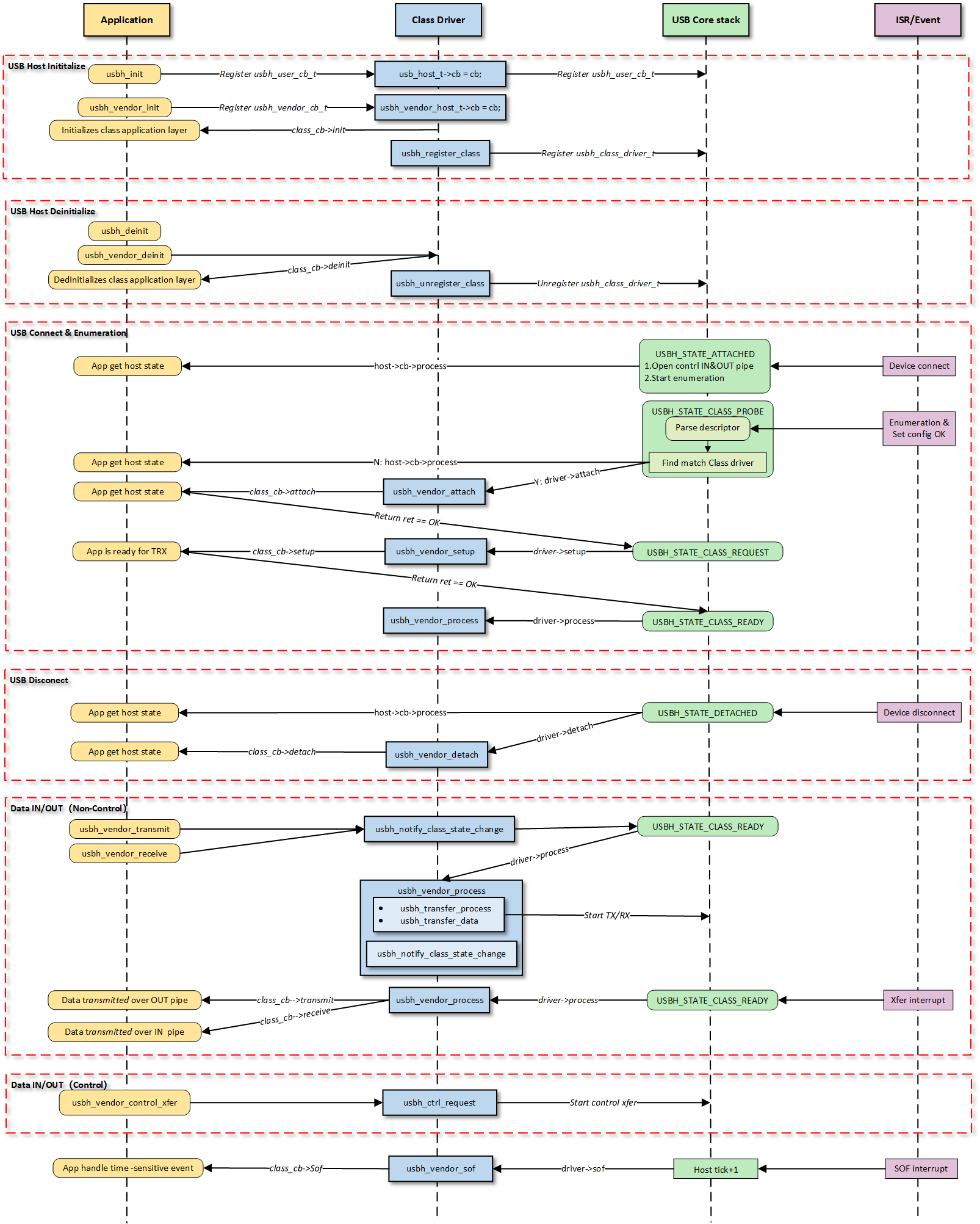
Note
The figure above illustrates the execution flow of callback functions at different levels and does not list all calling scenarios.
Class Driver Callback Functions
The class driver needs to define a standard usbh_class_driver_t structure.
This serves as a unified entry point registered with the USB Core and is the primary method for the Core layer to notify the Class layer that “an event has occurred.”
id_table: Supported device ID list. The core layer uses this table to match with the inserted device to determine whether to load this driver.
attach: Called after device connection and successful matching.
detach: Called when the device is disconnected.
setup: Called when enumeration is complete and the class request phase begins. Used to send class-specific standard control requests to complete necessary configuration before the device enters the data transfer state.
process: The state machine processing function executed after the class driver is ready.
sof: Called during SOF interrupts. Used to handle logic with strict timing requirements, primarily for isochronous transfers.
completed: Called when a transfer on a pipe completes.
Application Layer Callback Functions
The Vendor class driver application layer callback structure usbh_vendor_cb_t is implemented by the user layer. Generally, the following APIs can be implemented:
API |
Description |
|---|---|
init |
Called during class driver initialization to initialize application-related resources. |
deinit |
Called during class driver de-initialization to release application-related resources. |
attach |
Called when the class driver executes the attach callback to handle device connection events at the application layer. |
detach |
Called when the class driver executes the detach callback to handle device disconnection events at the application layer. |
setup |
Called when the class driver executes the setup callback, indicating that the application layer class driver is ready for data transfer. |
receive |
Called when the class driver receives IN data, used by the application layer to process data reported by the device. |
transmit |
Called when the class driver OUT data transfer completes, used by the application layer to obtain the OUT transfer status. |
Loading and Unloading the Class Driver
usbh_vendor_init() is the top-level function used to load the Vendor Class Driver.
Execute User Callback Initialization: If a user
initcallback is registered, it is called first, giving the upper-layer application an opportunity to execute application-specific initialization logic.Register Class Driver: Calls
usbh_register_class()to register the definedusbh_class_driver_tclass driver instance with the Host Core Driver, making the host ready to respond to enumeration.
Example:
typedef struct {
    usbh_vendor_xfer_t bulk_in_xfer; //BULK IN pipe xfer.
    // Other pipe xfer if exit.
    usbh_vendor_cb_t *cb;           //User callback.
    usb_host_t *host;               //USB host core.
    usbh_vendor_state_t state;      //Class Driver state.
} usbh_vendor_host_t;

/* Define Vendor host */
static usbh_vendor_host_t usbh_vendor_host;
/* Define Vendor Class Driver */
static usbh_class_driver_t usbh_vendor_driver = {
    .id_table = vendor_devs,
    .attach = usbh_vendor_attach,
    .detach = usbh_vendor_detach,
    .setup = usbh_vendor_setup,
    .process = usbh_vendor_process,
    .sof = usbh_vendor_sof,
};

int usbh_vendor_init(usbh_vendor_cb_t *cb)
{
    usbh_vendor_host_t *vendor = &usbh_vendor_host;
    /* 1. Execute User Init Callback */
    if (cb != NULL) {
        vendor->cb = cb;
        if (cb->init != NULL) {
            ret = cb->init();
            if (ret != HAL_OK) {
                RTK_LOGS(TAG, RTK_LOG_ERROR, "User init err %d\n", ret);
                return ret;
            }
        }
    }
    /* 2. Register Class Driver */
    usbh_register_class(&usbh_vendor_driver);
    return HAL_OK;
}
usbh_vendor_deinit() is the top-level function used to unload the Vendor Class Driver.
Execute User Callback Cleanup: If a user
deinitcallback is registered, it is called first to inform the upper-layer application to clean up user-layer private resources or logic.Reset State Machine: Sets the driver state machine status to IDLE.
Release All Pipes and Resources: Force closes all open pipes via
usbh_close_pipe()and cleans up all resources allocated during initialization to prevent memory leaks or pipe occupation.Unregister Class Driver: Calls
usbh_unregister_class()to remove the Vendor driver from the USB Core Stack. After this operation, the device will no longer respond to relevant USB events.
Example:
int usbh_vendor_deinit(void)
{
  usbh_vendor_host_t *vendor = &usbh_vendor_host;

  /* 1. Execute User Deinit Callback */
  if ((vendor->cb != NULL) && (vendor->cb->deinit != NULL)) {
    vendor->cb->deinit();
  }
  /* 2. Set the state of the drive state machine to IDLE. */
  vendor->state = VENDOR_STATE_IDLE;
  /* 3. Close all pipelines */
  usbh_vendor_deinit_all_pipe();
  /* 4. Release all resources */
  usbh_vendor_deinit_all_xfer();
  /*5. Unregister Class Driver */
  usbh_unregister_class(&usbh_vendor_driver);
  return HAL_OK;
}
Connection and Disconnection Handling
The connection and disconnection of devices are automatically detected by the USB Core, which then calls the corresponding callbacks of the class driver for resource management.
Device Connection
When the Core layer enumerates a Vendor device matching the usbh_dev_id_t, the usbh_vendor_attach callback is invoked. The main responsibilities of this phase are:
Obtain and parse the corresponding interface descriptor.
Open the corresponding pipe via
usbh_open_pipe()based on the endpoint descriptor.Initialize the transfer management structure
usbh_vendor_xfer_tcorresponding to each pipe.Call the user
attachcallback to inform the application layer.
Example:
static int usbh_vendor_attach(usb_host_t *host)
{
    usbh_vendor_host_t *vendor = &usbh_vendor_host;
    usbh_itf_data_t *itf_data;
    usbh_dev_id_t dev_id = {0,};
    /* 1. Sets up device identification parameters to match a vendor class interface */
    dev_id.bInterfaceClass = VENDOR_CLASS_CODE;
    dev_id.bInterfaceSubClass = VENDOR_SUBCLASS_CODE;
    dev_id.bInterfaceProtocol = VENDOR_PROTOCOL;
    dev_id.mMatchFlags = USBH_DEV_ID_MATCH_ITF_INFO;  //Core only needs to match interface information (ignore VID/PID)
    /* 2. Search for interfaces that match the dev_id rule in the devices associated with the host */
    itf_data = usbh_get_interface_descriptor(host, &dev_id);

    if (itf_data == NULL) {
       // Match failure: Although the device is connected, there is no driver supporting the Interface
        RTK_LOGS(TAG, RTK_LOG_ERROR, "Get itf desc fail\n");
        return HAL_ERR_PARA;
    } else {
        /* 3. If found, initializes the vendor host with the host pointer and sets the state to transfer */
        vendor->host = host;
        vendor->state = VENDOR_STATE_XFER;

        /* 4. Get data in/out endpoints */
        usbh_vendor_get_endpoints(host, itf_data->itf_desc_array);

        /* 5. Calls the `attach` callback function if it exists */
        if ((vendor->cb != NULL) && (vendor->cb->attach != NULL)) {
            vendor->cb->attach();
        }
        return HAL_OK;
    }
}
Device Disconnection
When the device is unplugged, the usbh_vendor_detach callback is invoked. The main responsibilities of this phase are:
Set the driver state machine status to IDLE.
Call
usbh_close_pipe()to close all opened pipes.Call the user
detachcallback to inform the application layer.
Example:
static int usbh_vendor_detach(usb_host_t *host)
{
    UNUSED(host);
    usbh_vendor_host_t *vendor = &usbh_vendor_host;
    /* 1. Reset the state of the driver state machine to IDLE */
    vendor->state = VENDOR_STATE_IDLE;
    /* 2. Close all pipes in turn */
    usbh_vendor_deinit_all_pipe();
    /* 3. Calls the `detach` callback function if it exist */
    if ((vendor->cb != NULL) && (vendor->cb->detach != NULL)) {
        vendor->cb->detach();
    }

    return HAL_OK;
}
Device and Driver Matching Mechanism
In the USB host driver, the attach callback function collaborates with the usbh_dev_id_t structure to complete the critical process from “generic device connection” to “specific interface binding”.
The matching process is as follows:
Define Matching Rules: By configuring the
usbh_dev_id_tstructure, specify target device characteristics (such as Class Code, Protocol, etc.).Match Flags: Use
mMatchFlagsfor precise control over the matching strategy (e.g., matching only VID/PID, or specific Class/SubClass).Flexibility: Precisely control whether to match the entire device or a specific interface within the device (this is especially important for composite devices).
Developers adapt according to the actual connected Vendor devices.
Search Matching: Inside the
attachcallback, call the core APIusbh_get_interface_descriptor().The USB Core iterates through all interface descriptors of the currently connected device and compares them with the passed
usbh_dev_id_trules. If a match is successful, it returns the pointer to the corresponding interface descriptor.
Class Driver State Machine
The usbh_vendor_process callback function is the core state machine handler for the Vendor Class on the host side. Unlike the passive response on the device side, the host-side driver needs to actively maintain device status.
The USB host class driver uses a state machine to manage data transfer processing, with the driver state updated by API calls and underlying interrupt feedback.
The state machine generally contains three core states:
VENDOR_STATE_IDLE (Idle State): Standby state after system initialization or disconnection, waiting for new transfer requests or event triggers.
VENDOR_STATE_XFER (Data Transfer State): Core data processing state; dispatches and processes corresponding transfer events based on the Pipe Number in the event message.
VENDOR_STATE_ERROR (Error Handling State): Exception handling state; attempts error recovery via standard requests (Clear Feature).
Example:
switch (vendor->state) {
case VENDOR_STATE_IDLE:
    break
case VENDOR_STATE_XFER:
    /* Distribute and process according to the pipe number */
    if (event.msg.pipe_num == vendor->bulk_in_xfer.pipe.pipe_num) {
        usbh_vendor_bulk_process_rx(host);
    } else if (event.msg.pipe_num == vendor->isoc_out_xfer.pipe.pipe_num) {
        usbh_vendor_isoc_process_tx(host);
    }
    /* Deal with other pipe */
    break;
case VENDOR_STATE_ERROR:
    /* Try to recover */
    if (usbh_ctrl_clear_feature(host, 0x00U) == HAL_OK) {
        vendor->state = VENDOR_STATE_IDLE;// Restoration successful, reset to IDLE
    }
    break;
}
Data Transfer Processing
This section provides a detailed introduction to the data transfer processing flow in the Vendor class driver. Host-side transfers are mainly divided into three stages: TRX API -> Process -> Callback:
Initiation of Transfer Request: The application layer proactively initiates OUT (transmit) or IN (receive) transfer requests by calling APIs.
State Machine Management: The driver manages data interaction with the device by maintaining a transfer state machine.
Callback Notification: Notifies the application layer via
usbh_vendor_cb_tcallbacks upon transfer completion or error. This callback mechanism decouples the application layer from the low-level driver, eliminating the need for the application to poll and wait.
Start Transmission: The application layer calls the TX API, such as
usbh_vendor_bulk_transmit().Internal API Implementation:
Sets the transfer buffer and length for the pipe.
Sets the pipe to the transfer state
USBH_EP_XFER_START.Calls
usbh_notify_class_state_change()to notify the core of state changes, which will trigger state machine scheduling.
Core Processing: The
usbh_vendor_processcallback detects the event and dispatches it to the corresponding handler function based on the pipe number.Low-level Scheduling: Calls
usbh_transfer_process()to starts the underlying transfer and processes the transfer results.Completion Notification: Calls the user
transmitcallback function to notify the upper layer of the transmission result.
Start Reception: The application layer calls the RX API, such as
usbh_vendor_bulk_receive().Internal API Implementation:
Sets the transfer buffer and length for the pipe.
Sets the pipe to the transfer state
USBH_EP_XFER_START.Calls
usbh_notify_class_state_change()to notify the core of state changes, which will trigger state machine scheduling.
Core Processing: The
usbh_vendor_processcallback detects the event and dispatches it to the corresponding handler function based on the pipe number.Low-level Scheduling: Calls
usbh_transfer_process()to starts the underlying transfer and processes the transfer results.Completion Notification:
If data is received: Calls
usbh_get_last_transfer_size()gets the actual received length.Calls the user
receivecallback function to pass the data up to the application layer.
Note
BULK IN ZLP Handling
If a zero-length packet is received, the
receivecallback is triggered as well, so the application layer needs to check for and handle the ZLP case.
Note
USB DMA requires the data buffer address to be aligned with the Cache line, so the transmit/receive buffer addresses passed down by the application layer must be address-aligned.
Special Processing Logic
BULK ZLP Handling
In Bulk transfers, if the data length is exactly an integer multiple of the MPS (Maximum Packet Size), the driver automatically flags
trx_zlpto automatically receive/send a ZLP after the data to terminate the transfer.Example:
if ((pipe->xfer_len > 0) && ((pipe->xfer_len % pipe->ep_mps) == 0)
    && (pipe->ep_type == USB_CH_EP_TYPE_BULK)) { //ZLP
    pipe->trx_zlp = 1;
}
Isochronous Transfer and Frame Synchronization
Isochronous transfers are time-sensitive and rely on SOF interrupts to handle timing control for isochronous transfers.
SOF Callback: The
usbh_vendor_sofcallback function is triggered at the beginning of each frame to track the current frame number.- Transmission Scheduling: Ensure that data packets are submitted strictly within the correct (micro)frames at regular intervals.
When the TX processing function determines that there is still transmission to be done, it will set the channel status to
USBH_EP_XFER_WAIT_SOF.Verify the frame interval during the SOF callback, and call
usbh_notify_class_state_change()to trigger the core scheduling for actual data transmission when the conditions are met.
Example:
static int usbh_vendor_sof(usb_host_t *host)
{
    usbh_vendor_host_t *vendor = &usbh_vendor_host;

    /* 1.Obtain the current frame number for ISOC scheduling */
    int cur_frame = usbh_get_current_frame_number(host);

    /* 2. Waiting for the correct SOF interval to start next transfer
        - if cur_frame - last frame_num >= interval, means we should trigger a xfer ASAP.
        - if xfer_state = USBH_EP_XFER_WAIT_SOF, it means that last xfer has been done, so in sof intr, we should check whether the next frame will be the xfer frame
    */
    if ((usbh_get_elapsed_frame_cnt(host, pipe->frame_num) >= pipe->ep_interval) ||
        ((pipe->xfer_state == USBH_EP_XFER_WAIT_SOF) && (cur_frame - out_xfer->cur_frame) % pipe->ep_interval == 0)){
        //3. Set next transfer parameters: e.g. buffer and length

        //4. Start next transfer
        usbh_notify_class_state_change(host, pipe->pipe_num);
    }

    return HAL_OK;
}
Pipe Configuration
During the device enumeration phase (in the usbh_vendor_attach callback function), the Vendor Host Driver parses the configuration descriptor and automatically searches for and requests corresponding transfer resources based on the interface descriptor, establishing complete data and control pipes.
The pipe configuration in this example is as follows:
Quantity |
Description |
|---|---|
2 |
Default Control Transfer 0 |
1 |
Bulk IN Transfer |
1 |
Bulk OUT Transfer |
1 |
Interrupt IN Transfer |
1 |
Interrupt OUT Transfer |
1 |
Isochronous IN Transfer |
1 |
Isochronous OUT Transfer |
API Reference
For detailed function prototypes and usage, please refer to the Driver API
Application Example
Application Design
This section provides a detailed introduction to the complete development process of the Vendor application, covering core aspects such as driver loading, hotplug handling, how to establish transmission, and how to process data. However, the data content transmitted (such as Loopback test data) carries no specific business meaning. Developers can base on this framework:
Define private command set: Replace the test data in the example and implement specific private protocol parsing logic.
Adjust resource allocation: Adjust the FIFO size and buffer size based on the actual business throughput.
Driver Initialization
Before using the Vendor driver, configuration structures must be defined and callback functions registered. Subsequently, initialization interfaces are called to load the USB core driver and the Vendor class driver.
Step Description:
Hardware Configuration: Configure USB speed modes (High Speed/Full Speed), interrupt priorities, etc.
Callback Registration: Define the user callback structure
usbh_vendor_cb_tandusbh_user_cb_tmount processing functions for various stages.Core Initialization: Call
usbh_init()to initialize the USB core driver.Class Driver Initialization: Call
usbh_vendor_init()to initialize the Vendor class driver.
Example:
static usbh_config_t usbh_cfg = {
  .speed = USB_SPEED_HIGH,
  .ext_intr_enable = USBH_SOF_INTR,
  .isr_priority = INT_PRI_MIDDLE,
  .main_task_priority = 3U,
  .tick_source = USBH_SOF_TICK,
};

static usbh_vendor_cb_t vendor_usr_cb = {
  .attach = vendor_cb_attach,
  .detach = vendor_cb_detach,
  .setup = vendor_cb_setup,
  .transmit = vendor_cb_transmit,
  .receive  = vendor_cb_receive,
};

static usbh_user_cb_t usbh_usr_cb = {
  .process = vendor_cb_process
};

int ret = 0;

/* Initialize USB host core driver with configuration. */
ret = usbh_init(&usbh_cfg, &usbh_usr_cb);
if (ret != HAL_OK) {
  return;
}

/* Initialize class driver with application callback handler. */
ret = usbh_vendor_init(&vendor_usr_cb);
if (ret != HAL_OK) {
  /* If class driver init fails, clean up the core driver */
  usbh_deinit();
  return;
}
Hot-Plug Event Handling
As a host, the system must robustly handle the dynamic insertion and removal of USB devices. The SDK supports the hotplug mechanism by default.
Processing Logic:
Attach: The USB core detects the device and re-executes the enumeration and driver loading process.
Detach: Triggers a callback to release semaphores. The application thread captures this to execute de-initialization and free heap memory.
Example:
static rtos_sema_t vendor_detach_sema;

/* USB detach callback */
static usbh_vendor_cb_t vendor_usr_cb = {
  .detach = vendor_cb_detach,
};

/* Callback executed in ISR context */
static int vendor_cb_detach(void)
{
  RTK_LOGS(TAG, RTK_LOG_INFO, "DETACH\n");
  rtos_sema_give(vendor_detach_sema);
  return HAL_OK;
}

/* Thread handling the state machine */
static void vendor_hotplug_thread(void *param)
{
  int ret = 0;

  UNUSED(param);

  for (;;) {
    if (rtos_sema_take(vendor_detach_sema, RTOS_SEMA_MAX_COUNT) == RTK_SUCCESS) {
      rtos_time_delay_ms(100);//make sure disconnect handle finish before deinit.

      /* 1. Clean up resources */
      usbh_vendor_deinit();
      /* 2. De-initialize USB core */
      usbh_deinit();

      rtos_time_delay_ms(10);

      RTK_LOGS(TAG, RTK_LOG_INFO, "Free heap: 0x%08x\n", rtos_mem_get_free_heap_size());
      /* 3. Re-initialize for next connection */
      ret = usbh_init(&usbh_cfg, &usbh_usr_cb);
      if (ret != HAL_OK) {
        RTK_LOGS(TAG, RTK_LOG_ERROR, "Init USBH fail: %d\n", ret);
        break;
      }

      ret = usbh_vendor_init(&vendor_usr_cb);
      if (ret != HAL_OK) {
        RTK_LOGS(TAG, RTK_LOG_ERROR, "Init vendor fail: %d\n", ret);
        usbh_deinit();
        break;
      }
    }
  }

  rtos_task_delete(NULL);
}
Data Transfer Processing
Once the Vendor host enumeration is successful, APIs can be called to start data transfer. The following process applies to BULK, INTR, and ISOC transfer. BULK transfer is used as an example here.
static __IO int vendor_is_ready = 0;
static rtos_sema_t vendor_bulk_send_sema;
static rtos_sema_t vendor_bulk_receive_sema;
static u8 vendor_bulk_loopback_tx_buf[USBH_VENDOR_BULK_LOOPBACK_BUF_SIZE] __attribute__((aligned(CACHE_LINE_SIZE)));
static u8 vendor_bulk_loopback_rx_buf[USBH_VENDOR_BULK_LOOPBACK_BUF_SIZE] __attribute__((aligned(CACHE_LINE_SIZE)));

static usbh_vendor_cb_t vendor_usr_cb = {
   .setup = vendor_cb_setup,
   .transmit = vendor_cb_transmit,
   .receive  = vendor_cb_receive,
};

static int vendor_cb_setup(void)
{
   vendor_is_ready = 1;
   return HAL_OK;
}

/**
* @brief USB Vendor transmit callback function
* @param ep_type transmission type (BULK, INTERRUPT, ISOC)
* @return HAL status
*/
static int vendor_cb_transmit(u8 ep_type)
{
   //Release the different semaphore according to different transmission, e.g. transmission type
   switch (ep_type) {
   case USB_CH_EP_TYPE_BULK:
      rtos_sema_give(vendor_bulk_send_sema);
      break;
      //Other transmission
   default:
      break;
   }

   return HAL_OK;
}

/**
* @brief USB Vendor receive callback function
* @param ep_type transmission type (BULK, INTERRUPT, ISOC)
* @param buf Received data buffer
* @param len Length of received data
* @param status Transfer status
* @return HAL status
*/
static int vendor_cb_receive(u8 ep_type, u8 *buf, u32 len, int status)
{
   // Get endpoint maximum packet size for each type
   u16 vendor_bulk_in_mps = usbh_vendor_get_bulk_ep_mps();

   switch (ep_type) {
   case USB_CH_EP_TYPE_BULK:
         // 1. Check if transfer transfer is complete successfully
         // 2. Reset total length and signal completion
         rtos_sema_give(vendor_bulk_receive_sema);
      } else {
         RTK_LOGS(TAG, RTK_LOG_ERROR, "%d RX fail: %d\n", ep_type, status);
      }

      break;
   }
   return HAL_OK;
}

/*---------------- BULK TRX Test --------------------*/

/*1. Wait for device to be ready for data transfer*/
while (1) {
   if (vendor_is_ready) { /* Check if device is ready */
      rtos_time_delay_ms(10);
      break;
   }
}

/* 2. BULK TX test */
/* Initiate transfer with TX configuration: transfer length and times */
usbh_vendor_bulk_transmit(vendor_bulk_loopback_tx_buf, USBH_VENDOR_BULK_LOOPBACK_BUF_SIZE, USBH_VENDOR_BULK_LOOPBACK_CNT);

/* 3. Wait for transfer completion semaphore */
if (rtos_sema_take(vendor_bulk_send_sema, RTOS_SEMA_MAX_COUNT) == RTK_SUCCESS) {
   // Success indicates transfer completion
}

/* 4. BULK RX test */
/* Initiate transfer with RX configuration: transfer length and times */
usbh_vendor_bulk_receive(vendor_bulk_loopback_rx_buf, USBH_VENDOR_BULK_LOOPBACK_BUF_SIZE, USBH_VENDOR_BULK_LOOPBACK_CNT);

/* 5. Wait for transfer completion semaphore */
if (rtos_sema_take(vendor_bulk_receive_sema, RTOS_SEMA_MAX_COUNT) == RTK_SUCCESS) {
   // Success indicates transfer completion
}
The handling methods in the receive callback differ for the three transfer types upon successful reception:
Processing Logic:
Data received via bulk transfer is accumulated until specific conditions are met before releasing the semaphore. This is primarily because the protocol mandates that when a bulk transfer length is a multiple of the MPS (Max Packet Size), a Zero Length Packet (ZLP) must be appended to mark the end of the transfer. The user layer needs to distinguish this situation, so it waits for a complete packet sequence or specific termination conditions (such as a ZLP, a short packet, or a full buffer) to confirm the completion of a full transfer. This mechanism ensures data integrity and correctness, preventing subsequent processing before data is fully received.
Example:
static int vendor_cb_receive(u8 ep_type, u8 *buf, u32 len, int status)
{
   /* 1. Get endpoint maximum packet size of BULK IN endpoint */
   u16 vendor_bulk_in_mps = usbh_vendor_get_bulk_ep_mps();

   switch (ep_type) {
   case USB_CH_EP_TYPE_BULK:
      /* 2. Check if transfer was successful */
      if (status == HAL_OK) {
         /* 3 Update total received length */
         vendor_bulk_total_rx_len += len;

         /* 4. Determine if transfer is complete based on: Zero-length packet (ZLP)/Short packet (not multiple of MPS)/ Buffer full condition */
         if ((len == 0) || (len % vendor_bulk_in_mps)
            || ((len % vendor_bulk_in_mps == 0) && (len < USBH_VENDOR_BULK_LOOPBACK_BUF_SIZE))
            || (vendor_bulk_total_rx_len > USBH_VENDOR_BULK_LOOPBACK_BUF_SIZE)) {
             /* 5. Reset total length and signal completion */
            vendor_bulk_total_rx_len = 0;
            rtos_sema_give(vendor_bulk_receive_sema);
         }
      } else {
         RTK_LOGS(TAG, RTK_LOG_ERROR, "%d RX fail: %d\n", ep_type, status);
      }
      break;
   }
   return HAL_OK;
}
Processing Logic:
Handling interrupt transfers is relatively simple, primarily based on short packet detection. When the received data length is less than or equal to the MPS, it usually indicates the end of a complete transfer cycle. This design aligns with the characteristics of interrupt transfers—small data volume and periodicity—allowing timely identification of transfer completion.
Example:
static int vendor_cb_receive(u8 ep_type, u8 *buf, u32 len, int status)
{
   /* 1. Get endpoint maximum packet size of Interrupt IN endpoint */
   u16 vendor_intr_in_mps = usbh_vendor_get_intr_ep_mps();

   switch (ep_type) {
   case USB_CH_EP_TYPE_INTR:
      /* 2. Check if transfer was successful */
      if (status == HAL_OK) {
          /* 3. Update total received length */
         vendor_intr_total_rx_len += len;

         /* 4. Determine if transfer is complete based on: Short packet (less than MPS) with data received  */
         if (((len < vendor_intr_in_mps) && (vendor_intr_total_rx_len > 0))
            || (vendor_intr_total_rx_len >= USBH_VENDOR_INTR_LOOPBACK_BUF_SIZE)) { //
            /*5. Reset total length and signal completion */
            vendor_intr_total_rx_len = 0;
            rtos_sema_give(vendor_intr_receive_sema);
         }
      } else {
         // Log error if transfer failed
         RTK_LOGS(TAG, RTK_LOG_ERROR, "%d RX fail: %d\n", ep_type, status);
      }
      break;
   }
   return HAL_OK;
}
Processing Logic:
Isochronous transfers use an immediate semaphore release mechanism. Since isochronous transfers are typically used for real-time data transfer (e.g., audio or video streams), timeliness is more critical than data integrity. The upper layer is notified immediately upon receiving each data packet to ensure real-time requirements are met.
Example:
static int vendor_cb_receive(u8 ep_type, u8 *buf, u32 len, int status)
{
   switch (ep_type) {
   case USB_CH_EP_TYPE_ISOC:
      // For isochronous transfers, immediately signal completion
      rtos_sema_give(vendor_isoc_rxdone_sema);
      break;
   }
   return HAL_OK;
}
Note
Buffers allocated for transfer and reception must be Cache-line aligned.
For the complete data transfer logic, please refer to the SDK example code:
{SDK}/component/example/usb/usbh_vendor/example_usbh_vendor.c.
Driver Deinitialization
When USB functionality is no longer needed or the system is shutting down, release resources in the reverse order of loading.
Example:
/* Deinitialize Vendor class driver. */
usbd_vendor_deinit();

/* Deinitialize USB host core driver. */
usbd_deinit();
Operation method
The example code path is: {SDK}/component/example/usb/usbh_vendor. It provides provides a complete reference solution for developers to design custom vendor products.
This section introduces a complete Vendor host loopback example, demonstrating how to implement custom bidirectional data communication with the device via the Vendor protocol stack.
Configuration and Compilation
Menuconfig Configuration
In the
amebaxxx_gcc_projectdirectory, type./menuconfig.py, follow the steps below to selectUSBH VENDOR, then save and exit.- Choose `CONFIG USB --->`: [*] Enable USB USB Mode (host) ---> [*] VendorCompilation and Flashing
Compile according to the instructions below, and flash the
imagefile to the development board.cd amebaxxx_gcc_project ./build.py -a usbh_vendor
Verification
Host Startup
Reset the development board and observe the serial log; it should display the following startup message:
[VND-I] USBH vendor demo start
Connect to device
Connect the vendor-specific USB device (e.g. another Ameba board running usbd_vendor application) to the USB port of the board with USB cable.
Data communication test
The Ameba development board will identify the vendor device and perform transceiving tests.
```
[VND-I] ISOC test start, times:100, size: 1024
[VEN-I] ISOC OUT test finish 100/100:
[VEN-I]   0   1   2   3   4   5   6   7   8   9

```
[VEN-I]  90  91  92  93  94  95  96  97  98  99
[VEN-I] ISOC IN test finish 100/100:
[VEN-I]   0   1   2   3   4   5   6   7   8   9

```
[VEN-I]  90  91  92  93  94  95  96  97  98  99
[VND-I] ISOC test PASS
[VND-I] BULK loopback test start, times:100, size: 512
[VND-I] INTR loopback test start, times:100, size: 1024
[VND-I] BULK loopback test PASS 100/100
[VND-I] INTR loopback test PASS 100/100
[VND-I] USBH vendor demo stop