The USB CDC ACM (Communication Device Class - Abstract Control Model) protocol employs the USB Bulk Transfer mechanism to provide a generic high-speed data pass-through channel, suitable for real-time transmission of high-throughput data streams and command interaction.
Ameba implements CDC ACM functionality in compliance with USB-IF standards, establishing a bidirectional transparent data transmission link. The Host can exchange raw data directly with Ameba’s internal logic or backend peripherals via the standard USB interface, effectively masking and abstracting the underlying transmission details.
Functioning as a USB data pass-through bridge, Ameba establishes a high-speed data link between the master device (Host, such as a PC or embedded host) and the external world via the USB interface. By combining this with other peripheral interfaces, it enables several typical applications:
Sensor Acquisition and Robot Control: Ameba acts as a high-performance sensor node, collecting high-speed environmental or motion data from the front end. This data is uploaded in real-time to the robot control system via the USB channel, supporting zero-packet-loss transmission of high-frequency raw data and rapid dispatch of closed-loop control commands.
Device Management and Firmware Maintenance: Geared towards the lifecycle management of IoT devices, management terminals can establish communication with the device via the CDC channel. This facilitates parameter configuration, operational status diagnostics, and supports firmware upgrades (OTA) and maintenance through this data link.
Wireless Data Gateway: Leveraging its integrated Wi-Fi and Bluetooth modules, Ameba serves as a wireless bridge. It transparently forwards data streams received from the Host via USB to the wireless network, providing plug-and-play wireless access capabilities for industrial control hosts or management terminals that lack native wireless functionality.
CDC (Communication Device Class) is a standard for general communication devices defined by the USB specification. Within its PSTN (Public Switched Telephone Network) subclass, the most commonly used is ACM (Abstract Control Model). It defines a standardized set of commands for controlling communication parameters, such as:
Set baud rate (such as 9600, 115200)
Configure data bits, stop bits, and parity bits
Control DTR/RTS and other line status signals
It is through ACM that a USB CDC device can be recognized by the host as a standard “virtual serial port”.
The USB-IF has officially released the CDC (Class Driver Control) basic protocol and PSTN (Public Switched Telephone Network) sub-class specifications. During the development process, please refer to the following core documents:
Specification type
Document
CDC 1.2 (Communication Device Class Basic Protocol)
The CDC ACM architecture utilizes a dual-interface mechanism to separate control flow from data flow, and logically binds them into a single functional unit via the Union Functional Descriptor.
Communication Class Interface (CCI)
Responsible for device management control and signaling interaction.
Control transmission: Transmit specific requests through the default control endpoint.
The host primarily sends PSTN control commands, with core instructions including SetLineCoding for configuring baud rate/data bits, and SetControlLineState for controlling RTS/DTR handshake signals.
Interrupt transmission: Utilizing interrupt input endpoints to achieve asynchronous status notification from the device to the host.
A typical application is to report changes in hardware signal status such as DCD, DSR, or Ring in real-time through SERIAL_STATE.
Data Class Interface (DCI)
Responsible for carrying application-layer payload data streams. This interface is typically configured as a pair of bulk endpoints (Bulk IN/Bulk OUT), serving solely as a transparent data transmission channel without involving the parsing or processing of control commands.
In addition to adhering to standard USB descriptors (such as device descriptor, configuration descriptor, and endpoint descriptor), CDC ACM devices also define Class-Specific Functional Descriptors to specify the capabilities of the abstract control model.
CDC ACM Descriptor Topology
The following example illustrates the descriptor topology using a High Speed configuration.
Device Descriptor
└── Identifies basic device information (Class: 0x02 CDC, SubClass: 0x02 ACM)

Configuration Descriptor
├── Includes total length, power attributes (Self-powered), etc.
│
├── Communication Class Interface Descriptor (Interface 0)
│   ├── Standard Interface Descriptor (Class: 0x02, SubClass: 0x02, Protocol: 0x01 AT Commands)
│   │
│   ├── Class-Specific Functional Descriptors (Defines ACM capabilities)
│   │   ├── Header Functional Descriptor (Declares CDC Spec version)
│   │   ├── Call Management Functional Descriptor (Call handling capabilities)
│   │   ├── ACM Functional Descriptor (Line coding & state capabilities)
│   │   └── Union Functional Descriptor (Binds Interface 0 and Interface 1)
│   │
│   └── Standard Endpoint Descriptor (Interrupt IN)
│       └── Used for Serial State notifications
│
├── Data Class Interface Descriptor (Interface 1)
│   ├── Standard Interface Descriptor (Class: 0x0A Data, SubClass: 0x00, Protocol: 0x00)
│   │
│   ├── Standard Endpoint Descriptor (Bulk OUT)
│   │   └── Host -> Device Data Stream
│   │
│   └── Standard Endpoint Descriptor (Bulk IN)
│       └── Device -> Host Data Stream
│
├── Device Qualifier Descriptor
│   └── Device information for other speed modes
│
└── Other Speed Configuration Descriptor
    └── Configuration information for Full Speed mode
Functional Descriptor
In the communication interface, the CDC must include the following special “function descriptor” header:
Header Functional Descriptor: Indicates the CDC version.
Call Management Functional Descriptor: Indicates how the device handles call management.
Abstract Control Management Functional Descriptor: Indicates which commands (such as Set_Line_Coding) are supported.
Union Functional Descriptor: specifies which one is the Master interface and which one is the Slave interface.
Header Functional Descriptor
Header Functional Descriptor
├── bLength            : 1 byte   → Total descriptor length (Fixed = 5 bytes)
├── bDescriptorType    : 1 byte   → 0x24 (CS_INTERFACE: Class-Specific Interface)
├── bDescriptorSubtype : 1 byte   → 0x00 (HEADER)
└── bcdCDC             : 2 bytes  → USB Class Definitions for Communication Devices Specification Release Number
                                    • 0x0110 = Release 1.10 (Common for ACM)
Call Management Functional Descriptor
Call Management Functional Descriptor
├── bLength            : 1 byte   → Total descriptor length (Fixed = 5 bytes)
├── bDescriptorType    : 1 byte   → 0x24 (CS_INTERFACE)
├── bDescriptorSubtype : 1 byte   → 0x01 (CALL_MANAGEMENT)
├── bmCapabilities     : 1 byte   → The capabilities that this configuration supports:
│                                   • Bit 0 = 0: Device does not handle call management itself
│                                   • Bit 0 = 1: Device handles call management itself
│                                   • Bit 1 = 0: Call management commands does not sent over Data Class Interface
│                                   • Bit 1 = 1: Call management commands can be sent over Data Class Interface
│                                   • Bits 2-7: Reserved (Reset to zero)
└── bDataInterface     : 1 byte   → Interface number of Data Class interface optionally used for call management
                                    (Zero if no data interface is used)
ACM Functional Descriptor
Abstract Control Management (ACM) Functional Descriptor
├── bLength            : 1 byte   → Total descriptor length (Fixed = 4 bytes)
├── bDescriptorType    : 1 byte   → 0x24 (CS_INTERFACE)
├── bDescriptorSubtype : 1 byte   → 0x02 (ABSTRACT_CONTROL_MANAGEMENT)
└── bmCapabilities     : 1 byte   → The capabilities that this configuration supports:
                                    • Bit 0: Comm_Feature (Supports Set_Comm_Feature, Clear_Comm_Feature, Get_Comm_Feature)
                                    • Bit 1: Line_Coding (Supports Set_Line_Coding, Set_Control_Line_State, Get_Line_Coding, Serial_State)
                                    • Bit 2: Send_Break (Supports Send_Break)
                                    • Bit 3: Network_Connection (Supports Network_Connection)
                                    • Bits 4-7: Reserved (Reset to zero)
Union Functional Descriptor
Union Functional Descriptor
├── bLength            : 1 byte   → Total descriptor length (3 + Number of slave interfaces)
├── bDescriptorType    : 1 byte   → 0x24 (CS_INTERFACE)
├── bDescriptorSubtype : 1 byte   → 0x06 (UNION)
├── bMasterInterface   : 1 byte   → The interface number of the Communication or Data Class interface
│                                   (Designated as the controlling interface for the union)
└── bSlaveInterface0   : 1 byte   → Interface number of the first subordinate interface in the union
│    ⋮
└── bSlaveInterface(N) : 1 byte   → Interface number of the last subordinate interface in the union
Note
For specifications regarding the CDC ACM transfer protocol, please refer to USB CDC ACM Specification 。
Control requests for CDC ACM devices are categorized into Standard Requests and Class-Specific Requests.
This section primarily introduces the class-specific requests unique to CDC ACM and utilized for implementing core functionalities such as serial port parameter configuration and flow control signal management for virtual serial ports.
Request Name
Requirement
Description
SEND_ENCAPSULATED_COMMAND
Required
The host sends an encapsulated command to the device.
The data format must adhere to the control protocol
supported by the device (e.g., AT command set).
GET_ENCAPSULATED_RESPONSE
Required
The host retrieves response data for an encapsulated
command from the device. The response format adheres
to the protocol supported by the device.
SET_COMM_FEATURE
Optional
Sets the status of a specific communication feature.
The target feature is specified by a feature selector.
GET_COMM_FEATURE
Optional
Queries the current setting status of a specific
communication feature.
CLEAR_COMM_FEATURE
Optional
Clears the setting of a specific communication feature,
resetting it to the default state.
SET_LINE_CODING
Optional (+)
The host configures line coding properties for async
serial communication (e.g., baud rate, stop bits,
parity, data bits).
GET_LINE_CODING
Optional (+)
The host queries the currently configured line coding
properties for asynchronous serial communication.
SET_CONTROL_LINE_STATE
Optional
The host controls the state of RS-232/V.24 standard
control signals (e.g., DTR and RTS signal levels).
SEND_BREAK
Optional
The host requests the device to generate a “Break”
signal of a specific duration on the transmission
end, simulating an RS-232 style line break.
Note
The above requests all belong to Communications Class specific requests.
For Analog Modem applications, although the specification lists requests marked with (+) as optional, it is strongly recommended to implement these requests to ensure compatibility.
This section presents the CDC ACM class-specific descriptor structures defined at the driver layer. These structures correspond to the standard descriptor definitions within the USB protocol specification.
Device Descriptor
└─ USB Version 2.00 (CDC ACM)

Configuration Descriptor (Interfaces 2)
│
├─ Communication Interface (IF 0, CCI)
│  ├─ Header Functional (CDC 1.10)
│  ├─ Call Management Functional (Data IF=1, Handled by Host)
│  ├─ ACM Functional (Cap=0x02: Line Coding & Serial State)
│  ├─ Union Functional (Master=0, Slave=1)
│  └─ Endpoint: INTR IN, maxpkt=HS_INTR_SIZE, Interval=HS_Interval
│
└─ Data Interface (IF 1, DCI)
   ├─ Endpoint: BULK OUT, maxpkt=0x0200 (512 bytes)
   └─ Endpoint: BULK IN,  maxpkt=0x0200 (512 bytes)

Device Qualifier Descriptor
└─ USB 2.0

Other Speed Configuration Descriptor (Interfaces 2)
│
├─ Communication Interface (IF 0, CCI)
│  ├─ Header Functional (CDC 1.10)
│  ├─ Call Management Functional (Data IF=1, Handled by Host)
│  ├─ ACM Functional (Cap=0x02: Line Coding & Serial State)
│  ├─ Union Functional (Master=0, Slave=1)
│  └─ Endpoint: INTR IN, maxpkt=FS_INTR_SIZE, Interval=FS_Interval
│
└─ Data Interface (IF 1, DCI)
   ├─ Endpoint: BULK OUT, maxpkt=0x0040 (64 bytes)
   └─ Endpoint: BULK IN,  maxpkt=0x0040 (64 bytes)
The driver implements the core Class-Specific Requests defined by the CDC ACM specification, primarily including:
SET_LINE_CODING
GET_LINE_CODING
SET_CONTROL_LINE_STATE
Note
Developers may refer to the existing implementation to extend other types of requests. The CDC ACM driver source code is located at: {SDK}/component/usb/device/cdc_acm
This section outlines the complete usage workflow of the CDC ACM driver, covering core aspects such as initialization, hot-plug management, data echo processing, and virtual serial port parameter configuration.
Define the configuration structure and register callback functions, then invoke the initialization interface to load the USB device core and the CDC ACM class driver.
// Do not change the settings unless indeed necessary#define CONFIG_CDC_ACM_BULK_IN_XFER_SIZE 2048U#define CONFIG_CDC_ACM_BULK_OUT_XFER_SIZE 2048Ustaticusbd_config_tcdc_acm_cfg={.speed=CONFIG_USBD_CDC_ACM_SPEED,.isr_priority=INT_PRI_MIDDLE,.intr_use_ptx_fifo=0U,};staticusbd_cdc_acm_cb_tcdc_acm_cb={.init=cdc_acm_cb_init,/* USB init callback */.deinit=cdc_acm_cb_deinit,/* USB deinit callback */.setup=cdc_acm_cb_setup,/* USB setup callback */.received=cdc_acm_cb_received,/* USB received callback */.status_changed=cdc_acm_cb_status_changed,/* USB status change callback */};intret=0;/** * Initialize USB device core driver with configuration. * param[in] cfg: USB device configuration. * return 0 on success, non-zero on failure. */ret=usbd_init(&cdc_acm_cfg);if(ret!=HAL_OK){return;}/** * Initializes class driver with application callback handler. * param[in] bulk_out_xfer_size: BULK OUT xfer buffer malloc length. * param[in] bulk_in_xfer_size: BULK IN xfer buffer malloc length. * param[in] cb: Pointer to the user-defined callback structure. * return 0 on success, non-zero on failure. */ret=usbd_cdc_acm_init(CONFIG_CDC_ACM_BULK_OUT_XFER_SIZE,CONFIG_CDC_ACM_BULK_IN_XFER_SIZE,&cdc_acm_cb);if(ret!=HAL_OK){/** * Deinitialize USB device core driver. * return 0 on success, non-zero on failure. */usbd_deinit();return;}
Monitor USB connection status changes (connection/disconnection) by registering the status_changed callback function. It is recommended to use a semaphore to notify a dedicated task thread for processing, thereby avoiding the execution of time-consuming operations within the interrupt context.
/* USB status change callback */staticusbd_cdc_acm_cb_tcdc_acm_cb={.status_changed=cdc_acm_cb_status_changed};/* Callback executed in ISR context */staticvoidcdc_acm_cb_status_changed(u8old_status,u8status){RTK_LOGS(TAG,RTK_LOG_INFO,"Status change: %d -> %d \n",old_status,status);cdc_acm_attach_status=status;rtos_sema_give(cdc_acm_attach_status_changed_sema);}/* Thread handling the state machine */staticvoidcdc_acm_hotplug_thread(void*param){intret=0;UNUSED(param);for(;;){if(rtos_sema_take(cdc_acm_attach_status_changed_sema,RTOS_SEMA_MAX_COUNT)==RTK_SUCCESS){if(cdc_acm_attach_status==USBD_ATTACH_STATUS_DETACHED){RTK_LOGS(TAG,RTK_LOG_INFO,"DETACHED\n");/* Clean up resources */usbd_cdc_acm_deinit();ret=usbd_deinit();if(ret!=0){break;}/* Re-initialize for next connection */ret=usbd_init(&cdc_acm_cfg);if(ret!=0){break;}ret=usbd_cdc_acm_init(CONFIG_CDC_ACM_BULK_OUT_XFER_SIZE,CONFIG_CDC_ACM_BULK_IN_XFER_SIZE,&cdc_acm_cb);if(ret!=0){usbd_deinit();break;}}elseif(cdc_acm_attach_status==USBD_ATTACH_STATUS_ATTACHED){RTK_LOGS(TAG,RTK_LOG_INFO,"ATTACHED\n");}else{RTK_LOGS(TAG,RTK_LOG_INFO,"INIT\n");}}}RTK_LOGS(TAG,RTK_LOG_INFO,"Hotplug thread fail\n");rtos_task_delete(NULL);}
Upon successful enumeration of CDC ACM, the Host sends data via the virtual serial port. The driver supports both synchronous and asynchronous data processing modes, controlled by the macro CONFIG_USBD_CDC_ACM_ASYNC_XFER.
Data Reception Callback
All data from the Host is passed in via the cdc_acm_cb_received callback function.
Synchronous Echo (Sync Echo)
If asynchronous transfer is not enabled, usbd_cdc_acm_transmit() is called directly within the reception callback to echo the received data back to the Host.
Asynchronous Transfer (Async Transfer)
If asynchronous transfer is enabled, received data is stored in the cdc_acm_async_xfer_buf ring buffer, and the transmission thread cdc_acm_xfer_thread is woken up via a semaphore. This thread is responsible for sending data in packets to avoid time-consuming operations or blocking within the interrupt context.
/* In callback: Echo immediately */staticintcdc_acm_cb_received(u8*buf,u32len){/* Directly transmit received data back to host */returnusbd_cdc_acm_transmit(buf,len);}
/* In callback: Buffer data & Trigger Task */staticintcdc_acm_cb_received(u8*buf,u32len){// 1. Check if transfer is currently busyif(cdc_acm_async_xfer_busy){returnHAL_BUSY;}// 2. Copy data to internal buffer// (Logic for buffer overflow check omitted...)memcpy(...,buf,len);// 3. If buffer full, signal the transfer threadif(buffer_is_full){rtos_sema_give(cdc_acm_async_xfer_sema);}returnHAL_OK;}/* In task thread: Handle Transmission */staticvoidcdc_acm_xfer_thread(void*param){for(;;){// 1. Wait for signal from callbackif(rtos_sema_take(cdc_acm_async_xfer_sema,RTOS_SEMA_MAX_COUNT)==RTK_SUCCESS){cdc_acm_async_xfer_busy=1;// Set busy flag// 2. Loop until all buffered data is sentwhile(data_remaining>0){// Try to transmit a chunk (Bulk size)ret=usbd_cdc_acm_transmit(xfer_buf,chunk_size);if(ret==HAL_OK){// Advance buffer pointer......}else{// 3. If HW is busy, retry after delayrtos_time_delay_us(200);}}// 4. Transmission complete, clear flagcdc_acm_async_xfer_busy=0;}}}
Note
For the complete data transmission and reception logic, please refer to the SDK example code: {SDK}/component/example/usb/usbd_cdc_acm/example_usbd_cdc_acm.c.
This section introduces a complete USB CDC ACM (Virtual COM Port) echo example, demonstrating how to implement bidirectional character communication between a PC and the development board using the CDC ACM protocol stack.
The example code path is: {SDK}/component/example/usb/usbd_cdc_acm. It can serve as a baseline reference for USB-to-Serial pass-through or Command Line Interface (CLI) implementation.
Reboot the development board and observe the serial log; the following startup information should be displayed:
[ACM-I] USBD CDC ACM demo start
Connect to Host
Connect the development board to a PC (e.g., Windows computer) using a USB cable.
Serial Communication Test
Launch any serial debugging tool (e.g., Tera Term or Realtek Trace Tool) and open the virtual serial port corresponding to the Ameba development board’s USB port.
Attempt to send any character message to the development board. Observe the terminal interface; the development board should echo the received message back to the Host exactly as received.
Note
For Windows 7/XP Host users, the system may not automatically install the driver. Please manually install the CDC ACM driver file RtkUsbCdcAcmSetup.INF.
Before installation, ensure that the INF file contains the VID/PID values used by the current CDC ACM class, such as:
[DeviceList]%DESCRIPTION%=DriverInstall, USB\VID_0BDA&PID_8720%DESCRIPTION%=DriverInstall, USB\VID_0BDA&PID_8721%DESCRIPTION%=DriverInstall, USB\VID_0BDA&PID_8722%DESCRIPTION%=DriverInstall, USB\VID_0BDA&PID_8730%DESCRIPTION%=DriverInstall, USB\VID_0BDA&PID_8006%DESCRIPTION%=DriverInstall, USB\VID_0BDA&PID_8061; Add support for new VID/PID
The USB Human Interface Device (HID) protocol is a standard interface specification defined by USB-IF for connecting human-computer interaction devices (such as keyboards, mice, game controllers, touchscreens, etc.).
The Ameba platform, based on the official USB-IF standards, implements a fully functional USB HID device-side protocol stack. This solution provides the system with a stable, low-latency human-computer interaction interface and supports highly flexible custom configurations.
Simulate basic keyboard key presses and mouse movement events
Unidirectional/Bidirectional Communication Support:
Mouse: Supports unidirectional reporting of HID data (Input Report).
Keyboard: Supports bidirectional HID data communication (Input & Output Report), capable of handling host-sent LED status controls (e.g., “Caps Lock” indicator).
Supports configuring parameters such as speed mode
As a USB HID device, Ameba can send standard input reports to a host (such as a PC, tablet, or smart TV) via a USB interface. Leveraging its built-in Wi-Fi and Bluetooth® capabilities, Ameba enables various innovative cross-protocol, cross-medium applications. For example,
Wireless Peripheral Adapter (Dongle): Ameba acts as a USB receiver (dongle) plugged into the host. It receives data from remote wireless keyboards/mice via Wi-Fi or Bluetooth, converts it into standard USB HID packets, and transparently transmits them to the host, enabling plug-and-play wireless peripherals.
IoT Smart Control Gateway: Ameba serves as a bridge between physical input and digital control. It reads signals from local physical buttons, knobs, or sensors and maps them to standard input commands via the USB HID protocol or converts them into network control instructions, enabling precise control over smart home and industrial equipment.
Game Controller Adapter: Supports connecting non-standard interface game controllers (such as old console controllers or custom arcade joysticks) to Ameba. The internal protocol stack converts their signals into standard HID game controller reports, ensuring compatibility with PCs or modern gaming consoles.
The HID (Human Interface Device) protocol is a standard interface and data transmission specification defined within the USB specification framework, specifically designed for human-computer interaction devices. This protocol defines the data interaction format and control response mechanism between the host and the device.
Common devices that comply with the HID standard include:
USB-IF has officially released the core HID protocol specification and Usage Tables for defining device functionality. Developers can refer to the following core documents:
The definitions of general HID technical terms used in this document are as follows:
Terms
Description
Report
The basic unit of data transmitted between an HID device and the host. The structure of the data packet is defined by the Report Descriptor.
Usage
An identifier describing the specific meaning of data. For example, defining whether a data bit represents a “left-click” or the “X-axis coordinate”.
Collection
A logical structure that groups related input/output data items. For example, grouping a mouse’s X-axis, Y-axis, and buttons into a “mouse” collection.
Item
The basic building block of a report descriptor, categorized into Main items, Global items, and Local items.
The higher the sampling frequency, the higher quality the sound will be.
The HID protocol stack adopts a layered architecture designed to decouple low-level USB transport details from upper-layer application logic. The system architecture mainly consists of the following core components: the USB core transport driver, the HID class driver, and HID applications for specific types.
Located at the top of the architecture, responsible for handling specific business logic. For example: collecting sensor data and packaging it into mouse coordinate reports, or receiving keyboard LED control commands and driving GPIOs to light the indicators.
HID Class Driver
Implements the Device Class Definition for HID 1.11 specification. Its main responsibilities include: parsing and constructing HID protocol-specific data packets, managing the Report Descriptor, and handling Class-Specific Requests.
USB Core & Transfer Driver
Responsible for handling the standard USB enumeration process, endpoint management, and low-level packet scheduling, shielding the upper layers from differences in hardware controllers.
HID devices achieve low-latency or low-bandwidth interaction through specific Endpoint configurations. In terms of logical functionality, HID interfaces primarily rely on the following two transfer methods:
Control Pipe
Mapped Endpoint: Default control endpoint 0 (Endpoint 0).
Enumeration & Configuration: Transmits standard USB descriptors (Device, Configuration, Interface Descriptors) as well as HID-specific HID Descriptors and Report Descriptors.
Class-Specific Requests: Handles HID protocol control commands, such as Set Idle (set idle rate).
Low-Frequency Data Transfer: When the device is not configured with an Interrupt OUT endpoint, the host sends Output Reports (e.g., setting keyboard “Caps Lock” LED state) via Control Transfer.
Interrupt Pipe
Functional Description: Utilizes USB’s polling mechanism to ensure real-time data transmission.
Interrupt IN: Mandatory. Responsible for real-time transmission of asynchronous data generated by the device (e.g., key press, mouse movement, touchscreen coordinates) to the host.
Interrupt OUT: Optional. Responsible for the host sending low-latency downstream data to the device. Commonly used in scenarios requiring high real-time feedback, such as force feedback vibration commands for gamepads. If this endpoint is not defined, downstream data will fall back to the Control Pipe for transmission.
In addition to adhering to standard USB descriptors, HID devices introduce their own unique descriptor system. The most crucial ones are the HID Descriptor and the Report Descriptor.
HID Descriptor Topology
Device Descriptor
└── Identifies basic device information (USB Version 2.00)

Configuration Descriptor
├── Contains total length of the entire configuration, power supply information, etc.
│
└── Interface Descriptor (Interface 0)
        ├── Standard Interface Descriptor (Interface 0, Human Interface Device)
        ├── HID Descriptor(HID Version, bNumDescriptors, etc)
        │       └── Report Descriptor()
        ├── Endpoint Descriptor(Interrupt In)
        └── Endpoint Descriptor(Interrupt Out)

Device Qualifier Descriptor
└── Device information while running in another speed mode

Other Speed Configuration Descriptor
├── Configuration information while running in another speed mode.
│
└── Interface Descriptor (Interface 0)
        ├── Standard Interface Descriptor (Interface 0, Human Interface Device)
        ├── HID Descriptor(HID Version, bNumDescriptors, etc)
        │       └── Report Descriptor()
        ├── Endpoint Descriptor(Interrupt In)
        └── Endpoint Descriptor(Interrupt Out)
HID Descriptor
Located within the configuration descriptor set, it informs the host about which subordinate descriptors (usually the report descriptor) this interface contains and their lengths.
HID Descriptor
├── bLength            : 1 byte  → Total descriptor length
├── bDescriptorType    : 1 byte  → 0x21 (HID Descriptor)
├── bcdADC             : 2 bytes → HID Version
├── bCountryCode       : 1 byte  → Numeric expression identifying country code of the localized hardware
├── bNumDescriptors    : 1 byte  → Numeric expression specifying the number of class descriptors
│                        └─ (always at least one i.e. Report descriptor.)
├── bDescriptorType    : 1 byte  → Constant name identifying type of class descriptor.
└── wDescriptorLength  : 2 byte  → Numeric expression that is the total size of the Report descriptor.
Report Descriptor
This is a character stream composed of specific Items, not a fixed structure.
It flexibly defines the data format, length, usage, and physical range that the device can generate or receive. The host must parse this descriptor to understand the data sent by the device.
Writing HID Report Descriptors is very flexible and complex. It is recommended to use the HID Descriptor Tool provided by USB-IF for generation and validation.
Control requests for HID devices are divided into Standard Requests and Class-Specific Requests.
This section mainly introduces HID-specific Class-Specific Requests, which are primarily used to manage report status and protocol behavior. The support requirements for different types of devices for these requests are shown in the table below:
Used by the host to control keyboard LED status. The following is a data example for turning on the “Caps Lock” light:
Filed
Length(bits)
Offset(bits)
Value
Num Lock
1
0
0
Caps Lock
1
1
1
Scroll Lock
1
2
0
Compose
1
3
0
Kana
1
4
0
Note
Report ID:
The UAC protocol typically requires the transmitted number of channels to be a power of two (e.g., 2, 4, 8, 16, etc.). If the actual physical channel count (e.g., 10 channels) does not comply with this rule, it must be rounded up to the nearest power of two (configured for transmission as 16 channels). The extra channel positions are filled with invalid data.
This section details the internal implementation specifics of the HID class driver, including the hierarchical structure of descriptors, the support status for class-specific requests, and the endpoint configuration scheme.
The descriptor topology defined within the HID class driver is shown below. These structures strictly adhere to the USB 2.0 protocol specification and HID class definitions.
Device Descriptor
└── Identifies basic device information (USB Version 2.00)

Configuration Descriptor
├── Contains total length of the entire configuration, power supply information, etc.
│
└── Interface Descriptor (Interface 0)
        ├── Standard Interface Descriptor (Interface 0, Human Interface Device)
        ├── HID Descriptor(HID Version, bNumDescriptors, etc)
        │       └── Report Descriptor()
        └── Endpoint Descriptor(Interrupt In)

Device Qualifier Descriptor
└── Device information while running in another speed mode

Other Speed Configuration Descriptor
├── Configuration information while running in another speed mode.
│
└── Interface Descriptor (Interface 0)
        ├── Standard Interface Descriptor (Interface 0, Human Interface Device)
        ├── HID Descriptor(HID Version, bNumDescriptors, etc)
        │       └── Report Descriptor()
        └── Endpoint Descriptor(Interrupt In)
Device Descriptor
└── Identifies basic device information (USB Version 2.00)

Configuration Descriptor
├── Contains total length of the entire configuration, power supply information, etc.
│
└── Interface Descriptor (Interface 0)
        ├── Standard Interface Descriptor (Interface 0, Human Interface Device)
        ├── HID Descriptor(HID Version, bNumDescriptors, etc)
        │       └── Report Descriptor()
        ├── Endpoint Descriptor(Interrupt In)
        └── Endpoint Descriptor(Interrupt Out)

Device Qualifier Descriptor
└── Device information while running in another speed mode

Other Speed Configuration Descriptor
├── Configuration information while running in another speed mode.
│
└── Interface Descriptor (Interface 0)
        ├── Standard Interface Descriptor (Interface 0, Human Interface Device)
        ├── HID Descriptor(HID Version, bNumDescriptors, etc)
        │       └── Report Descriptor()
        ├── Endpoint Descriptor(Interrupt In)
        └── Endpoint Descriptor(Interrupt Out)
This driver stack complies with the USB HID 1.11 specification and has implemented the basic framework for core Class-Specific Requests.
The driver layer has completed the underlying message communication, protocol parsing, and data transmission flow. Developers do not need to focus on USB protocol details; they only need to reference the existing source code architecture and implement specific business logic in the provided interfaces. Source code path: {SDK}/component/usb/device/hid
Class-Specific Request Type
Note
Get Report
The driver has completed the request response flow. Note: The default implementation returns zero data. The specific Report content must be populated at the application layer.
Set Report
The driver has received the data packet. Developers need to implement the specific processing logic for data (Output/Feature Report) sent by the host.
Get Idle
Standard implementation.
Set Idle
Standard implementation.
Get Protocol
Used to query the current protocol mode (Boot/Report).
Set Protocol
The driver has parsed the request. Developers need to perform corresponding state switching based on the protocol mode (Boot or Report) sent by the host.
This section details the complete development process for the HID driver, covering driver initialization, hotplug management, data transmission mechanisms, and resource release.
Define the configuration structure, register callback functions, and then call the initialization interface to load the USB device core and the UAC class driver.
Configuration: Configure USB speed mode and interrupt priority.
Callback Registration: Define the user callback structure usbd_hid_usr_cb_t and mount handler functions for each stage.
Core Initialization: Call usbd_init() to initialize the USB core.
Class Driver Init: Call usbd_hid_init() to initialize the HID class driver.
/* * 1. Configure USB speed (High Speed or Full Speed) and interrupt priority. */staticusbd_config_thid_cfg={.speed=CONFIG_USBD_HID_SPEED,.isr_priority=INT_PRI_MIDDLE,};/* * 2. Define user callbacks for HID events. */staticusbd_hid_usr_cb_thid_usr_cb={.init=hid_cb_init,/* USB init callback */.deinit=hid_cb_deinit,/* USB deinit callback */.setup=hid_cb_setup,/* USB setup callback */.transmitted=hid_cb_transmitted,/* Data transmission complet callback */.received=hid_cb_received,/* Data reception callback */.status_changed=hid_cb_status_changed,/* Connection status change callbac */};intret=0;/** * Initialize USB device core driver with configuration. */ret=usbd_init(&hid_cfg);if(ret!=HAL_OK){return;}/* * 4. Initialize HID class driver. 512 is the transfer buffer size. */ret=usbd_hid_init(512,&hid_usr_cb);if(ret!=HAL_OK){/* If class driver init fails, clean up the core driver */usbd_deinit();return;}
To ensure system robustness, it is recommended to monitor USB connection and disconnection events by registering the status_changed callback function.
Note
Do not directly perform time-consuming resource release or re-initialization operations within an interrupt callback (ISR). It is recommended to use a semaphore to notify a dedicated task thread for processing.
/* USB status change callback */staticusbd_hid_usr_cb_thid_usr_cb={.status_changed=hid_cb_status_changed,};/* Callback executed in ISR context */staticvoidhid_cb_status_changed(u8old_status,u8status){hid_attach_status=status;rtos_sema_give(hid_attach_status_changed_sema);}/* Thread Context: Handle the state machine */staticvoidhid_hotplug_thread(void*param){intret=0;UNUSED(param);for(;;){/* Wait for status change signal */if(rtos_sema_take(hid_attach_status_changed_sema,RTOS_SEMA_MAX_COUNT)==RTK_SUCCESS){if(hid_attach_status==USBD_ATTACH_STATUS_DETACHED){RTK_LOGS(TAG,RTK_LOG_INFO,"DETACHED\n");/* 1. Clean up HID class resources */usbd_hid_deinit();/* 2. De-initialize USB core */ret=usbd_deinit();if(ret!=0){break;}/* 3. Re-initialize for next connection */ret=usbd_init(&hid_cfg);if(ret!=0){break;}ret=usbd_hid_init(512,&hid_usr_cb);if(ret!=0){usbd_deinit();break;}}elseif(hid_attach_status==USBD_ATTACH_STATUS_ATTACHED){RTK_LOGS(TAG,RTK_LOG_INFO,"ATTACHED\n");}else{RTK_LOGS(TAG,RTK_LOG_INFO,"INIT\n");}}}RTK_LOGS(TAG,RTK_LOG_INFO,"Hotplug thread fail\n");rtos_task_delete(NULL);}
When the device acts as a data producer (e.g., mouse movement, keyboard keystroke), it needs to actively send Input Reports to the host. The sending process:
Wait for device ready: Monitor the semaphore triggered by the hid_cb_setup() callback to ensure the host has completed enumeration.
Construct report data: Fill the data buffer according to the format defined by the HID Report Descriptor.
/* Mouse data structure (Defined by Report Descriptor) */typedefstruct{u8left;//left button. 0: release, 1: pressu8right;//right button. 0: release, 1: pressu8middle;//wheel button. 0: release, 1: presscharx_axis;//x-axis pixels. relative value from -127 to 127, positive for right and negative for leftchary_axis;//y-axis pixels. relative value from -127 to 127, positive for up and negative for downcharwheel;//scrolling units. relative value from -127 to 127, positive for up and negative for down.}usbd_hid_mouse_data_t;/* Mouse moving data */staticusbd_hid_mouse_data_tmdata[]={{0,0,0,50,0,0},//move the cursor 50 pixels to the right{0,0,0,0,50,0},//move the cursor down 50 pixels{0,0,0,-50,0,0},//move the cursor 50 pixels to the left{0,0,0,0,-50,0},//move the cursor up 50 pixels{0,0,0,0,0,5},//scroll up for 5 units{0,0,0,0,0,-5},//scroll down for 5 units{0,0,1,0,0,0},//middle button pressed{0,0,0,0,0,0},//middle button released{0,1,0,0,0,0},//right button pressed{0,0,0,0,0,0},//right button released{0,0,0,-5,0,0},//move the cursor 5 pixels to the left{1,0,0,0,0,0},//left button pressed{0,0,0,0,0,0},//left button released};/* Callback when device is configured by Host */staticvoidhid_cb_setup(void){rtos_sema_give(hid_connect_sema);}/* Send function */staticvoidhid_send_device_data(void*pdata){u8byte[4];usbd_hid_mouse_data_t*data=(usbd_hid_mouse_data_t*)pdata;memset(byte,0,4);/* mouse protocol: BYTE0 |-- bit7~bit3: RSVD |-- bit2: middle button press |-- bit1: right button press |-- bit0: left button press BYTE1: x-axis value, -128~127 BYTE2: y-axis value, -128~127 BYTE3: wheel value, -128~127 */if(data->left!=0){byte[0]|=USBD_HID_MOUSE_BUTTON_LEFT;}if(data->right!=0){byte[0]|=USBD_HID_MOUSE_BUTTON_RIGHT;}if(data->middle!=0){byte[0]|=USBD_HID_MOUSE_BUTTON_MIDDLE;}byte[0]|=USBD_HID_MOUSE_BUTTON_RESERVED;byte[1]=data->x_axis;byte[2]=data->y_axis;byte[3]=data->wheel;usbd_hid_send_data(byte,4);}rtos_sema_give(hid_transmit_sema);/* Wait for USB configured */rtos_sema_take(hid_connect_sema,RTOS_SEMA_MAX_COUNT);u32array_len=sizeof(mdata)/sizeof(usbd_hid_mouse_data_t);do{for(i=0;i<array_len;i++){/* Wait for previous transfer to complete */rtos_sema_take(hid_transmit_sema,RTOS_SEMA_MAX_COUNT);/* Send the mouse data out */hid_send_device_data(&mdata[i]);/* Force 1000ms of sleep to slow down movement */rtos_time_delay_ms(1000);}rtos_time_delay_ms(5*1000);//next loop}while(++loop<CONFIG_USBD_HID_CONSTANT_LOOP);
When the host sends control commands to the device (e.g., turning on the keyboard CapsLock light, controller vibration), the device side needs to handle Output Reports through a callback function. The processing flow:
Register callback: Register hid_cb_received() during initialization.
Parse data: In the callback function, read the data length and content, and parse the corresponding HID Report ID (if it exists).
Perform action: Parse the protocol payload and control the corresponding hardware.
/* Define callbacks for HID receive. */staticusbd_hid_usr_cb_thid_usr_cb={.received=hid_cb_received,};/* Callback for received data (executed in ISR context) */staticvoidhid_cb_received(u8*buf,u32len){/* Example: Parse Keyboard LED status */if(len==1){u8led_status=buf[0];// Control GPIO based on led_status bits (NumLock, CapsLock, etc.)}}
Note
To test the Output Report function, ensure that USBD_HID_DEVICE_TYPE in {SDK}/component/usb/device/hid/usbd_hid.h is configured as a device type that supports bidirectional communication (e.g., USBD_HID_KEYBOARD_DEVICE).
When the system shuts down or HID functionality is no longer needed, resources should be released in the reverse order of initialization to prevent memory leaks.
/* 1. Deinitialize HID class driver first */usbd_hid_deinit();/* 2. Deinitialize USB device core driver */usbd_deinit();
Behavior: After connecting to a PC, the development board will automatically simulate mouse movement trajectories.
Source Path: {SDK}/component/example/usb/usbd_hid. This provides a complete reference solution for developers designing custom USB keyboards, mice, game controllers, and other products.
Reboot the development board and observe the serial port log. The following startup information should be displayed:
[HID-I] USBD HID demo start
Connect to Host
Use a USB cable to connect the development board to a PC (e.g., a Windows computer).
Function Test
The default example code configures the development board as a USB mouse.
Observed Phenomenon: After a successful connection, the mouse cursor on the PC screen will automatically begin moving (the movement trajectory is defined by an array in the Example code).
Data Flow: This process verifies the Input Report transmission function from Device -> Host (Device to Host).
Note
If the cursor does not move, please check:
Hardware Connection: Ensure the USB cable is properly plugged in and that it supports data transfer (not a power-only charging cable).
Device Conflict: Check if any other physical mouse or virtual mouse driver is interfering with the cursor movement.
Enumeration Status: … (translation of the final phrase would continue here based on the incomplete original text, e.g., “check the enumeration status in the device manager.”)
If you have modified the example code configuration (USBD_HID_DEVICE_TYPE) to a keyboard device, you can perform the following bidirectional communication tests.
Uplink Input Test (Input Report)
Open any text editor (e.g., Notepad) on the PC.
The development board will automatically simulate keyboard input of characters (e.g., “aA”) and output them in a loop.
Note
If “aA” does not appear in Notepad, please check:
Hardware Connection: Ensure the USB cable is properly plugged in and that it supports data transfer (not a power-only charging cable).
Device Conflict: Check if any other physical mouse or virtual mouse driver is interfering with the cursor movement.
Enumeration Status: Check the PC’s Device Manager for any USB devices marked with a yellow exclamation point.
Input Mode: Please switch to the English input method. Other input methods may display an input pop-up window.
Downlink Output Test (Output Report)
This test verifies control message transmission from Host -> Device.
Press the “Caps Lock” key on the PC keyboard.
Observe the serial port log on the development board.
Expected Result: The log should print the received control message RX1byte(s):0x02. According to the Keyboard Output Report specification, parsing this value reveals it corresponds to the “Caps Lock” LED command, proving that the device successfully received the host’s Output Report.
Note
Currently, only Mouse and Keyboard HID devices are supported. To support other devices, the corresponding Report Descriptor needs to be replaced in the code.
The USB Mass Storage Class (MSC) protocol defines the standard interface and transmission specifications for USB mass storage devices (such as U disks and SD card readers).
Based on the official MSC protocol standard released by USB-IF, Ameba implements complete USB storage device functionality.
It supports interaction with the host via the SCSI (Small Computer System Interface) command set, providing efficient capabilities for reading, writing, erasing, and querying the status of storage media.
As a USB storage device, Ameba supports flexible access and management of various storage media. It can be combined with wireless connection technologies, such as Wi-Fi and Bluetooth, to implement diverse data storage and interaction solutions. For example,
Personal Storage and Wireless Expansion: Ameba can function as a standard U disk or SD/TF card reader for file transfer, system boot disk creation, and in-car media playback. When combined with Wi-Fi or Bluetooth, it upgrades to a “Wireless USB Drive,” allowing mobile phones or PCs to access storage content via a wireless network, breaking the physical limitations of traditional wired connections.
Multimedia Device Data Bridging: In applications such as digital cameras, dashcams, or digital multimedia players (MP3/MP4), Ameba emulates internal storage or expansion cards as a generic USB drive. When connected to a PC, users can manage photos, videos, and music files directly via drag-and-drop.
Convenient Firmware Upgrade: When connected to a PC, the device is recognized as a storage drive. Users simply need to drag the new firmware file (e.g., in .bin or .uf2 format) into the drive. The device automatically verifies the file and completes the system update, significantly lowering the maintenance barrier for end-users.
Smart Industrial Data Logger: Addressing data acquisition needs in industrial, agricultural, or scientific research fields, Bluetooth is used for low-power parameter configuration (e.g., modifying sampling frequency or file naming rules). When processing massive amounts of historical data, the device connects to a PC via the USB interface for high-speed export, balancing configuration flexibility with transmission efficiency.
The MSC protocol defines the transmission and control functionalities required to implement storage devices under the USB specification. Common devices that adhere to this standard include USB flash drives, external hard drives, and card readers.
In addition to complying with standard USB descriptor specifications (such as Device Descriptors, Configuration Descriptors, and Endpoint Descriptors), MSC devices are required to:
Declare the communication protocol used (e.g., SCSI) via the Interface Descriptor.
Encapsulate transmission commands and data through bulk endpoints.
The following section illustrates a standard USB MSC descriptor structure based on the Bulk-Only Transport (BOT) mode utilizing the SCSI command set:
Device Descriptor
└── Identifies basic device information

Configuration Descriptor
└── Contains total length of the entire configuration, power supply information, etc.
│
└── Interface Descriptor(Interface 0, Alternate Setting 0)
    ├── bInterfaceClass: 0x08 (Mass Storage)
    ├── bInterfaceSubClass: 0x06 (SCSI transparent command set)
    ├── bInterfaceProtocol: 0x50 (Bulk-Only Transport)
    └── bNumEndpoints: 2 (2 Endpoints)
        ├── Endpoint Descriptor(BULK IN)
        └── Endpoint Descriptor(BULK OUT)

Device Qualifier Descriptor
└── Device information while running in another speed mode

Other Speed Configuration Descriptor
├── Configuration information while running in another speed mode.
│
└── Interface Descriptor(Interface 0, Alternate Setting 0)
    ├── bInterfaceClass: 0x08 (Mass Storage)
    ├── bInterfaceSubClass: 0x06 (SCSI transparent command set)
    ├── bInterfaceProtocol: 0x50 (Bulk-Only Transport)
    └── bNumEndpoints: 2 (2 Endpoints)
        ├── Endpoint Descriptor(BULK IN)
        └── Endpoint Descriptor(BULK OUT)
The USB-IF has officially released the MSC-class basic protocol and specifications for the BOT transfer protocol. During the development process, please refer to the following core documents:
For the SCSI command set used in the BOT transmission process, please refer to https://www.t10.org/. The following two specifications are of primary concern:
The figure below illustrates the software and hardware layers that commands and data traverse between the host and the device.
Taking a read operation as an example, when a user reads a file from a U disk, the process is as follows:
Host Side:
Application Request: The user initiates a file read request within an application (e.g., File Manager).
File System Conversion: The file system converts the filename and offset into a Logical Block Address (LBA) read request and generates a standard SCSI READ command.
Protocol Encapsulation: The host MSC class driver encapsulates the SCSI command into the command packet format defined by the MSC protocol.
Hardware Transmission: The USB host controller driver transmits the data packet to the bus via the physical USB port.
Device Side:
Hardware Reception: The USB device controller receives the data packet from the physical port.
Protocol Parsing: The MSC device class driver verifies the integrity of the packet and parses the encapsulated SCSI command.
Media Access: Based on the parsed command parameters (such as LBA address and length), data is read from the underlying storage medium (e.g., an SD card).
Data and Status Return: The read data is returned to the host, followed by the command execution status response.
Once the MSC device is connected to the host and enumeration is complete, if it is identified as a Mass Storage device supporting BOT (Bulk-Only Transport) mode,
all subsequent data communication occurs exclusively through bulk endpoints. Bulk transfers are not strictly time-critical, ensuring maximum data integrity.
According to the MSC BOT transmission protocol specification, all transfers follow a three-stage “Command -> Data -> Status” flow:
CBW (Command Block Wrapper): Sent from the host to the device. It encapsulates the specific SCSI command (e.g., READ, WRITE, INQUIRY).
Data (Data Stage): Transfers the actual file or control data. (The direction depends on the SCSI command type; for commands without data interaction, this stage is omitted).
CSW (Command Status Wrapper): Sent from the device to the host. It reports the execution result of the previous CBW command (Success, Failure, or Phase Error).
The data transmission process is as follows:
Host Initiates Request: The host MSC class driver encapsulates the SCSI command into a CBW packet and sends it to the device via the Bulk OUT endpoint.
Device Parsing and Execution: The device receives the CBW packet, performs a validity check, and parses the SCSI command. If the CBW is valid, the device operates on the underlying physical storage medium according to the command:
Write Operation (e.g., WRITE): Receives the data stream sent by the host via the Bulk OUT endpoint and writes it to the storage medium.
Read Operation (e.g., READ): Reads data from the storage medium and transmits it back to the host via the Bulk IN endpoint.
No-Data Command (e.g., TEST UNIT READY): Skips the data stage and proceeds directly to the status stage.
Device Returns Status: After data transmission is complete (or if no data transmission is required), the device sends a CSW packet via the Bulk IN endpoint to report the command execution result to the host.
Host Confirms Completion: The host parses the received CSW packet and checks the bCSWStatus field to confirm whether the command was executed successfully, thereby concluding the operation.
Control requests for MSC devices are categorized into Standard Requests and Class-Specific Requests.
This section focuses on the Class-Specific Requests unique to the MSC BOT specification. These requests are used to implement specific storage functions. There are only two such requests:
MSC Class-Specific Request
Requirement
Description
Bulk-Only Mass Storage Reset
Mandatory
Resets the device interface and associated
endpoints.
Get Max LUN
Mandatory
Queries the maximum number of Logical Units
supported by the device.
This section presents the MSC class descriptor structures defined at the driver layer. These structures correspond to the standard descriptor definitions in the USB protocol specification.
Device Descriptor
└── Identifies basic device information

Configuration Descriptor
└── Contains total length of the entire configuration, power supply information, etc.
│
└── Interface Descriptor(Interface 0, Alternate Setting 0)
    ├── bInterfaceClass: 0x08 (Mass Storage)
    ├── bInterfaceSubClass: 0x06 (SCSI transparent command set)
    ├── bInterfaceProtocol: 0x50 (Bulk-Only Transport)
    └── bNumEndpoints: 2 (2 Endpoints)
        ├── Endpoint Descriptor(BULK IN)
        └── Endpoint Descriptor(BULK OUT)

Device Qualifier Descriptor
└── Device information while running in another speed mode

Other Speed Configuration Descriptor
├── Configuration information while running in another speed mode.
│
└── Interface Descriptor(Interface 0, Alternate Setting 0)
    ├── bInterfaceClass: 0x08 (Mass Storage)
    ├── bInterfaceSubClass: 0x06 (SCSI transparent command set)
    ├── bInterfaceProtocol: 0x50 (Bulk-Only Transport)
    └── bNumEndpoints: 2 (2 Endpoints)
        ├── Endpoint Descriptor(BULK IN)
        └── Endpoint Descriptor(BULK OUT)
The SCSI commands implemented by the driver under the MSC BOT specification are listed below. Developers can refer to existing implementations to extend other commands.
SCSI Command
Description
INQUIRY
Returns constant MSC device information.
REQUEST_SENSE
Sent by the host to retrieve detailed error information whenever a
command fails.
TEST_UNIT_READY
Indicates if the device is ready to receive the next command.
READ_CAPACITY(10)
Returns the capacity of the storage medium.
READ(10)
Reads from the storage medium.
WRITE(10)
Writes data to the storage medium.
MODE_SENSE(6)
Returns constant MSC device parameters.
ALLOW_MEDIUM_REMOVAL
The MSC driver does not support medium removal and returns success directly.
START_STOP_UNIT
The MSC driver does not support loading/ejecting media; the medium
is usable once initialized.
VERIFY(10)
Checks if the specified block address is within a reasonable range.
READ_FORMAT_CAPACITIES
Provides more detailed capacity and format information than READ_CAPACITY.
MODE_SENSE(10)
Returns more constant MSC device parameters than MODE_SENSE(6).
MODE_SELECT(6)
Does not allow the host to modify internal parameters; the driver returns
success directly.
Define the configuration structure and callback functions, then call the initialization interface to initialize the underlying storage, the USB device core and the MSC class driver.
staticusbd_config_tusbd_msc_cfg={.speed=CONFIG_USBD_MSC_SPEED,.isr_priority=INT_PRI_MIDDLE,};staticusbd_msc_cb_tusbd_msc_cb={.status_changed=usbd_msc_cb_status_changed/* USB status change callback. */};intret=0;ret=usbd_msc_disk_init();/* Initializes the underlying storage disk. */if(ret!=HAL_OK){return;}ret=usbd_init(&usbd_msc_cfg);/* Initialize USB device core driver with configuration. */if(ret!=HAL_OK){usbd_msc_disk_deinit();return;}ret=usbd_msc_init(&usbd_msc_cb);/* Initializes the MSC device class. */if(ret!=HAL_OK){usbd_msc_disk_deinit();usbd_deinit();return;}
It is recommended to use a semaphore to notify a dedicated task thread for processing, avoiding time-consuming operations within the interrupt context.
staticu8msc_usb_attach_status;staticrtos_sema_tmsc_usb_status_changed_sema;staticusbd_msc_cb_tusbd_msc_cb={.status_changed=usbd_msc_cb_status_changed/* USB status change callback. */};/* Callback executed in ISR context */staticvoidusbd_msc_cb_status_changed(u8old_status,u8status){RTK_LOGS(TAG,RTK_LOG_INFO,"USB status change: %d -> %d\n",old_status,status);msc_usb_attach_status=status;rtos_sema_give(msc_usb_status_changed_sema);}/* Thread handling the state machine */staticvoidmsc_usb_hotplug_thread(void*param){intret=0;UNUSED(param);for(;;){if(rtos_sema_take(msc_usb_status_changed_sema,RTOS_SEMA_MAX_COUNT)==RTK_SUCCESS){if(msc_usb_attach_status==USBD_ATTACH_STATUS_DETACHED){RTK_LOGS(TAG,RTK_LOG_INFO,"DETACHED\n");/* Clean up resources */usbd_msc_deinit();ret=usbd_deinit();if(ret!=0){break;}usbd_msc_disk_deinit();RTK_LOGS(TAG,RTK_LOG_INFO,"Free heap: 0x%x\n",rtos_mem_get_free_heap_size());/* Re-initialize for next connection */usbd_msc_disk_init();ret=usbd_init(&msc_cfg);if(ret!=0){break;}ret=usbd_msc_init(&msc_cb);if(ret!=0){usbd_deinit();break;}}elseif(msc_usb_attach_status==USBD_ATTACH_STATUS_ATTACHED){RTK_LOGS(TAG,RTK_LOG_INFO,"ATTACHED\n");}else{RTK_LOGS(TAG,RTK_LOG_INFO,"INIT\n");}}}RTK_LOGS(TAG,RTK_LOG_ERROR,"Hotplug thread fail\n");rtos_task_delete(NULL);}
This section introduces a complete USB Mass Storage Class (MSC) application example, demonstrating how to configure the Ameba development board as a USB storage device using the MSC protocol stack.
When the development board is connected to a USB host (e.g., a PC), the system recognizes it as a removable disk. The host can directly read from and write to the storage media (e.g., SD card) on the board via the USB interface, supporting USB hot-plugging.
The example code path is: {SDK}/component/example/usb/usbd_msc. It provides a complete design reference for developers designing custom USB storage products.
Note
Use the SD card hot-swap function with caution. Hot-swapping during data transmission carries the risk of file system corruption and data loss.
Reset the development board and observe the serial log; it should display the following startup message:
[MSC-I] USBD MSC demo start
Connect to Host
Connect the development board to a PC (or other host devices supporting USB MSC) using a USB cable.
System Recognition
A new removable disk drive should automatically appear in the PC’s file manager. Users can double-click to open the drive and perform read/write operations on files to verify that data transmission is working correctly.
Note
When using RAM as the storage medium, it must be formatted before it can be used normally.
USB Audio Class (UAC) protocol defines the standard interface and functional control specifications for USB audio devices (such as USB headphones, microphones, sound cards, and other audio interface devices).
Ameba, based on the official UAC protocol standards released by USB-IF, implements comprehensive USB audio device functionality, capable of providing the system with convenient and high-quality audio data transmission capabilities.
As a USB audio device, Ameba can acquire audio data streams from host devices (such as TVs, PCs, or other audio sources) via the USB interface and, in combination with wireless technologies like Wi-Fi and Bluetooth, enables various innovative applications. For example,
Wi-Fi Wireless Multi-channel Audio System: Ameba acts as a USB audio receiver, obtaining multi-channel audio data from a host device (e.g., TV/PC), and multicasts or unicasts it via Wi-Fi to multiple subordinate playback devices. Each playback device parses and plays the audio stream of a designated channel, collectively building a wireless surround sound system.
Bluetooth Audio Transmitter (Dongle): Ameba serves as a USB sound card plugged into a PC, acquires the audio data being played by the system, and forwards the audio stream to Bluetooth headphones or speakers via its onboard Bluetooth protocol stack.
USB Wired Speaker: Ameba receives the USB audio stream from a PC and forwards it to an external audio codec or amplifier module via interfaces such as I2S/PCM, enabling wired audio playback.
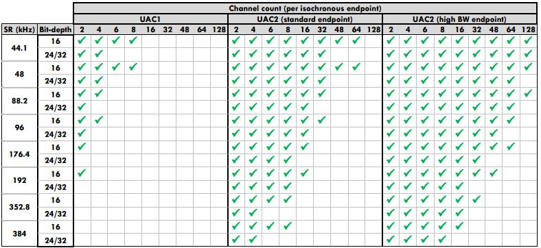
The Ameba USB protocol stack provides a complete UAC device class driver, supporting various mainstream audio formats and sample rates. The specific supported features and parameters are as follows:
UAC 2.0 (High/Full-Speed) class driver, speaker-only, supports following configurable audio parameters:
Sample Rate
Bit-depth
Channel Count
2
4
6
8
44.1
16
Y
Y
Y
Y
24/32
Y
Y
Y
Y
48
16
Y
Y
Y
Y
24/32
Y
Y
Y
Y
96
16
Y
Y
24/32
Y
Y
192
16
Y
24/32
Y
Supports volume/mute control
Fully customizable descriptors
Supports hot-plug
Support speed mode configuration
Note
USB core driver doesn’t support UAC 2.0 high-bandwidth endpoints, max one isochronous OUT transfer per microframe is allowed.
The supported audio formats depend on the whole path of UAC host/device and hardware/software frameworks
UAC 1.0 (Full-Speed) class driver, speaker-only, supports following configurable audio parameters:
Sample Rate
(kHz)
Bit-depth
Channel Count
2
4
6
8
44.1
16
Y
Y
Y
Y
24/32
Y
Y
48
16
Y
Y
Y
Y
24/32
Y
Y
96
16
Y
Y
24/32
Y
192
16
Y
24/32
Supports volume/mute control
Fully customizable descriptors
Supports hot-plug
Support speed mode configuration
Note
The supported audio formats depend on the whole path of UAC host/device and hardware/software frameworks
The UAC (USB Audio Class) protocol defines a standard interface for implementing data transmission and functional control of audio devices within the USB specification framework. Common devices that adhere to this standard include USB microphones, USB headphones, and USB sound cards.
USB-IF has officially released multiple versions of the UAC protocol. The download links for the specification documents of the mainstream versions are shown in the table below:
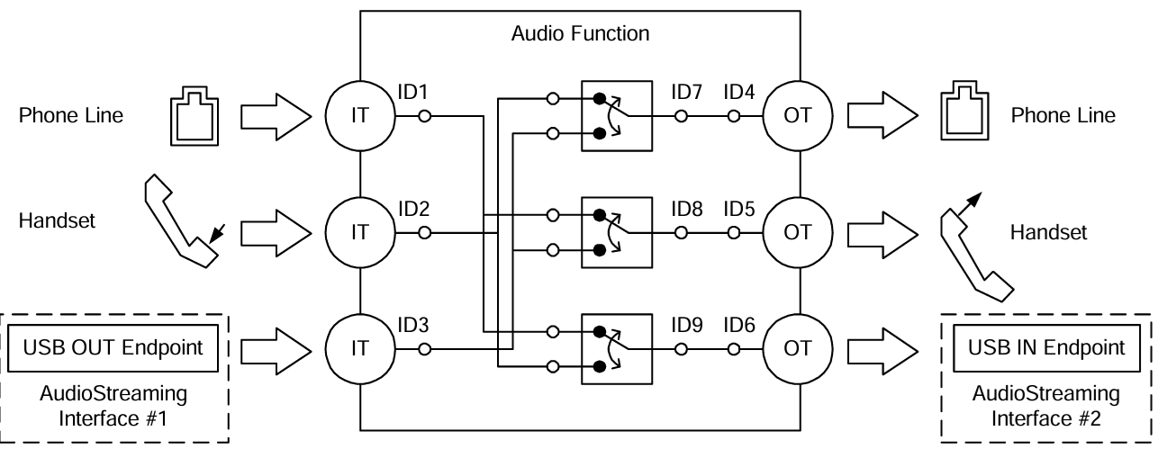
The UAC system architecture supports audio data transmission and control by defining different interface sets. Logically, UAC device interfaces are primarily divided into two major categories: Audio Control Interface and Audio Streaming Interface.
Audio Control (AC) Interface:
Responsible for managing the overall functional behavior of the audio device, such as volume adjustment, mute control, input source selection, etc.
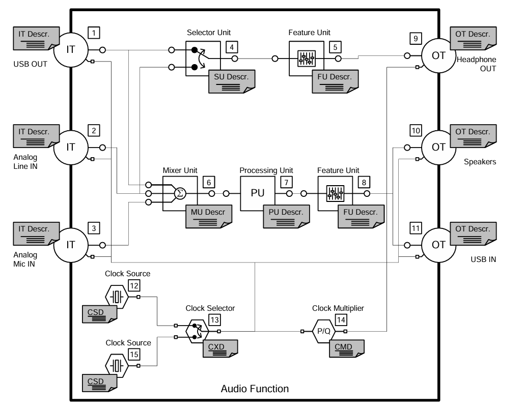
An AC interface contains a defined internal topology that describes the flow and processing of audio signals from the Input Terminal to the Output Terminal.
Audio Streaming (AS) Interface:
Responsible for transmitting the actual audio payload data.
A UAC device can contain multiple AS interfaces, each configurable to transmit audio data with different formats, sampling rates, or bit depths.
In addition to adhering to standard USB descriptors (such as Device Descriptor, Configuration Descriptor, Endpoint Descriptor), UAC devices also define Class-Specific Descriptors. These descriptors are categorized based on their associated interface into Class-Specific Control Interface Descriptors and Class-Specific Audio Streaming Interface Descriptors.
There are differences in descriptor definitions between different protocol versions:
Descriptor Topology
Device Descriptor
└── Identifies basic device information (USB Version 2.00)

Configuration Descriptor
├── Contains total length of the entire configuration, power supply information, etc.
│
├── Interface Association Descriptor (IAD)
│       └── Binds audio control and streaming interfaces into a single functional unit
│
├── Audio Control (AC) Interface Descriptor (Interface 0)
│       ├── Standard Interface Descriptor (Interface 0, Control Class)
│       └── Class-Specific Descriptor Collection
│               ├── Audio Control Interface Header (declares UAC version)
│               ├── Clock Source (internal clock or external clock)
│               ├── Clock Source (internal clock or external clock)
│               ├── Input Terminal (source of audio stream)
│               ├── Feature Unit (volume/mute controls, etc.)
│               ├── Output Terminal (destination of audio stream)
│               ├── Input Terminal (source of audio stream)
│               ├── Feature Unit (volume/mute controls, etc.)
│               └── Output Terminal (destination of audio stream)
│
├── Audio Streaming (AS) Interface Descriptor (Interface 1)
│       ├── Alternate Setting 0: Control transfer active state (control transfer only)
│       │
│       ├── Alternate Setting 1: Data transfer active state (with data endpoint)
│       │ ├── Standard Interface Descriptor (Interface 1, Streaming Class)
│       │ ├── Class-Specific AS Interface (associated USB streaming terminal, audio format, number of channels)
│       │ ├── Format Descriptor (audio format and bit width)
│       │ ├── Standard Endpoint Descriptor (ISO OUT endpoint)
│       │ └── Class-Specific Endpoint Descriptor (no special control)
│       │
│       ├── Alternate Setting 2
│       │ ...... Can configure multiple different setting as needed
│
└── Audio Streaming (AS) Interface Descriptor (Interface 2)
        ├── Alternate Setting 0: Control transfer active state (control transfer only)
        │
        ├── Alternate Setting 1: Data transfer active state (with data endpoint)
        │ ├── Standard Interface Descriptor (Interface 2, Streaming Class)
        │ ├── Class-Specific AS Interface (associated USB streaming terminal, audio format, number of channels)
        │ ├── Format Descriptor (audio format and bit width)
        │ ├── Standard Endpoint Descriptor (ISO IN endpoint)
        │ └── Class-Specific Endpoint Descriptor (no special control)
        │
        ├── Alternate Setting 2
        │ ...... Can configure multiple different setting as needed

Device Qualifier Descriptor
└── Device information while running in another speed mode

Other Speed Configuration Descriptor
├── Configuration information while running in another speed mode.
│
├── Interface Association Descriptor (IAD)
│       └── Binds audio control and streaming interfaces into a single functional unit
│
├── Audio Control (AC) Interface Descriptor (Interface 0)
│       ├── Standard Interface Descriptor (Interface 0, Control Class)
│       └── Class-Specific Descriptor Collection
│               ├── Audio Control Interface Header (declares UAC version)
│               ├── Clock Source (internal clock or external clock)
│               ├── Clock Source (internal clock or external clock)
│               ├── Input Terminal (source of audio stream)
│               ├── Feature Unit (volume/mute controls, etc.)
│               ├── Output Terminal (destination of audio stream)
│               ├── Input Terminal (source of audio stream)
│               ├── Feature Unit (volume/mute controls, etc.)
│               └── Output Terminal (destination of audio stream)
│
├── Audio Streaming (AS) Interface Descriptor (Interface 1)
│       ├── Alternate Setting 0: Control transfer active state (control transfer only)
│       │
│       ├── Alternate Setting 1: Data transfer active state (with data endpoint)
│       │ ├── Standard Interface Descriptor (Interface 1, Streaming Class)
│       │ ├── Class-Specific AS Interface (associated USB streaming terminal, audio format, number of channels)
│       │ ├── Format Descriptor (audio format and bit width)
│       │ ├── Standard Endpoint Descriptor (ISO OUT endpoint)
│       │ └── Class-Specific Endpoint Descriptor (no special control)
│       │
│       ├── Alternate Setting 2
│       │ ...... Can configure multiple different setting as needed
│
└── Audio Streaming (AS) Interface Descriptor (Interface 2)
        ├── Alternate Setting 0: Control transfer active state (control transfer only)
        │
        ├── Alternate Setting 1: Data transfer active state (with data endpoint)
        │ ├── Standard Interface Descriptor (Interface 2, Streaming Class)
        │ ├── Class-Specific AS Interface (associated USB streaming terminal, audio format, number of channels)
        │ ├── Format Descriptor (audio format and bit width)
        │ ├── Standard Endpoint Descriptor (ISO IN endpoint)
        │ └── Class-Specific Endpoint Descriptor (no special control)
        │
        ├── Alternate Setting 2
        │ ...... Can configure multiple different setting as needed
UAC Audio Control (AC) Interface Descriptor
Audio Control Interface Header
Audio Control Interface Header Descriptor
├── bLength            : 1 byte  → Total descriptor length (fixed = 9)
├── bDescriptorType    : 1 byte  → 0x24 (CS_INTERFACE)
├── bDescriptorSubtype : 1 byte  → 0x01 (HEADER)
├── bcdADC             : 2 bytes → Audio Device Class Specification Release Number
├── bCategory          : 1 byte  → Indicates the classification/function of the device
├── wTotalLength       : 2 bytes → Total length of all AC Class-Specific descriptors, including this one
└── bmControls         : 1 byte  → Bitmap indicating the availability of non-addressable control functions
Clock Source Descriptor
Clock Source Descriptor
├── bLength            : 1 byte  → Total descriptor length (fixed = 8)
├── bDescriptorType    : 1 byte  → 0x24 (CS_INTERFACE)
├── bDescriptorSubtype : 1 byte  → 0x0A (Clock Source)
├── bClockID           : 1 byte  → Unique Clock ID, ranging from 1 to 255
├── bmAttributes       : 1 byte  → Clock type (0=Internal, 1=External)
├── bmControls         : 1 byte  → Bitmap indicating the control attributes of the clock
└── iClockSource       : 1 byte  → String descriptor index
Input Terminal Descriptor
Input Terminal Descriptor
├─ bLength                : 1 byte   → Total descriptor length (fixed = 17)
├─ bDescriptorType        : 1 byte   → 0x24 (CS_INTERFACE)
├─ bDescriptorSubtype     : 1 byte   → 0x02 (INPUT_TERMINAL)
├─ bTerminalID            : 1 byte   → Unique ID of this terminal (referenced in topology)
├─ wTerminalType          : 2 bytes  → Terminal type (little-endian)
│                           ├─ 0x0101 = USB Streaming (Host audio stream input)
│                           └─ Other values refer to UAC2.0 Appendix B (e.g., Microphone)
├─ bAssocTerminal         : 1 byte   → Associated Output Terminal ID (0 = no pairing)
├─ bCSourceID             : 1 byte   → Associated Clock Source ID
├─ bNrChannels            : 1 byte   → Number of logical output channels (e.g., 2 = stereo)
├─ bmChannelConfig        : 4 bytes  → Spatial location bitmap for channels
├─ iChannelNames          : 1 byte   → String index for channel names
├─ bmControls             : 2 byte   → Control bitmap
└─ iTerminal              : 1 byte   → String index for describing this terminal
Feature Unit Descriptor
Feature Unit Descriptor
├─ bLength                : 1 byte   → otal descriptor length in bytes
│                                      = 6 + (1 + bNrChannels) × 4
├─ bDescriptorType        : 1 byte   → = 0x24 (CS_INTERFACE)
├─ bDescriptorSubtype     : 1 byte   → = 0x06 (FEATURE_UNIT)
├─ bUnitID                : 1 byte   → Unique ID of this Feature Unit
├─ bSourceID              : 1 byte   → ID of the connected Source Unit or Terminal
├─ bmaControls[0]         : 4 bytes  → Master Channel Control Bitmap
├─ bmaControls[1]         : 4 bytes  → Logical Channel 1 Control Bitmap
├─ bmaControls[2]         : 4 bytes  → Logical Channel 2 Control Bitmap
│    ⋮
├─ bmaControls[N]         : 4 bytes  → Logical Channel N Control Bitmap (Total bNrChannels entries)
└─ iFeature               : 1 byte   → String descriptor index
Output Terminal Descriptor
Output Terminal Descriptor
├─ bLength                : 1 byte   → Total descriptor length (fixed = 12 bytes)
├─ bDescriptorType        : 1 byte   → 0x24 (CS_INTERFACE)
├─ bDescriptorSubtype     : 1 byte   → 0x03 (OUTPUT_TERMINAL)
├─ bTerminalID            : 1 byte   → Unique ID of this terminal
├─ wTerminalType          : 2 bytes  → Terminal type
│                           ├─ 0x0301 = Speaker
│                           ├─ 0x0302 = Headphones
│                           ├─ 0x0603 = SPDIF
│                           └─ Other values refer to Appendix B
├─ bAssocTerminal         : 1 byte   → Associated Input Terminal ID
├─ bSourceID              : 1 byte   → ID of the connected Source Unit or Terminal
├─ bCSourceID             : 1 byte   → Associated Clock Source ID
└─ iTerminal              : 1 byte   → String index for describing this terminal
Audio Streaming Interface Descriptor
Class-Specific AS Interface Descriptor
Class-Specific AS Interface Descriptor
├─ bLength                : 1 byte   → Fixed as 0x10 (16 bytes)
├─ bDescriptorType        : 1 byte   → 0x24(CS_INTERFACE)
├─ bDescriptorSubtype     : 1 byte   → 0x01(AS_GENERAL)
├─ bTerminalLink          : 1 byte   → Associated Terminal ID (Input or Output Terminal)
├─ bmControls             : 1 bytes  → Bitmap of endpoint control capabilities
├─ bFormatType            : 1 byte   → Format type
│                           └─ 0x01 = FORMAT_TYPE_I(PCM)
├─ bmFormats              : 4 bytes  → Bitmap of supported audio formats
├─ bNrChannels            : 1 bytes  → Number of supported audio channels
├─ bmChannelConfig        : 4 bytes  → Supported audio channel configuration bitmap
└─ iChannelNames          : 1 byte   → String index for channel names
Audio Streaming Format Type Descriptor
Audio Streaming Format Type Descriptor
├─ bLength            : 1 byte   → Total length of descriptor in bytes (6 bytes)
├─ bDescriptorType    : 1 byte   → = 0x24(CS_INTERFACE)
├─ bDescriptorSubtype : 1 byte   → = 0x02(FORMAT_TYPE)
├─ bFormatType        : 1 byte   → = 0x01(FORMAT_TYPE_I)
├─ bSubslotSize       : 1 byte   → Container size for each audio sample (in bytes)
│                                   • Typical values: 1, 2, 3, 4
├─ bBitResolution     : 1 byte   → Number of valid bits in each sample(≤ bSubslotSize × 8)
└─                                  • Example: 16 represents 16-bit PCM
Descriptor Topology
Device Descriptor
└── Identifies basic device information (USB Version 1.10)

Configuration Descriptor
├── Contains total length of the entire configuration, power supply information, etc.
│
├── Audio Control (AC) Interface Descriptor (Interface 0)
│       ├── Standard Interface Descriptor (AlternateSetting 0, Control Class)
│       └── Class-Specific Descriptor Collection
│               ├── Audio Control Interface Header (declares UAC version)
│               ├── Input Terminal (source of audio stream)
│               ├── Feature Unit (volume/mute controls, etc.)
│               ├── Output Terminal (destination of audio stream)
│               ├── Input Terminal (source of audio stream)
│               ├── Feature Unit (volume/mute controls, etc.)
│               └── Output Terminal (destination of audio stream)
│
├── Audio Streaming (AS) Interface Descriptor (Interface 1)
│       ├── Alternate Setting 0: Control transfer active state (control transfer only)
│       │
│       ├── Alternate Setting 1: Data transfer active state (with data endpoint)
│       │ ├── Standard Interface Descriptor (Interface 1, Streaming Class)
│       │ ├── Class-Specific AS Interface (associated USB streaming terminal)
│       │ ├── Format Descriptor (audio format:channel, bit width and frequency)
│       │ ├── Standard Endpoint Descriptor (ISO OUT endpoint)
│       │ └── Class-Specific Endpoint Descriptor (no special control)
│       │
│       ├── Alternate Setting 2
│       │ ...... Can configure multiple different setting as needed
│
└── Audio Streaming (AS) Interface Descriptor  (Interface 2)
        ├── Alternate Setting 0: Control transfer active state (control transfer only)
        │
        ├── Alternate Setting 1: Data transfer active state (with data endpoint)
        │ ├── Standard Interface Descriptor (Interface 2, Streaming Class)
        │ ├── Class-Specific AS Interface (associated USB streaming terminal)
        │ ├── Format Descriptor (audio format:channel, bit width and frequency)
        │ ├── Standard Endpoint Descriptor (ISO IN endpoint)
        │ └── Class-Specific Endpoint Descriptor (no special control)
        │
        ├── Alternate Setting 2
        │ ...... Can configure multiple different setting as needed
UAC Audio Control (AC) Interface Descriptor
Audio Control Interface Header
Audio Control Interface Header Descriptor
├── bLength            : 1 byte  → Total descriptor length (typically 9 + bInCollection × 1)
├── bDescriptorType    : 1 byte  → 0x24 (CS_INTERFACE)
├── bDescriptorSubtype : 1 byte  → 0x01 (HEADER)
├── bcdADC             : 2 bytes → Audio Device Class Specification Release Number (0x0100)
├── wTotalLength       : 2 byte  → Total number of bytes for all AC descriptors (including this header and all Unit/Terminal descriptors)
├── baInterfaceNr(1)   : 1 byte  → Interface number of the first AudioStreaming or MIDIStreaming interface in the Collection.
│    ⋮
└── baInterfaceNr(N)   : 1 byte  → Interface number of the last AudioStreaming or MIDIStreaming interface in the Collection.
Input Terminal Descriptor
Clock Source Descriptor
├── bLength            : 1 byte  → Total descriptor length (fixed = 12)
├── bDescriptorType    : 1 byte  → 0x24 (CS_INTERFACE)
├── bDescriptorSubtype : 1 byte  → 0x0A (Clock Source)
├── bTerminalID        : 1 byte  → Constant uniquely identifying the Terminal within the audio function.
├── wTerminalType      : 2 bytes → Constant characterizing the type of Terminal.
├── bAssocTerminal     : 1 byte  → D of the Output Terminal to which this Input Terminal is associated.
├── bNrChannels        : 1 byte  → Number of logical output channels in the Terminal’s output audio channel cluster.
├── wChannelConfig     : 2 bytes → Describes the spatial location of the logical channels.
├── iChannelNames      : 1 byte  → Index of a string descriptor, d
└── iTerminal          : 1 byte  → String descriptor index
Feature Unit Descriptor
Feature Unit Descriptor
├─ bLength                : 1 byte   → otal descriptor length in bytes = 7+(ch+1)*n
├─ bDescriptorType        : 1 byte   → = 0x24 (CS_INTERFACE)
├─ bDescriptorSubtype     : 1 byte   → = 0x06 (FEATURE_UNIT)
├─ bUnitID                : 1 byte   → Unique ID of this Feature Unit
├─ bSourceID              : 1 byte   → ID of the connected Source Unit or Terminal
├─ bControlSize           : 1 byte   → Size in bytes of an element of the bmaControls() array: n
├─ bmaControls[0]         : n bytes  → A bit set to 1 indicates that the mentioned Control is supported for master channel
├─ bmaControls[1]         : n bytes  → A bit set to 1 indicates that the mentioned Control is supported for logical channel1
│    ⋮
├─ bmaControls[N]         : n bytes  → A bit set to 1 indicates that the mentioned Control is supported for logical channel ch
└─ iFeature               : 1 byte   → String descriptor index
Output Terminal Descriptor
Output Terminal Descriptor
├─ bLength                : 1 byte   → Total descriptor length (fixed = 9 bytes)
├─ bDescriptorType        : 1 byte   → 0x24 (CS_INTERFACE)
├─ bDescriptorSubtype     : 1 byte   → 0x03 (OUTPUT_TERMINAL)
├─ bTerminalID            : 1 byte   → Unique ID of this terminal
├─ wTerminalType          : 2 bytes  → Terminal type
│                           ├─ 0x0301 = Speaker
│                           ├─ 0x0302 = Headphones
│                           ├─ 0x0603 = SPDIF
│                           └─ Other values refer to Appendix B
├─ bAssocTerminal         : 1 byte   → Associated Input Terminal ID
├─ bSourceID              : 1 byte   → ID of the connected Source Unit or Terminal
└─ iTerminal              : 1 byte   → String index for describing this terminal
Audio Streaming Interface Descriptor
Class-Specific AS Interface Descriptor
Class-Specific AS Interface Descriptor
├─ bLength                : 1 byte   → Fixed as 0x07 (7 bytes)
├─ bDescriptorType        : 1 byte   → 0x24(CS_INTERFACE)
├─ bDescriptorSubtype     : 1 byte   → 0x01(AS_GENERAL)
├─ bTerminalLink          : 1 byte   → Associated Terminal ID (Input or Output Terminal)
├─ bDelay                 : 1 bytes  → Delay introduced by this interface (in number of frames)
└─ wFormatTag             : 2 byte   → Audio data format (e.g., 0x0001 = PCM)
Audio Streaming Format Type Descriptor
Audio Streaming Format Type Descriptor
├─ bLength            : 1 byte   → Total length of descriptor in bytes (8 + (num_freq × 3))
├─ bDescriptorType    : 1 byte   → = 0x24(CS_INTERFACE)
├─ bDescriptorSubtype : 1 byte   → = 0x02(FORMAT_TYPE)
├─ bFormatType        : 1 byte   → = 0x01(FORMAT_TYPE_I)
├─ bNrChannels        : 1 byte   → Number of channels (e.g., 2)
├─ bSubslotSize       : 1 byte   → Container size for each audio sample (in bytes)
│                                   • Typical values: 1, 2, 3, 4
├─ bBitResolution     : 1 byte   → Number of valid bits in each sample(≤ bSubslotSize × 8)
├─                                  • Example: 16 represents 16-bit PCM
├─ bSamFreqType       : 1 byte   → sampling frequency count
└─ tSamFreq(n)        : 3×n byte → Sample rates in little-endian 3-byte format
Note
For detailed field definitions, please refer to the official USB-IF UAC protocol documentation.
The control requests for UAC devices are divided into Standard Requests and Class-Specific Requests.
This section primarily introduces the Class-Specific Requests unique to UAC. These requests are used to implement the distinctive features of audio devices and mainly include Audio Control Requests (targeting AC interfaces) and Audio Streaming Requests (targeting AS interfaces).
Audio Control Requests (AC Requests)
AC Requests are class-specific control transfers sent by the host over Endpoint 0 to dynamically configure and manage audio functionality within a USB audio device.
AudioControl Type
Required
Description
Mute Control Request
Optional
Manipulate the mute control in the Feature Unit of the audio function
Volume Control Request
Optional
Manipulate the volume control in the Feature Unit of the audio function
Sampling Frequency Control
Optional
Manipulate the actual sampling frequency of the clock signal.
Mixer Unit Control Request
Optional
Manipulate the control inside a Mixer Unit of the audio function
Terminal Control Request
Optional
Manipulate the control inside a Mixer Unit of the audio function
Selector Unit Control Request
Optional
Manipulate the control inside a Selector Unit of the audio function
Effect Unit Control Request
Optional
Manipulate the Controls inside an Effect Unit of the audio function
Processing Unit Control Request
Optional
Manipulate the Controls inside a Processing Unit of the audio function
Extension Unit Control Requests
Optional
Manipulate the Controls inside an Extension Unit of the audio function
Audio Streaming Requests (AS Requests)
AS Requests are class-specific control transfers issued by the host over Endpoint 0 to configure and manage parameters related to audio data streams, pecifically those associated with an Audio Streaming Interface.
AudioStreaming Type
Required
Description
Interface Control Request
Optional
Manipulate the Controls inside an AudioStreaming interface of the audio function
Encoder Control Request
Optional
Manipulate the Encoder Controls inside an AudioStreaming interface of the audio function
Decoder Control Request
Optional
Manipulate the Decoder Controls inside an AudioStreaming interface of the audio function
Endpoint Control Request
Optional
Manipulate the Controls inside an AudioStreaming endpoint of the audio function
Audio Control Requests (AC Requests)
Audio Control Requests (AC Requests) are class-specific control transfers sent by the host over Endpoint 0 to dynamically configure and manage audio functionality within a USB audio device.
AudioControl Type
Required
Description
Mute Control Request
Optional
Manipulate the mute control in the Feature Unit of the audio function
Volume Control Request
Optional
Manipulate the volume control in the Feature Unit of the audio function
Mixer Unit Control Request
Optional
Manipulate the control inside a Mixer Unit of the audio function
Selector Unit Control Request
Optional
Manipulate the control inside a Selector Unit of the audio function
Processing Unit Control Request
Optional
Manipulate the Controls inside a Processing Unit of the audio function
Extension Unit Control Requests
Optional
Manipulate the Controls inside an Extension Unit of the audio function
Audio Streaming Requests (AS Requests)
Audio Streaming Requests (AS Requests) are class-specific control transfers issued by the host over Endpoint 0 to configure and manage parameters related to audio data streams, pecifically those associated with an Audio Streaming Interface.
AudioStreaming Type
Required
Description
Interface Control Request
Optional
Manipulate the Controls inside an AudioStreaming interface of the audio function
Endpoint Control Request
Optional
Describe the requests that the audio function can support for its AudioStreaming endpoint
This section explains the transmission format of UAC audio data streams. UAC typically transmits PCM data in a multi-channel interleaved format. The specific data arrangement depends on the channel count and bit depth.
An example of 2-Channel interleaved data is shown below:
An example of 4-Channel interleaved data is shown below:
An example of N-Channel interleaved data is shown below:
Note
Channel Alignment Rule:
The UAC protocol typically requires the transmitted number of channels to be a power of two (e.g., 2, 4, 8, 16, etc.). If the actual physical channel count (e.g., 10 channels) does not comply with this rule, it must be rounded up to the nearest power of two (configured for transmission as 16 channels). The extra channel positions are filled with invalid data.
This section presents the UAC class-specific descriptor structures defined at the driver layer. These structures correspond to the standard descriptor definitions in the USB protocol specification.
Device Descriptor
└─ USB Version 2.00

Configuration Descriptor(Interfaces 2)
│
├─ Interface Association Descriptor (IAD)
├── Binds audio control and streaming interfaces into a single functional unit
│
├─ AudioControl Interface (IF 0, Alt 0)
│  ├─ Audio Control Interface Header (Header 2.0, desktop speaker)
│  ├─ Clock Source (ID=0x15, Internal, Sync to SOF)
│  ├─ Input Terminal (ID=0x01, USB Streaming)
│  ├─ Feature Unit (ID=0x05, Mute+Volume, 8 ch)
│  └─ Output Terminal (ID=0x09, Speaker, clocked=0x15)
│
└─ AudioStreaming Interface (IF 1)
   ├─ Alt 0: Inactive (no endpoints)
   │
   ├─ Alt 1: 16-bit | 2 ch | PCM
   │        AS Interface: TerminalLink(0x01) channels(2)
   │        AS Format: BitResolution(16)
   │        Endpoint: ISO OUT, maxpkt=0x001C (28 bytes)
   │
   ├─ Alt 2: 16-bit | 4 ch | PCM
   │        AS Interface: TerminalLink(0x01) channels(4)
   │        AS Format: BitResolution(16)
   │        Endpoint: ISO OUT, maxpkt=0x0038 (56 bytes)
   │
   ├─ Alt 3: 16-bit | 6 ch | PCM
   │        AS Interface: TerminalLink(0x01) channels(6)
   │        AS Format: BitResolution(16)
   │        Endpoint: ISO OUT, maxpkt=0x0054 (84 bytes)
   │
   ├─ Alt 4: 16-bit | 8 ch | PCM
   │        AS Interface: TerminalLink(0x01) channels(8)
   │        AS Format: BitResolution(16)
   └        Endpoint: ISO OUT, maxpkt=0x0070 (112 bytes)

Device Qualifier Descriptor
└─ USB 2.0

Other Speed Configuration Descriptor(Interfaces 2)
│
├─ Interface Association Descriptor (IAD)
├── Binds audio control and streaming interfaces into a single functional unit
│
├─ AudioControl Interface (IF 0, Alt 0)
│  ├─ Audio Control Interface Header (Header 2.0, desktop speaker)
│  ├─ Clock Source (ID=0x15, Internal, Sync to SOF)
│  ├─ Input Terminal (ID=0x01, USB Streaming)
│  ├─ Feature Unit (ID=0x05, Mute+Volume, 8 ch)
│  └─ Output Terminal (ID=0x09, Speaker, clocked=0x15)
│
└─ AudioStreaming Interface (IF 1)
   ├─ Alt 0: Inactive (no endpoints)
   │
   ├─ Alt 1: 16-bit | 2 ch | PCM
   │        AS Interface: TerminalLink(0x01) channels(2)
   │        AS Format: BitResolution(16)
   │        Endpoint: ISO OUT, maxpkt=0x00C4 (196 bytes)
   │
   ├─ Alt 2: 16-bit | 4 ch | PCM
   │        AS Interface: TerminalLink(0x01) channels(4)
   │        AS Format: BitResolution(16)
   │        Endpoint: ISO OUT, maxpkt=0x0188 (392 bytes)
   │
   ├─ Alt 3: 16-bit | 6 ch | PCM
   │        AS Interface: TerminalLink(0x01) channels(6)
   │        AS Format: BitResolution(16)
   │        Endpoint: ISO OUT, maxpkt=0x024C (588 bytes)
   │
   ├─ Alt 4: 16-bit | 8 ch | PCM
   │        AS Interface: TerminalLink(0x01) channels(8)
   │        AS Format: BitResolution(16)
   └        Endpoint: ISO OUT, maxpkt=0x0310 (784 bytes)
Device Descriptor
└─ USB Version 1.10

Configuration Descriptor(Interfaces 2)
│
├─ AudioControl Interface (Interfaces 0, Alt 0)
│  ├─ Audio Control Interface Header (bcdADC 0x0110)
│  ├─ Input Terminal (ID=0x01, USB Streaming)
│  ├─ Feature Unit (ID=0x05, Mute+Volume, 8 ch)
│  └─ Output Terminal (ID=0x09, Speaker)
│
└─ AudioStreaming Interface (Interfaces 1)
   ├─ Alt 0: Inactive (no endpoints)
   │
   ├─ Alt 1: 16-bit | 2 ch | PCM
   │        AS Interface: TerminalLink(0x01)
   │        AS Format: Channels(2), BBitResolution(16), SamFreq(44100,48000)
   │        Endpoint: ISO OUT, maxpkt=0x00C4 (196 bytes)
   │
   ├─ Alt 2: 16-bit | 4 ch | PCM
   │        AS Interface: TerminalLink(0x01)
   │        AS Format: Channels(4), BitResolution(16), SamFreq(44100,48000)
   │        Endpoint: ISO OUT, maxpkt=0x0188 (392 bytes)
   │
   ├─ Alt 3: 16-bit | 6 ch | PCM
   │        AS Interface: TerminalLink(0x01)
   │        AS Format: Channels(6), BitResolution(16), SamFreq(44100,48000)
   │        Endpoint: ISO OUT, maxpkt=0x024C (588 bytes)
   │
   ├─ Alt 4: 16-bit | 8 ch | PCM
   │        AS Interface: TerminalLink(0x01)
   │        AS Format: Channels(8), BitResolution(16), SamFreq(44100,48000)
   └        Endpoint: ISO OUT, maxpkt=0x0310 (784 bytes)
The driver has implemented the core class-specific requests defined by the UAC specification, primarily including Sampling Frequency Control, Volume Control, and Mute Control.
Developers can refer to the existing implementation to extend other types of requests. The UAC driver source code path is: {SDK}/component/usb/device/uac
Audio Control Requests (AC Requests)
AudioControl Type
Required
Note
Mute Control Request
Optional
Control the Current Sound Mute Function
Volume Control Request
Optional
Control the Current Sound Volume Function
Sampling Frequency Control Request
Optional
Control the Current Sound Sampling Frequency Function
Audio Streaming Requests (AS Requests)
AudioStreaming Type
Required
Note
Interface Control Request
Optional
Switching between different interfaces to choose the different audio format.
This section outlines the complete usage flow of the UAC driver, covering core aspects such as initialization, hot-plug management, audio data processing, and configuration changes.
Define the configuration structure, register callback functions, and then call the initialization interface to load the USB device core and the UAC class driver.
/* Configure different USB speeds according to different UAC applications UAC 1.0 only support full speed, while UAC 2.0 can support both full speed and high speed*/staticusbd_config_tuac_cfg={.speed=CONFIG_USBD_UAC_SPEED,.isr_priority=INT_PRI_MIDDLE,};staticusbd_uac_cb_tuac_cb={.in={.enable=1,},/* Audio out params */.out={.enable=0,},/* Audio in params */.init=uac_cb_init,/* USB init callback */.deinit=uac_cb_deinit,/* USB deinit callback */.setup=uac_cb_setup,/* USB setup callback */.set_config=uac_cb_set_config,/* USB set_config callback */.status_changed=uac_cb_status_changed,/* USB status change callback */.mute_changed=uac_cb_mute_changed,/* Audio mute change callback */.volume_changed=uac_cb_volume_changed,/* Audio volume change callback */.format_changed=uac_cb_format_changed,/* Audio format change callback */};intret=0;/** * Initialize USB device core driver with configuration. * param[in] cfg: USB device configuration. * return 0 on success, non-zero on failure. */ret=usbd_init(&uac_cfg);if(ret!=HAL_OK){return;}/** * Initializes class driver with application callback handler. * param[in] cb: Pointer to the user-defined callback structure. * return 0 on success, non-zero on failure. */ret=usbd_uac_init(&uac_cb);if(ret!=HAL_OK){/** * Deinitialize USB device core driver. * return 0 on success, non-zero on failure. */usbd_deinit();return;}
Monitor USB connection status changes (connected/disconnected) by registering the status_changed callback function. It is recommended to use a semaphore to notify a dedicated task thread for processing, avoiding time-consuming operations within interrupt context.
/* USB status change callback */staticusbd_uac_cb_tuac_cb={.status_changed=uac_cb_status_changed,};/* Callback executed in ISR context */staticvoiduac_cb_status_changed(u8old_status,u8status){uac_attach_status=status;rtos_sema_give(uac_attach_status_changed_sema);}/* Thread handling the state machine */staticvoiduac_hotplug_thread(void*param){intret=0;UNUSED(param);for(;;){if(rtos_sema_take(uac_attach_status_changed_sema,RTOS_SEMA_MAX_COUNT)==RTK_SUCCESS){if(uac_attach_status==USBD_ATTACH_STATUS_DETACHED){RTK_LOGS(TAG,RTK_LOG_INFO,"DETACHED\n");/* Clean up resources */usbd_uac_deinit();ret=usbd_deinit();if(ret!=0){break;}/* Re-initialize for next connection */ret=usbd_init(&uac_cfg);if(ret!=0){break;}ret=usbd_uac_init(&uac_cb);if(ret!=0){usbd_deinit();break;}}elseif(uac_attach_status==USBD_ATTACH_STATUS_ATTACHED){RTK_LOGS(TAG,RTK_LOG_INFO,"ATTACHED\n");}else{RTK_LOGS(TAG,RTK_LOG_INFO,"INIT\n");}}}RTK_LOGS(TAG,RTK_LOG_INFO,"Hotplug thread fail\n");rtos_task_delete(NULL);}
Call usbd_uac_config() to apply new parameters, and call usbd_uac_start_play() to initiate data reception. It is recommended to check the startup status in a loop to handle unstable cable connections.
For the complete playback logic (including interaction with hardware Codec), please refer to the SDK example code: {SDK}/component/example/usb/usbd_uac/example_usbd_uac.c. Ensure that CONFIG_USBD_AUDIO_EN is set to 1.
This section introduces a complete USB Audio Class (UAC) speaker application example, demonstrating how to configure the Ameba development board as a USB audio output device via the UAC protocol stack.
When the development board is connected to a PC, the system recognizes it as a speaker. Digital audio streams played on the PC are transmitted to the development board via USB and output in analog form via the onboard Codec/speaker.
The example code path is: {SDK}/component/example/usb/usbd_uac. It provides a complete reference solution for developers designing custom USB audio products.
In the amebaxxx_gcc_project directory, type ./menuconfig.py, and follow the steps below to select USBDUAC and AudioFramework. Save and exit.
- Choose `CONFIG USB --->`:
        [*] Enable USB
                        USB Mode (Device)  --->

- Choose UAC version 1.0 or 2.0 :
        [*] UAC
                        Select UAC Version (UAC 2.0)  --->

- Choose `CONFIG APPLICATION --->`
        `Audio Config --->`:
                [*] Enable Audio Framework
                                Select Audio Interfaces (PassThrough)  --->
Note
If audio playback is not smooth, change the AudioFramework configuration to SelectAudioInterfaces(Mixer). Refer to the audio module for more information.
Compilation and Flashing
Compile according to the instructions below, and flash the image file to the development board. After flashing successfully, restart the board.
Reboot the development board and monitor the serial log. The following initialization message should be displayed:
[UAC-I] USBD uac demo start
Connect to Host
Connect the development board to a PC (e.g., a Windows computer) using a USB cable.
System Recognition
The audio device named "RealtekUACDevicespeakerdevice" should appear in the Windows Sound settings.
Note
If the Ameba audio device is not visible, open the computer’s sound control panel and locate the “Realtek UAC Device speaker device”.
Ensure it is Enabled (if not, right-click and select Enable).
Set it as the default device (right-click and select SetasDefaultDevice).
Format Switching Test
Try switching between different bit depths and sample rates (e.g., 16-bit 48000Hz) to verify that the device successfully re-negotiates the connection and plays audio normally.
The INIC (Internet Network Interface Controller) enables a USB-based FullMAC implementation, functioning as a network interface card to provide host connectivity via USB.
The USB Composite Device specification defines the device architecture and enumeration standards for carrying multiple independent function classes (such as Audio, HID, Storage, Serial, etc.) through a single physical USB interface.
Based on the USB specification officially released by the USB-IF, Ameba implements a flexible composite device functional framework.
It supports aggregating multiple functional interfaces via Interface Descriptors or Interface Association Descriptors (IAD), providing capabilities for parallel enumeration, independent driver loading, and collaborative operation of multiple logical devices on the host side.
As a USB composite device, Ameba can simultaneously enumerate multiple device classes through a single USB physical interface, enabling parallel processing of data transmission and control interaction. It is suitable for a wide range of complex application scenarios. For example,
USB Audio Device with Remote Control (UAC + HID): Ameba provides USB audio input/output functionality (UAC) while utilizing the HID interface for media control. Users can enjoy a high-quality audio streaming experience (such as listening to music through headphones or recording with a microphone), and also interact with features like volume adjustment, muting, song switching, or RGB lighting effects control through the HID channel.
Smart Industry and 3D Printing Control (MSC + CDC ACM): Ameba combines the MSC high-capacity storage and CDC virtual serial port functions. In 3D printer or data logger scenarios, the MSC interface can be simulated as a USB flash drive for storing G-code slicing files or sensor historical data, while the CDC interface simultaneously serves as a console for the host computer to send AT commands in real time, monitor temperature, or calibrate parameters.
Automated Testing and Assistive Input (HID Mouse + CDC ACM): Ameba combines the HID mouse and CDC serial port functions. In this scenario, the CDC interface is responsible for receiving raw data (such as coordinate instructions, head tracking data) from backend scripts or sensors, while the HID interface simulates cursor movement and click actions based on these instructions. It is widely used in hardware automated testing tools or assistive input devices for the disabled.
The USB Composite Device specification defines a device architecture capable of supporting multiple independent function interfaces via a single physical interface within the USB framework.
This mechanism enables the host to identify and enumerate a single physical device as a collection of logical functions, facilitating parallel processing and independent control across different device classes (e.g., HID, MSC, CDC).
Common implementations include wireless keyboard/mouse receivers, USB headsets with integrated audio cards, and industrial devices combining storage and debugging capabilities.
While adhering to standard USB descriptors (Device and Configuration Descriptors), composite devices define multi-functionality by aggregating multiple Interface Descriptors within the Configuration Descriptor set.
When a single interface represents a standalone function, the composite device simply aggregates these functional classes. Typical examples of single-interface function classes include HID and MSC.
Taking a HID Keyboard + HID Mouse composite device as an example, the descriptor topology is illustrated below:
HID Keyboard + HID Mouse composite device compared to individual keyboard/mouse devices, with descriptor characteristics as follows:
Descriptor Level
Single Function Device
Composite Device
Device Descriptor
bDeviceClass defines the type
bDeviceClass is typically 0xEF (Misc) or 0x00 (Defined by Interface)
Configuration Descriptor
1 Configuration
1 Configuration
Interface Descriptor
1 Interface
2 (or more) Interfaces
Endpoint Descriptor
Belong to the single interface
Each interface has independent endpoints
Note
bDeviceClass=0xEF: This is a standard flag for composite devices, which triggers the host driver to parse the IAD (optional) and multiple interface descriptors in the configuration descriptor,
decompose different device functions, and create these logical sub-devices. Then load the keyboard driver for Interface 0 and the mouse driver for Interface 1.
If a logical function requires the use of multiple interfaces to complete, the Interface Association Descriptor (IAD) must be included when using this type of function to associate these interfaces.
Typical multi-interface functional class
CDC (Communication Device Class): Typically requires 1 Control Interface (CCI) + 1 Data Interface (DCI).
UVC (USB Video Class): Requires 1 Video Control Interface (VC) + 1 or more Video Streaming Interfaces (VS).
UAC (USB Audio Class): Requires 1 Audio Control Interface (AC) + 1 or more Audio Stream Interfaces (AS).
Interface Association Descriptor (IAD)
IAD declares to the host that a set of consecutive interfaces that follow closely belong to the same function and should be loaded and managed by the same driver. Without IAD, the host sometimes recognizes them as two separate devices, or the driver fails to load.
Interface Association Descriptor (IAD)
├── bLength                 : 1 byte  → 0x08 (Fixed Length)
├── bDescriptorType         : 1 byte  → 0x0B (IAD type code)
├── bFirstInterface         : 1 byte  → First Interface Number
├── bInterfaceCount         : 1 bytes → Count of associated interfaces
├── bFunctionClass          : 1 byte  → Function Class Code
├── bFunctionSubClass       : 1 byte  → Function SubClass Code
├── bFunctionProtocol       : 1 byte  → Function Protocol Code
└── iFunction               : 1 byte  → Function String Descriptor Index
IAD Usage Example
Function 1: Class utilize two interfaces. In order for the host to recognize them as a single logical function, it is necessary to use IAD to associate these two interfaces.
Function 2: Class utilize a separate interface, eliminating the need for IAD association.
Composite devices do not have a dedicated “composite device class request”. Their core logic lies in precisely directing Class-Specific Requests to the designated interface through the addressing mechanism in USB standard requests.
In the bmRequestType field of the SETUP packet, the lower 5 bits (Bits 0..4) represent the Recipient.
General single-function device: Control requests are typically sent to the “entire device”, meaning the Recipient is set to Device(00000).
Composite device: A large number of control requests must be precisely sent to a “specific interface”, which means setting the Recipient to Interface(00001).
The following are the most notable key points regarding the handling of control requests by composite devices:
Field
Value
Meaning
Implementation in Composite Devices
bmRequestType
0x21 / 0xA1
Class Request, Recipient=Interface
Most common scenario. Examples include setting CDC baud rates or
controlling HID keyboard LEDs.
wIndex
Interface Number
Interface Number
When the Recipient is Interface, wIndex must specify the target interface
index (e.g., 0, 1, 2). The driver routes the request to the corresponding
function driver based on this value.
This section provides a detailed analysis of how to design and implement a USB composite device class driver. The composite class driver acts as a “parent class,” responsible for managing resource scheduling, request dispatching, and data processing for multiple “child classes” (such as CDC ACM, HID, MSC, etc.).
To allow the host to correctly identify the composite device and the multiple functions it contains, the driver must dynamically assemble a complete and precise set of descriptors at runtime. The following points must be noted when generating device descriptors:
Device Descriptor
bDeviceClass: Usually set to 0xEF (Miscellaneous) or 0x00 (defined by the interface).
Configuration Descriptor
This is a dynamically generated “aggregate” that contains the descriptors for all sub-functions.
bNumInterfaces: Must be the sum of the number of interfaces for all sub-functions. For example, for a composite device consisting of a CDC function (occupying 2 interfaces) and an MSC function (occupying 1 interface), this value should be 3.
wTotalLength: Must be the sum of the lengths of all descriptors (Configuration, IAD, Interface, Endpoint). This value needs to be calculated precisely at runtime.
Interface Association Descriptor (IAD): If a sub-function contains multiple interfaces (e.g., CDC ACM), an IAD must be used to “bundle” these interfaces together, declaring that they belong to the same function.
Endpoint Descriptor
The configuration of endpoints must be tailored to the hardware capabilities of the chip. Please refer to Hardware Configuration for details.
Endpoint selection: Available endpoints must be selected based on functional requirements (IN/OUT) and hardware support.
Maximum Packet Size (MPS): Hardware limitations need to be considered. Especially when using a dedicated transmit buffer, it is important to ensure that the size of the transmit buffer area of the IN endpoint can accommodate at least one maximum packet.
The following section illustrates the descriptor topology of the CDC ACM + MSC composite device. These structures correspond to the standard descriptor definitions in the USB protocol specifications.
CDC ACM (Virtual Serial Port): Occupies two interfaces. To ensure the host recognizes them as a single logical function, an IAD (Interface Association Descriptor) must be used to associate these two interfaces.
MSC (Mass Storage): Operates as an independent interface and does not require IAD association.
The composite device (CDC ACM + MSC) solution utilizes 5 non-zero endpoints (excluding the default control endpoint EP0).
Interface number
Interface Class
Endpoints
Description
Interface 0
CDC Control (ACM)
1x Interrupt IN
Used to notify Serial State and management commands.
Interface 1
CDC Data
1x Bulk OUT, 1x Bulk IN
Responsible for sending (OUT) and receiving (IN) virtual
serial port data.
Interface 2
MSC (Mass Storage)
1x Bulk OUT, 1x Bulk IN
Responsible for data read/write of the mass storage device
(SCSI commands/data).
In the class driver, various descriptors are generally defined as arrays. When obtaining configuration descriptors, the callback function get_descriptor of each sub-function class driver is called sequentially to aggregate them together.
/* USB Standard Device Descriptor */staticconstu8usbd_composite_dev_desc[USB_LEN_DEV_DESC]={//...0xEF,/* bDeviceClass: Miscellaneous */0x02,/* bDeviceSubClass: Common Class */0x01,/* bDeviceProtocol: Interface Association Descriptor *///...};/* USB Standard Configuration Descriptor */staticconstu8usbd_composite_config_desc[USB_LEN_CFG_DESC]={//...0x00,0x00,/* wTotalLength: calculated at runtime */0x03,/* bNumInterfaces *///...};/** * @brief Get descriptor callback * @param dev: USB device instance * @param req: Setup request handle * @param buf: Poniter to Buffer * @return Descriptor length */staticu16usbd_composite_get_descriptor(usb_dev_t*dev,usb_setup_req_t*req,u8*buf){usbd_composite_dev_t*cdev=&usbd_composite_dev;usb_speed_type_tspeed=dev->dev_speed;u16len=0;u16desc_len;u16total_len=0;switch(USB_HIGH_BYTE(req->wValue)){//...caseUSB_DESC_TYPE_CONFIGURATION:caseUSB_DESC_TYPE_OTHER_SPEED_CONFIGURATION:usb_os_memcpy((void*)buf,(void*)usbd_composite_config_desc,USB_LEN_CFG_DESC);buf+=USB_LEN_CFG_DESC;total_len+=USB_LEN_CFG_DESC;desc_len=cdev->cdc->get_descriptor(dev,req,buf);buf+=desc_len;total_len+=desc_len;desc_len=cdev->msc->get_descriptor(dev,req,buf);total_len+=desc_len;buf=dev->ep0_in.xfer_buf;if(USB_HIGH_BYTE(req->wValue)==USB_DESC_TYPE_OTHER_SPEED_CONFIGURATION){buf[USB_CFG_DESC_OFFSET_TYPE]=USB_DESC_TYPE_OTHER_SPEED_CONFIGURATION;}buf[USB_CFG_DESC_OFFSET_TOTAL_LEN]=USB_LOW_BYTE(total_len);buf[USB_CFG_DESC_OFFSET_TOTAL_LEN+1]=USB_HIGH_BYTE(total_len);len=total_len;break;}returnlen;}
The complete topology structure of the device descriptor is as follows:
It mainly involves defining composite devices and implementing class-driven callback functions.
Sub-function Class Driver
Each sub-function (such as CDC, MSC, HID) is an independent class driver.
Independent driver structure: Each sub-driver defines a standard usbd_class_driver_t structure to implement its own process logic.
Independent resource management: Each sub-driver is responsible for managing its own endpoints, data buffers, and data transmission and reception processing.
Composite Class Driver
The composite Class driver needs to define a standard usbd_class_driver_t structure. This structure serves as the unified entry point registered to the USB Core. The composite device driver is responsible for dispatching events to, or iterating through, the callback functions of the sub-function class drivers.
The composite Class driver defines a standard usbd_composite_dev_t structure. This is the core of the composite device instance, used to manage all sub-funcion class drivers.
/* Composite Device */staticusbd_composite_dev_tusbd_composite_dev;/* Composite Class Driver Interface */staticconstusbd_class_driver_tusbd_composite_driver={.get_descriptor=usbd_composite_get_descriptor,/* Iterate through all sub-function classes to obtain the aggregated configuration descriptor */.set_config=usbd_composite_set_config,/* Iterate to initialize all sub-function class endpoints and resources */.clear_config=usbd_composite_clear_config,/* Iterate to release all sub-function class endpoints and resources */.setup=usbd_composite_setup,/* Dispatch class control requests to different interfaces: wIndex = Interface xx */.sof=usbd_composite_sof,/* Called during SOF interrupt, used for processing logic with strict timing requirements */.ep0_data_out=usbd_composite_handle_ep0_data_out,/* After the device is ready, dispatch and handle sub-function class requests for control OUT endpoints */.ep0_data_in=usbd_composite_handle_ep0_data_in,/* After the device is ready, dispatch and handle sub-function class request results for control IN endpoints */.ep_data_in=usbd_composite_handle_ep_data_in,/* Dispatch IN endpoint data processing; use ep_addr to determine which sub-function class the data belongs to */.ep_data_out=usbd_composite_handle_ep_data_out,/* Dispatch OUT endpoint data processing; use ep_addr to determine which sub-function class the data belongs to */.status_changed=usbd_composite_status_changed,/* Monitor connection status and notify the application layer or all sub-function class state machines when necessary */};
The following section uses CDC ACM + MSC as an example to detail the implementation of the composite device class driver.
/* Composite Device structure. */typedefstruct{usb_setup_req_tctrl_req;/* Control setup request */usbd_class_driver_t*cdc;/* CDC ACM class */usbd_class_driver_t*msc;/* MSC class */usbd_composite_cb_t*cb;/* Composite user callback */usb_dev_t*dev;/* USB device instance */}usbd_composite_dev_t;/* Composite Device */staticusbd_composite_dev_tusbd_composite_dev;/* Composite Class Driver */staticconstusbd_class_driver_tusbd_composite_driver={.get_descriptor=usbd_composite_get_descriptor,.set_config=usbd_composite_set_config,.clear_config=usbd_composite_clear_config,.setup=usbd_composite_setup,.ep0_data_out=usbd_composite_handle_ep0_data_out,.ep_data_in=usbd_composite_handle_ep_data_in,.ep_data_out=usbd_composite_handle_ep_data_out,.status_changed=usbd_composite_status_changed,};/********************** Function 1: CDC ACM class *********************//* CDC ACM device structure. */typedefstruct{usbd_composite_dev_t*cdev;/**< Pointer to the parent composite device structure. */usbd_composite_cdc_acm_usr_cb_t*cb;/**< Pointer to the user-registered callback structure. */usbd_ep_tep_bulk_in;/**< Bulk IN endpoint handler. */usbd_ep_tep_bulk_out;/**< Bulk OUT endpoint handler. */#if CONFIG_COMP_CDC_ACM_NOTIFYusbd_ep_tep_intr_in;/**< Interrupt IN endpoint handler (for notifications). */#endif}usbd_composite_cdc_acm_dev_t;/* CDC ACM Device */staticusbd_composite_cdc_acm_dev_tcomposite_cdc_acm_dev;/* CDC ACM Class Driver */constusbd_class_driver_tusbd_composite_cdc_acm_driver={.get_descriptor=composite_cdc_acm_get_descriptor,.set_config=composite_cdc_acm_set_config,.clear_config=composite_cdc_acm_clear_config,.setup=composite_cdc_acm_setup,.ep_data_in=composite_cdc_acm_handle_ep_data_in,.ep_data_out=composite_cdc_acm_handle_ep_data_out,.ep0_data_out=composite_cdc_acm_handle_ep0_data_out,};/********************** Function 2: MSC class *********************//* MSC device structure. */typedefstruct{usbd_ep_tep_bulk_in;/**< Bulk IN endpoint handler. */usbd_ep_tep_bulk_out;/**< Bulk OUT endpoint handler. */usbd_composite_dev_t*cdev;/**< Pointer to the parent composite device structure. *///...}usbd_composite_msc_dev_t;/* MSC Device */staticusbd_composite_msc_dev_tusbd_composite_msc_dev;/* MSC Class Driver */constusbd_class_driver_tusbd_composite_msc_driver={.get_descriptor=usbd_composite_msc_get_descriptor,.set_config=usbd_composite_msc_set_config,.clear_config=usbd_composite_msc_clear_config,.setup=usbd_composite_msc_setup,.ep_data_in=usbd_composite_msc_handle_ep_data_in,.ep_data_out=usbd_composite_msc_handle_ep_data_out,};
The specific callbak implementation of the composite driver usbd_composite_driver:
/*** @brief Set composite class configuration* @param dev: USB device instance* @param config: USB configuration index* @return Status*/staticintusbd_composite_set_config(usb_dev_t*dev,u8config){intret=HAL_OK;usbd_composite_dev_t*cdev=&usbd_composite_dev;cdev->dev=dev;cdev->cdc->set_config(dev,config);cdev->msc->set_config(dev,config);returnret;}/*** @brief Clear composite configuration* @param dev: USB device instance* @param config: USB configuration index* @return Status*/staticintusbd_composite_clear_config(usb_dev_t*dev,u8config){intret=0U;usbd_composite_dev_t*cdev=&usbd_composite_dev;cdev->cdc->clear_config(dev,config);cdev->msc->clear_config(dev,config);returnret;}/*** @brief Handle class specific control requests* @param dev: USB device instance* @param req: USB control requests* @return Status*/staticintusbd_composite_setup(usb_dev_t*dev,usb_setup_req_t*req){usbd_composite_dev_t*cdev=&usbd_composite_dev;usbd_ep_t*ep0_in=&dev->ep0_in;intret=HAL_OK;switch(req->bmRequestType&USB_REQ_TYPE_MASK){//...caseUSB_REQ_TYPE_CLASS:if((req->wIndex==USBD_COMP_CDC_COM_ITF)||(req->wIndex==USBD_COMP_CDC_DAT_ITF)){ret=cdev->cdc->setup(dev,req);}elseif(req->wIndex==USBD_COMP_MSC_ITF){ret=cdev->msc->setup(dev,req);}else{RTK_LOGS(TAG,RTK_LOG_WARN,"Invalid class req\n");}break;}returnret;}/*** @brief Data sent on non-control IN endpoint* @param dev: USB device instance* @param ep_addr: endpoint address* @return Status*/staticintusbd_composite_handle_ep_data_in(usb_dev_t*dev,u8ep_addr,u8status){intret=HAL_OK;usbd_composite_dev_t*cdev=&usbd_composite_dev;if((ep_addr==USBD_COMP_CDC_BULK_IN_EP)||(ep_addr==USBD_COMP_CDC_INTR_IN_EP)){if(cdev->cdc->ep_data_in!=NULL){ret=cdev->cdc->ep_data_in(dev,ep_addr,status);}}elseif(ep_addr==USBD_COMP_MSC_BULK_IN_EP){if(cdev->msc->ep_data_in!=NULL){ret=cdev->msc->ep_data_in(dev,ep_addr,status);}}returnret;}/*** @brief Data received on non-control OUT endpoint* @param dev: USB device instance* @param ep_addr: endpoint address* @return Status*/staticintusbd_composite_handle_ep_data_out(usb_dev_t*dev,u8ep_addr,u16len){intret=HAL_OK;usbd_composite_dev_t*cdev=&usbd_composite_dev;if(ep_addr==USBD_COMP_CDC_BULK_OUT_EP){if(cdev->cdc->ep_data_out!=NULL){ret=cdev->cdc->ep_data_out(dev,ep_addr,len);}}elseif(ep_addr==USBD_COMP_MSC_BULK_OUT_EP){if(cdev->msc->ep_data_out!=NULL){ret=cdev->msc->ep_data_out(dev,ep_addr,len);}}returnret;}/*** @brief Handle EP0 Rx Ready event* @param dev: USB device instance* @return Status*/staticintusbd_composite_handle_ep0_data_out(usb_dev_t*dev){intret=HAL_OK;usbd_composite_dev_t*cdev=&usbd_composite_dev;cdev->cdc->ep0_data_out(dev);returnret;}/*** @brief USB attach status change* @param dev: USB device instance* @param status: USB attach status* @return void*/staticvoidusbd_composite_status_changed(usb_dev_t*dev,u8old_status,u8status){usbd_composite_dev_t*cdev=&usbd_composite_dev;UNUSED(dev);if(cdev->cb->status_changed){cdev->cb->status_changed(old_status,status);}}/*** @brief Get descriptor callback* @param dev: USB device instance* @param req: Setup request handle* @param buf: Poniter to Buffer* @return Descriptor length*/staticu16usbd_composite_get_descriptor(usb_dev_t*dev,usb_setup_req_t*req,u8*buf){usbd_composite_dev_t*cdev=&usbd_composite_dev;usb_speed_type_tspeed=dev->dev_speed;u16len=0;u16desc_len;u16total_len=0;switch(USB_HIGH_BYTE(req->wValue)){//...caseUSB_DESC_TYPE_CONFIGURATION:caseUSB_DESC_TYPE_OTHER_SPEED_CONFIGURATION:usb_os_memcpy((void*)buf,(void*)usbd_composite_config_desc,USB_LEN_CFG_DESC);buf+=USB_LEN_CFG_DESC;total_len+=USB_LEN_CFG_DESC;desc_len=cdev->cdc->get_descriptor(dev,req,buf);buf+=desc_len;total_len+=desc_len;desc_len=cdev->msc->get_descriptor(dev,req,buf);total_len+=desc_len;buf=dev->ep0_in.xfer_buf;if(USB_HIGH_BYTE(req->wValue)==USB_DESC_TYPE_OTHER_SPEED_CONFIGURATION){buf[USB_CFG_DESC_OFFSET_TYPE]=USB_DESC_TYPE_OTHER_SPEED_CONFIGURATION;}buf[USB_CFG_DESC_OFFSET_TOTAL_LEN]=USB_LOW_BYTE(total_len);buf[USB_CFG_DESC_OFFSET_TOTAL_LEN+1]=USB_HIGH_BYTE(total_len);len=total_len;break;}returnlen;}
The driver provides callback function interfaces for the application layer, allowing application code to respond to USB events and handle business logic.
Composite Application Callback API
usbd_composite_cb_t is a callback structure for the status of the entire composite device, where the application layer implements specific business logic.
Function Class Application Callback API
This is the callback customized for each sub-function, This is a callback customized for each function, implemented by the application layer. Generally, the following can be implemented:
The following section takes CDC ACM + MSC as an example to introduce the customized sub-function application layer callback (MSC does not use application layer callback).
/*** @brief User callback structure for CDC ACM events.* @details This structure allows the application layer to handle CDC ACM events.*/typedefstruct{int(*init)(void);/**< Called during class driver initialization for application resource setup. */int(*deinit)(void);/**< Called during class driver deinitialization for resource cleanup. */int(*setup)(usb_setup_req_t*req,u8*buf);/**< Called during control transfer SETUP/DATA phases to handle application-specific control requests. */int(*received)(u8*buf,u32len);/**< Called when new data is received on the Bulk OUT endpoint. */void(*transmitted)(u8status);/**< Called after data transmission on the Bulk IN endpoint is complete. */}usbd_composite_cdc_acm_usr_cb_t;
The following section takes CDC ACM + MSC as an example to introduce the implementation of application-layer-oriented APIs for composite device class drivers.
This section takes USB Composite (CDC ACM + MSC) as an example to introduce the complete application implementation and the method of running example application.
This section provides a detailed introduction to the complete development and design process of composite device drivers, covering driver initialization, hotplug management, and resource release.
The initialization process involves sequentially completing USB Core initialization, and Composite class driver loading. Defining the configuration structure and registering user callback functions are essential steps.
Configuration: Configure USB speed mode and interrupt priority.
Callback Registration: Define the user callback structure:cpp:struct:usbd_composite_cb_t 和 usbd_composite_fucntion_xx_usr_cb and mount handler functions for each stage.
Core Initialization: Call usbd_init() to initialize the USB core.
Class Driver Init: Call usbd_composite_init() to initialize the composite class driver.
The following section uses CDC ACM + MSC as an example to introduces the implementation of composite device driver initialization.
Most of the interactions with the MSC are automatically handled by the protocol stack, while the application layer primarily focuses on disk initialization and deinitialization.
Prior to USB initialization, it is essential to ensure that the storage medium (such as an SD card or Flash) is ready and invoke the disk initialization interface.
staticusbd_config_tcomposite_cfg={.speed=CONFIG_USBD_COMPOSITE_SPEED,.isr_priority=CONFIG_USBD_COMPOSITE_ISR_THREAD_PRIORITY,.intr_use_ptx_fifo=0U,}staticusbd_composite_cdc_acm_usr_cb_tcomposite_cdc_acm_usr_cb={.init=composite_cdc_acm_cb_init,.deinit=composite_cdc_acm_cb_deinit,.setup=composite_cdc_acm_cb_setup,.received=composite_cdc_acm_cb_received,.transmitted=composite_cdc_acm_cb_transmitted};staticusbd_composite_cb_tcomposite_cb={.status_changed=composite_cb_status_changed,};intret=0;/* Initializes the underlying storage disk. */ret=usbd_composite_msc_disk_init();if(ret!=HAL_OK){return;}/* Initialize USB device core driver with configuration. */ret=usbd_init(&composite_cfg);if(ret!=HAL_OK){usbd_composite_msc_disk_deinit();return;}/* Initialize composite class driver. */ret=usbd_composite_init(CONFIG_USBD_COMPOSITE_CDC_ACM_MSC_BULK_OUT_XFER_SIZE,CONFIG_USBD_COMPOSITE_CDC_ACM_MSC_BULK_IN_XFER_SIZE,&composite_cdc_acm_usr_cb,&composite_cb);if(ret!=HAL_OK){usbd_composite_msc_disk_deinit();usbd_composite_deinit();return;}
It is recommended to use a semaphore to notify a dedicated task thread for processing, to avoid executing time-consuming operations within the interrupt context.
The following section uses CDC ACM + MSC as an example to introduces the USB Hot-plug Event Handling of composite device driver.
staticu8composite_attach_status;staticrtos_sema_tcomposite_attach_status_changed_sema;/* USB status change callback */staticusbd_composite_cb_tcomposite_cb={.status_changed=composite_cb_status_changed,};/* Callback executed in ISR context */staticvoidcomposite_cb_status_changed(u8old_status,u8status){composite_attach_status=status;rtos_sema_give(composite_attach_status_changed_sema);}/* Thread Context: Handle the state machine */staticvoidcomposite_hotplug_thread(void*param){intret=0;UNUSED(param);for(;;){/* Wait for status change signal */if(rtos_sema_take(composite_attach_status_changed_sema,RTOS_SEMA_MAX_COUNT)==RTK_SUCCESS){if(composite_attach_status==USBD_ATTACH_STATUS_DETACHED){RTK_LOGS(TAG,RTK_LOG_INFO,"DETACHED\n");/* 1. Clean up composite class resources */usbd_composite_deinit();/* 2. De-initialize USB core */ret=usbd_deinit();if(ret!=0){break;}usbd_composite_msc_disk_deinit();/* 3. Re-initialize for next connection */usbd_composite_msc_disk_init();ret=usbd_init(&composite_cfg);if(ret!=0){break;}ret=usbd_composite_init(CONFIG_USBD_COMPOSITE_CDC_ACM_MSC_BULK_OUT_XFER_SIZE,CONFIG_USBD_COMPOSITE_CDC_ACM_MSC_BULK_IN_XFER_SIZE,&composite_cdc_acm_usr_cb,&composite_cb);if(ret!=0){usbd_deinit();break;}}elseif(composite_attach_status==USBD_ATTACH_STATUS_ATTACHED){RTK_LOGS(TAG,RTK_LOG_INFO,"ATTACHED\n");}else{RTK_LOGS(TAG,RTK_LOG_INFO,"INIT\n");}}}RTK_LOGS(TAG,RTK_LOG_ERROR,"Hotplug thread fail\n");rtos_task_delete(NULL);}
When the USB function is no longer needed or the system is shut down, resources need to be released in the reverse order of initialization.
The following section uses CDC ACM + MSC as an example to introduces the implementation of composite device driver deinitialization.
/* De-initializes the underlying storage disk. */usbd_composite_msc_disk_deinit();/* Deinitialize composite class driver first */usbd_composite_deinit();/* Deinitialize USB device core driver */usbd_deinit();
The example code path is: {SDK}/component/example/usb/. It provides provides a complete reference solution for developers to design custom Composite products.
This example demonstrates how to use the composite device protocol stack to configure the Ameba development board as a device featuring both CDC ACM (Virtual Serial Port) and MSC (Mass Storage) capabilities simultaneously.
When the development board is connected to a USB Host (e.g., a PC), the system will recognize two independent logical devices. Users can communicate with the board via a serial tool and, at the same time, read from and write to the on-board SD card just like operating a standard USB flash drive.
In the amebaxxx_gcc_project directory, type ./menuconfig.py, follow the steps below to select CompositeDevice and the specific composite class combination (CDC ACM + MSC), then save and exit.
- Choose `CONFIG USB --->`:
   [*] Enable USB
         USB Mode (Device) --->
   [*] Composite
         Select Composite Class (CDC ACM + MSC) --->

      (X) CDC ACM + MSC
         Select storage media (SD Card (SD mode))  --->
Compilation and Flashing
Compile according to the instructions below, and flash the image file to the development board.
cd amebaxxx_gcc_project
./build.py -a usbd_composite_cdc_acm_msc
Reset the development board and observe the serial log; it should display the following startup message:
[COMP] USBD COMP demo start
Connect to Host
Connect the development board to a PC using a USB cable.
When the device is connected to a Windows PC host, the Device Manager will present the following hierarchical structure:
Under UniversalSerialBusController, there appears: USB Composite Device (driven by usbccgp.sys).
Under the UniversalSerialBusController, there appears: USB Mass Storage Device (corresponding to the MSC function).
Under Ports(COMandLPT), there appears: USB Serial Device (COMx) (corresponding to the CDC ACM function).
Function verification 1: CDC ACM (virtual serial port)
Open the serial port debugging tool (such as Realtek Trace Tool) on the PC.
Select the virtual serial port number enumerated by the development board.
Send any character, and the development board will echo the received data as is to verify normal communication.
Function verification 2: MSC (mass storage)
A new removable disk drive letter should automatically pop up in the PC’s file explorer. Users can double-click to open the drive letter and perform file read and write operations on the inserted SD card.
Note
This example uses an SD card as the underlying storage medium for the MSC. Please ensure that a formatted SD card is inserted into the on-board SDIOH slot of the development board.
Please avoid removing the SD card or disconnecting the USB connection during data reading and writing to prevent damage to the file system.
The USB Vendor Class (Vendor Specific) leverages the openness of the USB specification to allow for vendor-defined private protocols or requests, supporting developers in flexibly defining endpoint configurations and transfer types.
Ameba implements Vendor device functionality based on the underlying USB protocol stack, establishing a highly flexible and exclusive data channel.
The Host can interact with Ameba using private command sets and specific data formats via dedicated drivers or generic libraries (such as WinUSB), achieving customized control and functional expansion that transcends the limitations of standard device classes.
As a highly customizable USB device, Ameba can establish a dedicated control and communication channel between the host and the device through the Vendor interface, breaking through the functional limitations of standard device classes and enabling the following typical applications, such as:
Custom Protocol Communication: Define a private command set and data frame format for dedicated communication between devices and hosts (such as parameter configuration, fault diagnosis, and status inquiry).
Composite Device Function Extension: Based on standard classes (HID/CDC/UVC), a Vendor interface is added to implement additional control channels.
Secure Firmware Upgrade: Utilize a custom Vendor protocol to transmit firmware, enabling a private and secure upgrade mechanism.
The Vendor class does not have an officially unified USB class standard specification.
Its descriptor structure, command requests, and endpoint usage are all defined by the vendor and require a host-side driver or application for parsing.
The Vendor descriptor structure can contain standard device descriptors, configuration descriptors, device qualifier descriptors, other speed configuration descriptors, and string descriptors.
For detailed descriptor customization items, please refer to Device Descriptor Customization.
For Vendor devices, there are several key points to note regarding descriptors:
The class code bDeviceClass for Vendor devices is set to 0xFF/0x00. Hosts usually do not automatically load generic drivers (such as HID or MSC) but instead look for a dedicated driver matching the VID/PID.
      Device Descriptor
      |  bDeviceClass: 0xFF/0x00      (0xFF: Vendor Specific Class, 0x00: Interface-based Class)
      |  bDeviceSubClass: 0xFF/0x00   (Vendor Specific SubClass)
      |  bDeviceProtocol: 0xFF/0x00   (Vendor Specific Protocol)
      |  idVendor                     (Vendor ID, e.g. 0x0BDA is for Realtek)
      |  idProduct                    (Product ID)
      |  ...
The interface class code bInterfaceClass can be set to 0xFF to indicate a custom function class. Functional differentiation in composite devices typically occurs at the interface level.
  Interface Descriptor
  |  bInterfaceClass: 0xFF      (0xFF: Vendor Specific Class)
  |  bInterfaceSubClass         (Vendor Specific SubClass)
  |  bInterfaceProtocol         (Vendor Specific Protocol)
  |  ...
For example: A composite device has both standard MSC functionality and Vendor custom functionality.
Although string descriptors are not unique to the Vendor specification, in Vendor requests, string descriptors are often used to convey serial numbers (iSerialNumber) or specific firmware version information.
For example: The three fields iManufacturer/iProduct/iSerialNumber in the device descriptor are set to 1, 2, 3 respectively.
Device Descriptor
├── iManufacturer : 1  ──┐
├── iProduct      : 2  ──┤ (Index)
├── iSerialNumber : 3  ──┘
│
└── USB String Table
    │
    ├── String Descriptor     (Index 0: Must be read first!)
    │   └── LANGID Code Array (Language ID Array)
    │       └── 0x0409        (English - United States)
    │
    ├── String Descriptor     (Index 1: Pointed by `iManufacturer` index)
    │   └── "Realtek Semiconductor Corp." (Unicode)
    │
    ├── String Descriptor     (Index 2: Pointed by the `iProduct` index)
    │   └── "Realtek USB Vendor Device" (Unicode)
    │
    ├── String Descriptor      (Index 3: Pointed by the `iSerialNumber` index)
    │   └── "00E04C000001" (Unicode)
    │       ├── Funtion 1: Distinguish devices (Instance ID)
    │       └── Funtion 2: Function binding of USB composite device
    │
    └── String Descriptor     (Index 4/5/6/...: Optional/Customizable)
    │   ├── "FW_Ver_1.0"      (Firmware version information)
    │   └── "MAC_ADDR_..."    (Network Configuration)
    |
    │    ...
iSerialNumber: For Vendor devices, it is strongly recommended to implement this string and ensure the string value is unique.
Importance: For Vendor devices, if there is no serial number string, Windows hosts may consider it a new device and reload the driver every time the device is plugged into a different USB port.
Uniqueness: Ensure that the serial number of each chip is different, otherwise two devices of the same model plugged in simultaneously may conflict.
For Vendor devices, besides the conventional Manufacturer/Product names, using iSerialNumber for device identification is a high-frequency and critical usage.
Custom Strings: For Vendor devices, because there are no standard class restrictions, vendors often utilize unused string indices to pass firmware information or configurations.
Scenario A: Firmware Version Number
Index 4 can be defined as the firmware version string (e.g., “FW_Ver_1.0”).
Host mass production tools do not need to send complex Vendor requests; they can directly send the standard request GET_DESCRIPTOR (String, Index=4) to read the version number. This is very efficient during factory testing.
Scenario B: MAC Address (Commonly used in Network Cards)
For USB network cards, the MAC address is usually stored in eFuse or Flash.
Some firmware implementations will convert the MAC address into an ASCII string and place it in iSerialNumber, or in a dedicated custom index for upper-layer applications to read.
The USB protocol divides control request types into three categories:
Standard: Universal commands that all USB devices must support (e.g., GET_DESCRIPTOR, SET_ADDRESS).
Class: Commands defined by specific device classes (e.g., GET_REPORT for HID class, Bulk-OnlyReset for MSC class).
Vendor: This is the space left by USB-IF for vendors to use freely. As long as the host and device agree, any command can be defined (e.g., read/write registers, download firmware, enter factory mode, etc.).
All control transfers start with an 8-byte SETUP packet. Bits[6:5] of the first byte bmRequestType in the SETUP packet determine whether it is a Vendor request:
Bit Position
Field Name
Description & Values
Bit 7
Direction
0: Host to Device (OUT)
1: Device to Host (IN)
Bit 6..5
Request Type
00: Standard
01: Class
10: Vendor
11: Reserved
Bit 4..0
Recipient
00000: Device
00001: Interface
00010: Endpoint
00011: Other
When developing Vendor requests, special attention should be paid to the following key points to ensure the device responds correctly to control requests from the host:
Request Type Check: When processing the SETUP packet, the device must parse the bmRequestType field and confirm that its Type field is 10(i.e.,Vendortype).
Avoid Request Value Conflict: To prevent confusion between custom bRequest values and USB standard requests (e.g., 0x06: GET_DESCRIPTOR), it is recommended to maintain a clear request value definition table to ensure all custom requests have unique and clear identifiers.
Data Direction Control: Strictly adhere to Bit 7 (i.e., the Direction bit) of bmRequestType. If the host sends an OUT request but wLength > 0 and Bit 7 is IN, it may cause a device STALL or bus error; therefore, ensure direction consistency.
Endpoint Usage Specification: All Vendor requests are transmitted via the control endpoint by default, so the implementation should ensure that the control request processing logic is correctly bound to that endpoint.
Application Scenarios for Vendor Requests
Vendor requests allow users to flexibly implement proprietary configuration, state management, and data flow control for devices via custom control transfer commands.
For example, the following three application scenarios:
High-Performance Streaming
This scenario is suitable for high-bandwidth, continuous data transmission applications, such as high-speed data acquisition instruments.
Working Mechanism:
Control Channel (Vendor Request): Used for sending low-frequency commands such as start/stop controls and parameter configuration.
Data Channel (BULK IN): Continuously and efficiently reports data to the host via bulk endpoints.
Command-Response Model
This scenario is suitable for lightweight control applications, such as USB to GPIO/I2C/SPI bridges and device parameter configuration tools.
Working Mechanism:
Control Channel (Vendor Request): All operations are completed on EP0.
Command as Request: Directly utilizes the bRequest and wValue fields in the SETUP packet to carry opcodes and parameters, without occupying additional endpoint resources.
Control Transfer Atomicity: Each interaction is a complete control transfer transaction, consisting of three stages: Setup, Data (optional), and Status.
Private Firmware Update
This scenario combines the flexibility of control transfers with the high throughput of bulk transfers to implement device OTA (Over-the-Air) or DFU (Device Firmware Upgrade) functions via custom protocols, featuring state machine management and reliability verification mechanisms.
Working Mechanism:
Control Channel (Vendor Request): Responsible for sending critical control commands (such as Flash erase, status inquiry, verification, reset) to ensure process controllability.
Data channel (BULK OUT): Responsible for transmitting large blocks of firmware binary data, enhancing writing efficiency.
This driver implements a generic USB Vendor Class custom device. It is not affiliated with any standard USB classes (such as HID, MSC), but provides a flexible basic framework that allows developers to customize the transmission protocol.
The drive architecture adopts a layered design, consisting of three core levels from bottom to top:
Core Driver Layer: Responsible for handling low-level hardware interrupts and processing standard USB protocols.
Vendor Class Driver Layer (core implementation of this driver): responsible for managing endpoints, assembling descriptors, and handling transmission processing.
User Application Layer: Implement specific business logic. Interact with the Vendor class driver layer by registering the callback struct usbd_vendor_cb_t.
When designing a Vendor device, developers should plan reasonably according to actual application requirements (such as data throughput, real-time requirements) and the limitations of chip hardware resources (refer to Hardware Features).
Select the endpoint type according to the specific data transmission scenario:
Scenario
Recommended Endpoint
Data Integrity
Real-time (Latency)
Typical Application
Command & Status Control
Control
High (Retransmit)
Medium
Parameter setting, version retrieval
High Throughput Data
Bulk
High (Retransmit)
Low (No guarantee)
Firmware upgrade, file transfer, logging
Low Latency Events
Interrupt
High (Retransmit)
High (Fixed)
Keypress, alarm, status synchronization
Audio/Video Stream
Isochronous
Low (Packet Loss)
Very High (Constant)
Microphone, camera
Note
Avoid using Interrupt transfers for large data: Although high-speed mode allows interrupt endpoints to have large throughput, they use reserved bandwidth. Excessive occupation will exhaust the periodic bandwidth of the bus.
Note the non-real-time nature of Bulk transfers: Bulk transfers have the lowest priority in USB bus arbitration. Although extremely fast when the bus is idle, they may face scheduling delays of tens of milliseconds when busy. If the device requires hard real-time response (e.g., <2ms), please use Interrupt transfers.
Number and Direction of Endpoints: The number and direction of endpoints supported by the chip are fixed.
For example: The
RTL8721F
chip supports 5 IN and 5 OUT endpoints in addition to EP0.
EP0: INOUT
EP1: IN
EP2: INOUT
EP3: INOUT
EP4: IN
EP5: OUT
EP6: INOUT
EP7: OUT
FIFO Size: The receive and transmit buffers of the endpoints in the chip are configurable but have maximum limits. Ensure that the endpoint buffer size can accommodate at least one MPS length data packet.
For example: Hardware configuration of the
RTL8721F
chip in device mode.
In this example, besides EP0, the Vendor device includes a set of different endpoint types with opposite directions: BULK IN & BULK OUT, ISOC IN & ISOC OUT, INTR IN & INTR OUT.
Taking the
RTL8721F
chip as an example, the following explains the endpoint selection and DFIFO configuration process:
Hardware Resource Assessment: First, confirm that the hardware endpoint count can satisfy the requirements of the 3 groups (6 endpoints) of non-control endpoints mentioned above.
MPS (Max Packet Size) Setting
The FIFO size must accommodate at least one MPS transmission for the endpoint. Assuming hardware FIFO space permits, it is recommended to set the MPS to the maximum value allowed by the USB specification to improve throughput:
Bulk (High-Speed): 512 Bytes
Interrupt (High-Speed): 1024 Bytes
Isochronous (High-Speed): 1024 Bytes
DFIFO Allocation Strategy
Based on the hardware characteristics of the
RTL8721F
chip:
TX FIFO (Dedicated Transmit Buffer): Each IN endpoint has an independent transmit buffer.
RX FIFO (Shared Receive Buffer): All OUT endpoints share the same receive buffer.
DMA Requirement: In DMA mode, 1 DWORD (4 Bytes) of buffer space must be reserved for each endpoint.
Recommended Allocation Logic:
Transmit Buffer: Allocate sufficient space for each enabled IN endpoint based on the MPS values above.
Receive Buffer: Allocate all remaining available space to the RX FIFO to ensure stability during data reception.
Formula: RX FIFO Size = Total FIFO Space - Σ(TX FIFO config values of enabled IN endpoints) - Σ(1 DWORD reserved per endpoint)
The final suitable set of endpoints and DFIFO configuration is determined as follows:
/* Vendor Device Endpoint Address */#define USBD_VENDOR_BULK_IN_EP 0x86U /* EP6 for BULK IN */#define USBD_VENDOR_BULK_OUT_EP 0x03U /* EP3 for BULK OUT */#define USBD_VENDOR_ISOC_IN_EP 0x82U /* EP2 for ISOC IN */#define USBD_VENDOR_ISOC_OUT_EP 0x02U /* EP2 for ISOC OUT */#define USBD_VENDOR_INTR_IN_EP 0x84U /* EP4 for INTR IN */#define USBD_VENDOR_INTR_OUT_EP 0x05U /* EP5 for INTR OUT *//* Vendor Device DFIFO config */staticusbd_config_tvendor_cfg={/* DFIFO total 1024 DWORD, resv 12 DWORD for each EP’s DMA addr and IN EP0 with fixed 32 DWORD */.ptx_fifo_depth={16U,256U,32U,256U,128U,},// For IN EP: 1,2,3,4,6.rx_fifo_depth=292U,// All remaining fifo space is allocated to RX};
Vendor class devices adhere to the USB 2.0 standard descriptor architecture. Developers need to focus on configuration descriptor adaptation for multi-rate support and compliance settings for endpoint parameters.
The protocol stack supports descriptor customization; please refer to Device Descriptor Customization.
The complete set of Vendor Device Descriptors includes:
Device Descriptor: The root node, defining identity information such as VID/PID.
Configuration Descriptor Collection: Includes configuration, interface, and endpoint descriptors.
Multi-rate Support Descriptors (Optional): Device Qualifier Descriptor and Other Speed Configuration Descriptor.
String Descriptors (Optional): Provide text information such as manufacturer, product name, and serial number.
Regardless of the speed at which the device operates, typically only one common device descriptor needs to be maintained.
Key Field Settings:
bDeviceClass: Set to 0xFF (vendor-defined)/0x00 (class defined in interface descriptor).
bMaxPacketSize0: Controls the maximum packet size for endpoint 0, which is typically set to 64 by default.
idVendor/idProduct: Vendor ID and Product ID.
Example:
Standard Device Descriptor
├── bLength            : 1 byte   → Size of the descriptor (18 bytes)
├── bDescriptorType    : 1 byte   → 0x01 (DEVICE)
├── bcdUSB             : 2 bytes  → USB Specification Release Number (0x0200 = USB 2.0)
├── bDeviceClass       : 1 byte   → 0x00 (Class defined at Interface level)
├── bDeviceSubClass    : 1 byte   → 0x00
├── bDeviceProtocol    : 1 byte   → 0x00
├── bMaxPacketSize0    : 1 byte   → Max Packet Size for Control Endpoint 0 (64 bytes)
├── idVendor           : 2 bytes  → Vendor ID (VID)
├── idProduct          : 2 bytes  → Product ID (PID)
├── bcdDevice          : 2 bytes  → Device Release Number
├── iManufacturer      : 1 byte   → Index of string descriptor describing manufacturer
├── iProduct           : 1 byte   → Index of string descriptor describing product
├── iSerialNumber      : 1 byte   → Index of string descriptor describing the device's serial number
└── bNumConfigurations : 1 byte   → Number of possible configurations (1)
Configuration Descriptor and Multi-speed Adaptation
If the device is designed to support only one speed (e.g., Full Speed only), only the configuration set corresponding to that speed needs to be defined.
If the device needs to support both Full Speed and High Speed, parameters must be dynamically adapted according to the connection speed.
Developers need to define two sets of configuration descriptors in the code and return the corresponding set based on the actual speed during enumeration:
High Speed Configuration Descriptor Set: Used when the device enumerates as High Speed.
Full Speed Configuration Descriptor Set: Used when the device enumerates as Full Speed.
Note
When writing these two sets of descriptors, the wMaxPacketSize and bInterval fields in the endpoint descriptors must be strictly adjusted for the current speed.
Using Full Speed parameters in High Speed mode (or vice versa) will lead to enumeration failure or serious transmission performance issues.
Max Packet Size (wMaxPacketSize)
According to the USB 2.0 specification, the maximum packet size limits for endpoints differ at different speeds. The maximum packet size for each endpoint needs to be configured reasonably based on the actual bandwidth requirements of the application.
Device Qualifier & Other Speed Configuration Descriptors
If the device is designed to support only one speed mode, these two descriptors do not need to be implemented.
If the device is designed to support both Full Speed and High Speed modes, these two descriptors must be implemented to inform the host “what capabilities the device would have if it were operating at the other speed”:
Device Qualifier Descriptor: Structure is similar to the Device Descriptor but does not contain static identity information like VID/PID (which is speed-independent). It describes basic information about the device at the “other speed” (e.g., bMaxPacketSize0 at that speed).
Other Speed Configuration Descriptor: Describes the complete configuration tree of the device at the “other speed”.
Device Qualifier Descriptor
Focus on the following key fields of the device at the other speed:
bMaxPacketSize0: Defines the maximum packet size for endpoint 0 at the other speed.
bNumConfigurations: Defines the number of configurations supported at the other speed.
Example:
Device Qualifier Descriptor
├── bLength            : 1 byte   → Size of the descriptor (10 bytes)
├── bDescriptorType    : 1 byte   → 0x06 (DEVICE_QUALIFIER)
├── bcdUSB             : 2 bytes  → USB Specification Release Number (0x0200 = USB 2.0)
├── bDeviceClass       : 1 byte   → 0x00
├── bDeviceSubClass    : 1 byte   → 0x00
├── bDeviceProtocol    : 1 byte   → 0x00
├── bMaxPacketSize0    : 1 byte   → Max Packet Size for other speed (64 bytes)
├── bNumConfigurations : 1 byte   → Number of other-speed configurations (1)
└── bReserved          : 1 byte   → Reserved for future use (0x00)
Note
If the device enumerates as High Speed but does not provide a Device Qualifier Descriptor, Windows may report an error or run in degraded mode.
Other Speed Configuration Descriptor
The Device Qualifier Descriptor is just the entry point; the host will subsequently request the Other Speed Configuration Descriptor. At this point, the driver logic should execute a “Cross Return” strategy:
If currently running in High Speed mode, when the host asks about the “other speed”, return the Full Speed configuration descriptor set.
If currently running in Full Speed mode, when the host asks about the “other speed”, return the High Speed configuration descriptor set.
This device adheres to the USB 2.0 standard descriptor architecture and supports both Full Speed and High Speed. Below is an example of the device descriptor topology:
Device Descriptor
└─ USB Version 2.00 (Vendor Specific)

Configuration Descriptor
  └─ Interface (IF 0, Alt 0)
     ├─ Endpoint: BULK OUT, maxpkt=0x0200 (512 bytes)
     ├─ Endpoint: BULK IN, maxpkt=0x0200 (512 bytes)
     ├─ Endpoint: INTR OUT, maxpkt=0x0400 (1024 bytes)
     ├─ Endpoint: INTR IN, maxpkt=0x0400 (1024 bytes)
     ├─ Endpoint: ISOC OUT, maxpkt=0x0400 (1024 bytes)
     └─ Endpoint: ISOC IN, maxpkt=0x0400 (1024 bytes)

Device Qualifier Descriptor
└─ USB 2.0

Other Speed Configuration Descriptor
  └─ Interface (IF 0, Alt 0)
     ├─ Endpoint: BULK OUT, maxpkt=0x0040 (64 bytes)
     ├─ Endpoint: BULK IN, maxpkt=0x0040 (64 bytes)
     ├─ Endpoint: INTR OUT, maxpkt=0x0040 (64 bytes)
     ├─ Endpoint: INTR IN, maxpkt=0x0040 (64 bytes)
     ├─ Endpoint: ISOC OUT, maxpkt=0x03FF (1023 bytes)
     └─ Endpoint: ISOC IN, maxpkt=0x03FF (1023 bytes)

USB String Table
  ├── String Descriptor    (Index 0: Language ID Array)
  ├── String Descriptor    (Index 1: Manufacturer String)
  ├── String Descriptor    (Index 2: Product String)
  └── String Descriptor    (Index 3: SerialNumber String)
In the logical design, although the descriptor example defines only one interface, the interface is functionally divided into two modules: a Control Module responsible for command interaction and a Data Module responsible for business payload transmission.
Control Module
Responsible for command interaction, status management, and the enumeration process. It is based on the default bidirectional control endpoint EP0, therefore it does not consume endpoint resources in the interface descriptor.
Enumeration and Status Reporting: Responds to standard requests to complete device identification and configuration.
Vendor Requests: Supports issuing custom commands via control transfers (e.g., entering test mode, reading/writing registers).
Data Module
Responsible for full-rate data throughput and verification. It contains three sets of endpoints, providing the three non-control transfer types of the USB protocol.
Bulk Transfer: 1 pair of IN/OUT endpoints, used for non-periodic, large-block data transmission and loopback verification requiring high data integrity.
Interrupt Transfer: 1 pair of IN/OUT endpoints, used for periodic, low-latency small data transmission (e.g., status polling) and loopback verification.
Isochronous Transfer: 1 pair of IN/OUT endpoints, used for stream data transmission (e.g., audio/video streams) and loopback verification requiring high real-time performance and allowing minor packet loss.
The USB Class Driver is typically divided into two layers: the Core Layer (handles hardware interrupts, standard enumeration, and state machines) and the Class Driver Layer (handles specific business logic, such as HID, MSC, and Vendor).
Note
The figure above illustrates the execution flow of callback functions at different levels and does not list all calling scenarios.
Class Driver Callback Functions
The class driver needs to define a standard usbd_class_driver_t structure. This serves as a unified entry point registered with the USB Core and is the primary method for the Core layer to notify the Class layer that “an event has occurred.”
get_descriptor: Called back during the enumeration process to obtain descriptors.
Setup: Called when an EP0 SETUP packet is received; it must determine if this is a Vendor request.
set_config: Traverses and initializes all endpoints and resources, and prepares to receive data.
clear_config: Traverses and releases all opened endpoints and resources.
sof: Called when an SOF interrupt occurs, used for processing logic with strict timing requirements.
ep0_data_in: Called after data is successfully sent to the host during the Control Transfer DATA IN stage.
ep0_data_out: Called after data is received from the host during the Control Transfer DATA OUT stage.
ep_data_in: Called after data is successfully sent to the host (Transmission Complete Interrupt).
ep_data_out: Called after data is received from the host (Reception Complete Interrupt).
Application Layer Callback Functions
The Vendor Class driver defines a callback structure usbd_vendor_cb_t facing the application layer.
This is implemented by the user layer, and generally, the following can be selectively implemented:
Callback
Description
deinit
Called when the class driver is de-initialized. Used to release
application-related resources.
setup
Called during the setup or data stage of a control transfer. Used to handle
application-specific control requests.
set_config
Called within the class driver’s set_config callback. Used to notify the
application layer that the class driver is ready.
status_changed
Called when the USB connection status changes. Used by the application layer to
handle USB hot-plug events.
sof
Called when an SOF interrupt is received. Used by the application layer for
clock synchronization handling.
transmitted
Called when an IN transfer completes. Used by the application layer to
asynchronously obtain the IN transfer status.
received
Called when an OUT transfer completes. Used by the application layer to
asynchronously obtain the OUT transfer status.
Example of Vendor Class Driver Application Layer Callbacks:
The usbd_vendor_init function is the top-level function used to initialize the Vendor device. Its core responsibilities are allocating endpoint resources, configuring endpoint parameters, and registering the class driver.
Define Device Instance
Define a globally unique Vendor device instance pointer usbd_vendor_dev, and separately define pointers to its internal endpoint structures and callback functions.
Example:
typedefstruct{usb_setup_req_tctrl_req;// Save control request for control transfer DATA OUT process.usbd_ep_tep_bulk_out;// BULK OUT endpoint.usbd_ep_tep_bulk_in;// BULK IN endpoint.// Other endpoint if exist.usb_dev_t*dev;// USB device core.usbd_vendor_cb_t*cb;// User callback.u8alt_setting;// Record the current interface alternate setting.}usbd_vendor_dev_t;/* 1. Vendor Device */staticusbd_vendor_dev_tusbd_vendor_dev;
Endpoint Parameter Initialization
Set the endpoint address, type, and allocate a buffer for it.
In DMA mode, ensure the endpoint transfer buffer address is aligned with the Cache line (e.g., 4-byte or 32-byte alignment, depending on the hardware platform).
Allocate at least one MPS (Max Packet Size) of space for the OUT endpoint’s receive buffer.
For OUT endpoints, specify the transfer length.
Since reception needs to be prepared in advance, set the transfer length; the length should not exceed the receive buffer size.
For periodic endpoints (Interrupt/Isochronous), set the polling interval binterval.
Example:
/* 2. Initialize Endpoint, such as Bulk OUT */usbd_vendor_dev_t*cdev=&usbd_vendor_dev;usbd_ep_t*ep_bulk_out=&cdev->ep_bulk_out;ep_bulk_out->addr=USBD_VENDOR_BULK_OUT_EP;ep_bulk_out->type=USB_CH_EP_TYPE_BULK;ep_bulk_out->xfer_len=USBD_VENDOR_BULK_BUF_SIZE;ep_bulk_out->xfer_buf=(u8*)usb_os_malloc(USBD_VENDOR_BULK_BUF_SIZE);
Execute User Callback Initialization
If a user init callback function is registered, call it. This gives the upper-layer application a chance to execute application-specific initialization logic.
Example:
/* 3. Execute User Init Callback */if(cb!=NULL){cdev->cb=cb;if(cb->init!=NULL){ret=cb->init();if(ret!=HAL_OK){gotoexit;}}}
Register USB Class Driver
Call usbd_register_class() to register the configured usbd_class_driver_t class driver structure callbacks with the device core driver, making the device ready to respond to enumeration.
Example:
/* Vendor Class Driver */staticconstusbd_class_driver_tusbd_vendor_driver={.get_descriptor=usbd_vendor_get_descriptor,/* Get descriptor (Device, Config, String, etc.) */.set_config=usbd_vendor_set_config,/* Called when the host sends SET_CONFIGURATION to initialize the endpoint */.clear_config=usbd_vendor_clear_config,/* Reset configuration, deinitialize endpoints */.setup=usbd_vendor_setup,/* Handle the SETUP packet on EP0 (core function) */.ep_data_in=usbd_vendor_handle_ep_data_in,/* Data reception completion callback */.ep_data_out=usbd_vendor_handle_ep_data_out,/* Data transmittion completion callback */.status_changed=usbd_vendor_status_changed,/* Device status change (Suspend/Resume) */};/* 4. Register Class Driver */usbd_register_class(&usbd_vendor_driver);
Buffer allocation error handling
After each call to usb_os_malloc() to allocate memory, the code immediately checks the return value.
If it is NULL, it is determined as insufficient memory, and the program jumps to the corresponding error handling label to implement reverse resource release.
The usbd_vendor_get_descriptor callback function is used to respond to the standard GET_DESCRIPTOR request from the host. It dynamically returns the corresponding descriptor based on the requested descriptor type (Device, Configuration, String, etc.) and the current connection speed.
USB_DESC_TYPE_DEVICE: Returns the device descriptor.
USB_DESC_TYPE_CONFIGURATION: Returns the corresponding configuration descriptor based on the connection speed.
USB_DESC_TYPE_DEVICE_QUALIFIER: The qualifier descriptor required for supporting high-speed devices.
USB_DESC_TYPE_OTHER_SPEED_CONFIGURATION: Allows the host to query configuration information for the other speed.
In the driver code implementation, it is recommended to define the following core array structures and manage parameters (e.g., VID/PID, endpoint addresses) uniformly via macro definitions.
For configuration descriptors, the function returns the corresponding descriptor array based on the connection speed. Additionally, USB_DESC_TYPE_OTHER_SPEED_CONFIGURATION must be handled.
Example:
caseUSB_DESC_TYPE_CONFIGURATION:/* Return current speed configuration */if(speed==USB_SPEED_HIGH){desc=(u8*)usbd_vendor_hs_config_desc;len=sizeof(usbd_vendor_hs_config_desc);}else{desc=(u8*)usbd_vendor_fs_config_desc;len=sizeof(usbd_vendor_fs_config_desc);}break;caseUSB_DESC_TYPE_OTHER_SPEED_CONFIGURATION:/* Return the OPPOSITE speed configuration */if(speed==USB_SPEED_HIGH){desc=(u8*)usbd_vendor_fs_config_desc;// Give FS desclen=sizeof(usbd_vendor_fs_config_desc);}else{desc=(u8*)usbd_vendor_hs_config_desc;// Give HS desclen=sizeof(usbd_vendor_hs_config_desc);}/* Update type field strictly required by spec */// ... copy and modify logic ...break;
String Descriptors
Returns different strings based on the low byte (index) of wValue.
Note that the product string may need to distinguish between High Speed and Full Speed (usually by appending a “(HS)” suffix to the string).
Example:
caseUSB_DESC_TYPE_STRING:switch(USB_LOW_BYTE(req->wValue)){caseUSBD_IDX_PRODUCT_STR:if(speed==USB_SPEED_HIGH){len=usbd_get_str_desc(USBD_VENDOR_PROD_HS_STRING,buf);}else{len=usbd_get_str_desc(USBD_VENDOR_PROD_FS_STRING,buf);}break;/* ... other strings */}break;
The usbd_vendor_setup callback function is responsible for handling SETUP packets on the control endpoint. It acts as the central hub for USB request distribution, handling both Standard requests and Vendor requests.
Standard Requests: Handles SET_INTERFACE, GET_INTERFACE, etc.
Vendor Requests: Implements custom protocols.
No Data Stage: Execute the command directly within the Setup callback.
Data Stage (IN): Call the user callback to populate data, then call usbd_ep_transmit() to send it to the host.
Data Stage (OUT): Save the SETUP packet and call usbd_ep_receive() to prepare for receiving subsequent data.
Standard Request Handling
Handles interface-specific operations. Primarily USB_REQ_SET_INTERFACE and USB_REQ_GET_INTERFACE, which are used to manage the interface’s Alternate Setting.
Example:
caseUSB_REQ_TYPE_STANDARD:switch(req->bRequest){caseUSB_REQ_SET_INTERFACE:if(dev->dev_state==USBD_STATE_CONFIGURED){/* Update alternate Setting */cdev->alt_setting=USB_LOW_BYTE(req->wValue);}break;/* Handled other requests */}
Vendor Request Handling (SETUP Stage)
Requests where bmRequestType is of type Vendor are handled within the usbd_vendor_setup callback. This represents the core business logic of the Vendor driver.
The processing flow relies on two key parameters: Data Transfer Direction (USB_REQ_DIR_MASK) and Data Stage Length (wLength).
No Data Stage
If wLength is 0, the request is a simple control command with no subsequent data transfer. Execute the command logic directly in the user setup callback based on bRequest and return the status.
Data Stage
If wLength > 0, further processing is required based on the transfer direction field (USB_REQ_DIR_MASK).
Data Transmission Flow:
Call the user setup callback to prepare data and fill the transmit buffer.
At this stage, the code should not process data immediately (as the data has not arrived yet); instead, it needs to prepare to receive the data packets that the host will send in the Data OUT stage.
Save Request: Save the current SETUP request completely (the previous SETUP parameters are needed in the ep0_data_out callback upon data reception completion to correctly process the received data).
Set Transfer Length: Set the transfer length for the control OUT endpoint based on wLength.
Start Receiving: Call usbd_ep_receive() to initiate reception on the control OUT endpoint.
Parse and process the custom request within the ep0_data_out callback function after data reception is complete.
Example:
caseUSB_REQ_TYPE_CLASS:caseUSB_REQ_TYPE_VENDOR:/* 1. Check if there is a Data Stage (wLength > 0) */if(req->wLength){/* IN transfer: Device-to-Host */if((req->bmRequestType&USB_REQ_DIR_MASK)==USB_D2H){/* Call user callback to prepare data in xfer_buf */ret=cdev->cb->setup(req,ep0_in->xfer_buf);/* If user callback succeeds, transmit data to Host (Data Stage) */if(ret==HAL_OK){ep0_in->xfer_len=req->wLength;usbd_ep_transmit(dev,ep0_in);}/* OUT transfer: Host-to-Device */}else{/* Save the SETUP packet because the data comes in the next stage */usb_os_memcpy((void*)&cdev->ctrl_req,(void*)req,sizeof(usb_setup_req_t));/* Prepare EP0 OUT to receive the data payload */ep0_out->xfer_len=req->wLength;/* Start receiving data (Data Stage) */usbd_ep_receive(dev,ep0_out);}/* 2. No Data Stage (Control command only) */}else{/* Directly handle the command via user callback */cdev->cb->setup(req,NULL);}break;
The usbd_vendor_set_config callback function is a critical step in the device enumeration process. When the host sends the SET_CONFIGURATION standard request, the device protocol stack calls this function. It marks the device’s transition from the “Address State” to the “Configured State,” allowing it to begin normal data transmission.
Its core responsibilities are configuring non-control endpoint parameters (MPS/Interval) based on the negotiated speed, initializing endpoints, and immediately enabling reception.
Endpoint Parameter Configuration: Set non-control endpoint parameters (MPS/Interval) based on connection speed.
Endpoint Initialization: Call usbd_ep_init() to initialize non-control endpoints.
Pre-reception: For all OUT endpoints, call usbd_ep_receive() immediately after initialization to prepare for potential data from the host; otherwise, the first packet sent by the host results in a NAK or even a timeout.
Endpoint Parameter Speed Adaptation
Dynamically configure non-control endpoint parameters (MPS and bInterval) based on the current device connection speed (High-Speed or Full-Speed). Then call usbd_ep_init() to initialize the endpoints.
This is because the USB specification has different requirements for packet size and transmission interval in High-Speed and Full-Speed modes.
Maximum Packet Size (MPS): Packet length usually differs (e.g., Bulk transfer MPS is typically 64 for Full-Speed and 512 for High-Speed).
Polling Interval (bInterval): Intervals for Interrupt and Isochronous transfers are defined differently at different speeds.
Example:
u8speed=dev->dev_speed;/* Init INTR IN EP: Select MPS/Interval based on Speed */ep_intr_in->mps=(speed==USB_SPEED_HIGH)?USBD_VENDOR_HS_INTR_MPS:USBD_VENDOR_FS_INTR_MPS;ep_intr_in->binterval=(speed==USB_SPEED_HIGH)?USBD_VENDOR_HS_INTR_IN_INTERVAL:USBD_VENDOR_FS_INTR_IN_INTERVAL;usbd_ep_init(dev,ep_intr_in);/* Init BULK OUT EP: Select MPS based on Speed */ep_bulk_out->mps=(speed==USB_SPEED_HIGH)?USBD_VENDOR_HS_BULK_MPS:USBD_VENDOR_FS_BULK_MPS;usbd_ep_init(dev,ep_bulk_out);
Pre-start Data Reception
For all OUT type endpoints (Host to Device), usbd_ep_receive() must be called immediately after usbd_ep_init() completes. This ensures the device hardware is ready to receive data the moment configuration is finished.
This is necessary because USB transfers are host-initiated. Once the host configures the device, it may send data immediately. If the device side hasn’t pre-configured the receive buffer and enabled reception, data packets sent by the host will be NAKed (rejected) or discarded by the device, leading to communication failure.
Example:
/* Critical: Prepare to receive data immediately after init */ret=usbd_ep_receive(dev,ep_bulk_out);if(ret!=HAL_OK){returnret;}
Execute User Callback Initialization
If a user set_config callback function is registered, call it. This gives the upper-layer application a chance to execute application-specific config logic(For example, turning on a certain LED, or resetting the Buffer pointer of the application layer).
The USB protocol stack calls these functions when a hardware transmission completes. They are responsible for notifying the application layer of the transmission result and preparing for the next transfer.
usbd_vendor_handle_ep_data_out: Called when a non-control endpoint successfully receives a data packet sent by the host.
usbd_vendor_handle_ep_data_in: Called when a data packet transmission from a non-control endpoint to the host is completed.
Data Reception Flow
Data reception is asynchronous and can be handled within the class driver without the upper layer actively calling a receive API:
The driver enables the first reception preparation in the usbd_vendor_set_config class driver callback.
When a non-control endpoint successfully receives a packet from the host, the usbd_vendor_handle_ep_data_out callback is invoked.
Identify Endpoint: Check the endpoint address to determine which endpoint the data came from.
Distribute to Upper Layer: Call the received callback registered by the application layer, passing the data buffer pointer and received length to the user.
Re-enable Reception: This is the most critical step. After processing the data, usbd_ep_receive()must be called immediately to receive the next packet; otherwise, subsequent data cannot be received.
Example:
staticintusbd_vendor_handle_ep_data_out(usb_dev_t*dev,u8ep_addr,u32len){usbd_vendor_dev_t*cdev=&usbd_vendor_dev;usbd_ep_t*ep_intr_out=&cdev->ep_intr_out;intret=HAL_OK;/* Example: Interrupt OUT handling */if(ep_addr==USBD_VENDOR_INTR_OUT_EP){/* 1. Notify Application Layer */if(len>0){if(cdev->cb->intr_received){cdev->cb->intr_received(ep_intr_out->xfer_buf,len);}}/* 2. CRITICAL: Receive the next packet */ret=usbd_ep_receive(cdev->dev,ep_intr_out,ep_intr_out->xfer_buf,ep_intr_out->xfer_len);if(ret!=HAL_OK){returnret;}}returnret;}
Data Transmission Flow
The application layer actively sends data to the host via data transmission APIs.
intusbd_vendor_transmit_intr_data(u8*buf,u32len){intret=HAL_OK;usbd_vendor_dev_t*cdev=&usbd_vendor_dev;usb_dev_t*dev=cdev->dev;usbd_ep_t*ep_intr_in=&cdev->ep_intr_in;/* Check if USB device has been enumerated. */if(!dev->is_ready){returnHAL_ERR_HW;}/* Interrupt transmission does not support high-speed and high-bandwidth yet. */if(len>ep_intr_in->mps){len=ep_intr_in->mps;}/* Check if previous transfer is done. */if(ep_intr_in->xfer_state==0U){/* Set Busy */ep_intr_in->xfer_state=1U;/* Copy data to dedicated buffer (handles DMA alignment) */usb_os_memcpy((void*)ep_intr_in->xfer_buf,(void*)buf,len);ep_intr_in->xfer_len=len;/* Trigger Hardware Transmission */ret=usbd_ep_transmit(dev,ep_intr_in);}else{ret=HAL_BUSY;}returnret;}
Note
Length Check: Currently, Interrupt transfers do not support High-Speed High-Bandwidth. If the passed len is greater than the endpoint’s Max Packet Size (MPS), the transmission length is forced to MPS. Therefore, it is recommended to use Bulk transfers for large data blocks or manually split packets in the upper layer.
Data Copy: Copy user data into the endpoint’s transfer buffer. USB DMA requires the data buffer address to be Cache-line aligned. This copy operation prevents issues with unaligned upper-layer buffers. If the passed buffer address is already aligned, this step can be omitted.
usbd_vendor_transmit_isoc_data(): Used for sending Isochronous data. The logic is similar to Interrupt transfer, but since ISOC has no retransmission mechanism, checking the transmission status is not required.
usbd_vendor_transmit_bulk_data(): Used for sending Bulk data. The logic is similar to Interrupt transfer, but the send length is not split based on MPS; it only needs to be no larger than the buffer size.
When the data packet sent by the device to the host is completed, the usbd_vendor_handle_ep_data_in class driver callback is called.
Clear Busy Status: Reset the transmission state of the corresponding endpoint, allowing the application layer to call the transmit function again.
Transmission Completion Notification: If the application layer needs to know when the sending ends (e.g., to release the transfer buffer), call the user transmitted callback function.
The driver must robustly handle connection state changes; generally, the status is passed directly to the application layer to support hot-plugging.
For details, please refer to Device Connection Status Detection.
/*** @brief USB attach status change* @param dev: USB device instance* @param old_status: USB old attach status* @param status: USB USB attach status* @retval void*/staticvoidusbd_vendor_status_changed(usb_dev_t*dev,u8old_status,u8status){usbd_vendor_dev_t*cdev=&usbd_vendor_dev;UNUSED(dev);if(cdev->cb->status_changed){cdev->cb->status_changed(old_status,status);}}
The usbd_vendor_deinit the top-level function used to de-initialize the USB Vendor device class driver. It is called when the device disconnects or when the host switches configuration.
Its core responsibilities are ensuring transfers end safely, cleaning up user-layer resources, unregistering the class driver, and freeing buffer memory for all endpoints.
Wait for Transfer Completion
Before starting de-initialization, first check the busy status is_busy of key endpoints (such as interrupt endpoints). If there are pending transfers, the driver will enter a wait loop to prevent exceptions caused by forcibly freeing resources during data transmission.
Example:
/* 1. Wait for Transfer Completion */u8is_busy=ep_intr_in->is_busy;while(is_busy){usb_os_delay_us(100);}
Execute User Callback Cleanup
If a user deinit callback function is registered, it is called first. This allows the upper-layer application to clean up its private data or logic. Subsequently, the callback pointer is set to null.
Example:
/* 2. Execute User Deinit Callback */if(cdev->cb!=NULL){if(cdev->cb->deinit!=NULL){cdev->cb->deinit();}cdev->cb=NULL;}
Unregister USB Class Driver
Call usbd_unregister_class() to remove the Vendor driver from the USB core stack. After this operation, the device will no longer respond to relevant USB events.
Example:
/* 3. Unregister Class Driver */usbd_unregister_class();
Free Resources
Iterate through all open endpoints, call usb_os_mfree() to release the endpoint buffer memory, and safely reset the pointers to NULL to prevent dangling pointer issues.
Example:
/* 4. Free Endpoint Buffers */if(ep_bulk_in->xfer_buf!=NULL){usb_os_mfree(ep_bulk_in->xfer_buf);ep_bulk_in->xfer_buf=NULL;}/* Repeat usb_os_mfree for other endpoints... */
This section details the complete development process for Vendor applications, covering core aspects such as driver initialization, hot-plug management, and custom data loopback processing.
Before using the Vendor driver, you need to define the configuration structure and register callback functions, then call the initialization interface to load the USB device core driver and the Vendor class driver.
Step Description:
Hardware Configuration: Configure USB speed mode, interrupt priority, etc.
Callback Registration: Define the user callback structure usbd_vendor_cb_t and mount processing functions for each stage.
Load Core Driver: Call usbd_init() to load the USB core driver.
Load Class Driver: Call usbd_vendor_init() to load the vendor class driver.
Example:
staticusbd_config_tvendor_cfg={.speed=CONFIG_USBD_VENDOR_SPEED,.isr_priority=INT_PRI_MIDDLE,};staticusbd_vendor_cb_tvendor_cb={.init=vendor_cb_init,/* USB init callback */.deinit=vendor_cb_deinit,/* USB deinit callback */.setup=vendor_cb_setup,/* USB setup callback */.set_config=vendor_cb_set_config,/* USB set_config callback */.bulk_received=vendor_cb_bulk_received,/* USB BULK OUT received callback */.isoc_received=vendor_cb_isoc_received,/* USB ISOC OUT received callback */.intr_received=vendor_cb_intr_received,/* USB INTR OUT received callback */.status_changed=vendor_cb_status_changed,/* USB status change callback */};intret=0;/*** Initialize USB device core driver with configuration.* param[in] cfg: USB device configuration.* return 0 on success, non-zero on failure.*/ret=usbd_init(&vendor_cfg);if(ret!=HAL_OK){return;}/*** Initialize class driver with application callback handler.* param[in] cb: Pointer to the user-defined callback structure.* return 0 on success, non-zero on failure.*/ret=usbd_vendor_init(&vendor_cb);if(ret!=HAL_OK){/** * Deinitialize USB device core driver. * return 0 on success, non-zero on failure. */usbd_deinit();return;}
Register the callback function status_changed to monitor changes in the USB connection status (connected/disconnected).
For more details, refer to USB Device Connection Status Detection.
Note
It is recommended to use a Semaphore to notify a dedicated task thread for processing, in order to avoid executing time-consuming operations in the context of an interrupt.
Example:
staticu8vendor_attach_status;staticrtos_sema_tvendor_attach_status_changed_sema;/* USB status change callback */staticusbd_vendor_cb_tvendor_cb={.status_changed=vendor_cb_status_changed};/* Callback executed in ISR context */staticvoidvendor_cb_status_changed(u8old_status,u8status){RTK_LOGS(TAG,RTK_LOG_INFO,"Status change: %d -> %d \n",old_status,status);vendor_attach_status=status;rtos_sema_give(vendor_attach_status_changed_sema);}/* Thread handling the state machine */staticvoidvendor_hotplug_thread(void*param){intret=0;UNUSED(param);for(;;){if(rtos_sema_take(vendor_attach_status_changed_sema,RTOS_SEMA_MAX_COUNT)==RTK_SUCCESS){if(vendor_attach_status==USBD_ATTACH_STATUS_DETACHED){RTK_LOGS(TAG,RTK_LOG_INFO,"DETACHED\n");/* 1. Clean up resources */usbd_vendor_deinit();/* 2. De-initialize USB core */ret=usbd_deinit();if(ret!=0){break;}RTK_LOGS(TAG,RTK_LOG_INFO,"Free heap: 0x%x\n",rtos_mem_get_free_heap_size());/* 3. Re-initialize for next connection */ret=usbd_init(&vendor_cfg);if(ret!=0){break;}ret=usbd_vendor_init(&vendor_cb);if(ret!=0){usbd_deinit();break;}}elseif(vendor_attach_status==USBD_ATTACH_STATUS_ATTACHED){RTK_LOGS(TAG,RTK_LOG_INFO,"ATTACHED\n");}else{RTK_LOGS(TAG,RTK_LOG_INFO,"INIT\n");}}}RTK_LOGS(TAG,RTK_LOG_ERROR,"Hotplug thread fail\n");rtos_task_delete(NULL);}
After the Vendor device is successfully enumerated, the driver supports two data return processing modes: Synchronous and Asynchronous.
The following logic applies to BULK, INTR, and ISOC endpoint types. Here, BULK transmission is taken as an example.
/* In callback: Echo immediately */staticintvendor_cb_bulk_received(u8*buf,u32len){/* Directly transmit received data back to host */returnusbd_vendor_transmit_bulk_data(buf,len);}
/* In callback: Buffer data & Trigger Task */staticintvendor_cb_bulk_received(u8*buf,u32len){// 1. Store buffer pointer and lengthvendor_bulk_tx_buf=buf;vendor_bulk_tx_len=len;// 2. Signal the transfer threadrtos_sema_give(vendor_bulk_async_xfer_sema);return0;}/* In task thread: Handle Transmission */staticvoidvendor_bulk_xfer_thread(void*param){UNUSED(param);for(;;){// 1. Wait for signal from callbackif(rtos_sema_take(vendor_bulk_async_xfer_sema,RTOS_SEMA_MAX_COUNT)==RTK_SUCCESS){// 2. Transmit data if buffer is validif((vendor_bulk_tx_buf!=NULL)&&(vendor_bulk_tx_len!=0)){usbd_vendor_transmit_bulk_data(vendor_bulk_tx_buf,vendor_bulk_tx_len);}}}rtos_task_delete(NULL);}/* Task Creation (Initialization) */voidvendor_bulk_xfer_init(void){/* The priority of transfer thread shall be lower than USB isr priority */intret=rtos_task_create(&bulk_async_xfer_task,"vendor_bulk_xfer_thread",vendor_bulk_xfer_thread,NULL,1024U,CONFIG_USBD_VENDOR_XFER_THREAD_PRIORITY);if(ret!=RTK_SUCCESS){RTK_LOGS(TAG,RTK_LOG_ERROR,"Create bulk thread fail\n");/* Handle error */}}
Note
For the complete data transmission and reception logic, please refer to the SDK example code: {SDK}/component/example/usb/usbd_vendor/example_usbd_vendor.c.
The example code path is: {SDK}/component/example/usb/usbd_vendor. It provides provides a complete reference solution for developers to design custom vendor products.
This section introduces a complete Vendor device loopback example, demonstrating how to implement custom bidirectional data communication with the host via the Vendor protocol stack.
Reset the development board and observe the serial log; it should display the following startup message:
[VND-I] USBD vendor demo start
Connect to Host
Connect the development board to a PC (or Ameba Vendor host) using a USB cable.
Data communication test
Method 1: Use another development board to run the Vendor host solution of this USB protocol stack, and automatically test after connection. See Vendor-Specific Host Solution for details.
Method 2: Use a USB testing tool (such as Cypress Control Center) on the PC, write LibUSB/PyUSB scripts, or develop specific host computer software for testing.
Device Descriptor
└─ Identifies basic device information (USB version, class, VID/PID, EP0 MPS, etc)

Configuration Descriptor
└─ Contains total length of the entire configuration(power supply information, interface count, etc)

Device Qualifier Descriptor
└─ Provides device class/EP0 MPS/config count for the other speed (HS↔FS)

Other Speed Configuration Descriptor
└─ Mirrors the configuration at the other speed (interfaces/endpoints/attributes)

String Descriptor
└─ Provides language IDs and textual identifiers (Manufacturer/Product, etc)
Device Descriptor
└─ Identifies basic device information (USB version, class, VID/PID, EP0 MPS, etc)

Configuration Descriptor
└─ Contains total length of the entire configuration(power supply information, interface count, etc)

String Descriptor
└─ Provides language IDs and textual identifiers (Manufacturer/Product, etc)
Note
Refer to USB specifications for complete descriptor definitions.
All the USB descriptors defined in USB device class drivers are open for modification, but for better compatibility, it is recommended to limit changes to:
Using Realtek VID/PID doesn’t imply USB-IF compliance - certification still required.
String Descriptors
String descriptors are optional. The Device Descriptor, Configuration Descriptor, and Interface Descriptor all possess string descriptor index fields. If string descriptors are not supported, the descriptor index is 0. Non-zero index values can be defined along with their corresponding string descriptors:
The host reads the device descriptor during the initial enumeration stage, which contains three fields: iManufacturer/iProduct/iSerialNumber.
The values of these fields are merely index numbers; for devices that do not have corresponding strings, developers only need to set these string index values to 0.
When the device is plugged into a computer, the operating system reads these strings and displays them in the Device Manager or popup windows. For example, if set sequentially to 1, 2, 3:
Index 1 (iManufacturer): Manufacturer Name. E.g., “Realtek Semiconductor Corp.”
Index 2 (iProduct): Product Name. E.g., “Realtek USB Controller”
Index 3 (iSerialNumber): Serial Number. E.g., “00E04C000001”
USB String Table
│
├── String Descriptor     (Index 0: Must be read first!)
│   └── LANGID Code Array (Language ID Array)
│       └── 0x0409        (English - United States)
│
├── String Descriptor     (Index 1: Pointed by `iManufacturer` index)
│   └── "Realtek Semiconductor Corp." (Unicode)
│
├── String Descriptor     (Index 2: Pointed by the `iProduct` index)
│   └── "Realtek USB Controller" (Unicode)
│
├── String Descriptor     (Index 3: Pointed by the `iSerialNumber` index)
│   └── "00E04C000001" (Unicode)
│
└── String Descriptor     (Index 4/5/6/...: Optional/Customizable)
String Descriptor (Index 0)
String Descriptor     (Special: Language ID)
│   bLength           (Descriptor length)
│   bDescriptorType   (String descriptor type. Fixed to 0x03)
└── LANGID Code Array
    │ wLANGUAGEID(0)  (First Language ID)
    │ wLANGUAGEID(1)  (Second Language ID)
    │ ...
Role: It is the “descriptor of string descriptors”. Before retrieving any specific string, the host must first read Index 0 to confirm the language types supported by the device.
Specialty: It does not contain a string but rather a list of Language IDs supported by the device. When the host sends a request to get string index 0, it does not mean getting the string at index 0, but rather getting the list of supported Language IDs (LANGID).
Parameter Value: Typically, the Language ID is 0x0409 for American English. For Chinese, the Language ID can be set to 0x0804.
Note
Even if the developer’s device is used only in a specific country, it is recommended to support 0x0409, as this is the default ID attempted by Windows/Linux.
The bString string must be UNICODE (UTF-16LE) encoded, with each character occupying 2 bytes. For example ‘A’ -> 0x41, 0x00.
Note
The USB specification requires string descriptors to use UNICODE encoding. The device core driver provides the usbd_get_str_desc() function to convert ASCII encoded strings into UNICODE encoded string descriptors, making it convenient for developers to maintain string information using ASCII strings.
The protocol stack currently only provides examples of English string descriptors. If support for other language types is needed, please refer to the USB specification to define the required Language ID descriptor and corresponding string descriptors.
Other Custom Strings (Indices 4, 5, 6…)
As long as there is no conflict with the standard, custom strings with indices 4, 5, 6… can be defined.
Endpoint Descriptor
Customizable parameters:
bEndpointAddress: Endpoint address.
wMaxPacketSize: Maximum packet size. It is generally recommended to set it according to the maximum value defined by the USB specification (not higher than the maximum value supported by the SoC hardware). Unless there are special requirements, it is not recommended to modify it arbitrarily
bInterval: Transfer interval.
Note
Default configurations guarantee SoC and USB specification compatibility. Any modifications require:
Thorough understanding of SoC limitations, refer to Hardware Features
For self-powered USB devices, when the USB connection status changes, the USB device class driver and application layer must promptly detect these events and implement corresponding handling procedures for hot-plug support and/or power consumption reduction.
The USB device core driver provides following APIs for connection status monitoring:
usbd_class_driver_t. status_changed: Asynchronously detects USB connection status change events
These APIs require USB register access after USB power on to return valid data, thus they should only be invoked after USB core driver initialization.
For pre-power status detection, external circuitry shall be employed - such as GPIO interrupt monitoring VBUS power events, refer to the reference design of USB insert detection circuit in Hardware Design Guide.
This hybrid hardware/software solution enables detection of the following USB connection status change events:
Event
usbd_get_status
status_changed
VBUS GPIO Interrupt
VBUS Status
Reset (attached to host)
ATTACHED
INIT -> ATTACHED
N/A
ON
Reset (detached from host)
INIT
N/A
N/A
OFF
Reset (attached to charger)
INIT
N/A
N/A
ON
Attach to host
ATTACHED
DETACHED -> ATTACHED
Y (rising edge)
OFF -> ON
Detach from host
DETACHED
ATTACHED -> DETACHED
Y (falling edge)
ON -> OFF
Attach to charger
INIT
or
DETACHED
N/A
Y (rising edge)
OFF -> ON
Detach from charger
INIT
or
DETACHED
N/A
Y (falling edge)
ON -> OFF
Suspend
DETACHED
ATTACHED -> DETACHED
By USB host
configuration
By USB host
configuration
Resume
ATTACHED
DETACHED -> ATTACHED
By USB host
configuration
By USB host
configuration
Two typical application scenarios:
Software-Only Implementation (Recommended for Non-Power-Sensitive Applications)
When maintaining constant USB power is acceptable, the status_changed API provides sufficient software-based detection capability. Typical workflow includes:
Upon USB host disconnection: Terminate USB communications, deinitialize / re-initialize USB device, then await reconnection
Upon USB host connection: Resume USB communications
When minimizing power consumption during USB idle states is required, hardware solution such as GPIO-interrupt VBUS monitoring shall be implemented. Typical workflow includes:
Upon USB host disconnection or USB charger connection: Terminate USB communications, deinitialize USB device to enter low-power state
Upon USB host connection: Initialize USB device and resume communications
Ameba AI Assistant
Responses are provided by Realtek's AI chatbot and may contain inaccuracies. Realtek is not liable for any damages from its use and offers no warranties.