Functional Description
This section describes the functional operation of the UART.
UART Serial Protocol
Because the serial communication between the UART and the selected device is asynchronous, additional bits (start bit and stop bit) are added to the serial data to indicate the beginning and end. Utilizing these bits allows two devices to be synchronized. This structure of serial data accompanied by start and stop bits is referred to as a character, as shown below.

Serial data format
An additional parity bit may be added to the serial character. This bit appears after the last data bit and before the stop bit(s) in the character structure to provide the UART with the ability to perform simple error checking on the received data. The UART Line Control Register (LCR) is used to control the serial character characteristics. The individual bits of the data word (7 or 8 bits) are sent after the start bit, starting with the least-significant bit (LSB). These are followed by the optional parity bit (odd parity, even parity or sticky parity), followed by the stop bit(s), which can be 1 or 2.
Baud Rate Calculation
Baud rate calculation of Tx path and Rx path follows the following equation:

Tx path and Rx path both support fractional baud rate generator. Parameter ovsr[19:0] and ovsr_adj[10:0] are configured depending on IP clock frequency and applied baud rate.
Calculation process of parameter ovsr[19:0] and ovsr_adj[10:0] is shown below, where f represents IP clock frequency.

Total baud rate error shall be less than 3% in order to communicate correctly. Total baud rate error ∆E includes three parts:
∆E = E1 + E2 + E3
Where
E1 is the error of real baud rate of Tx device and expected communication baud rate.
E2 is the frequency drift of Rx IP clock.
E3 is the calculation error of Rx device baud rate (also known as the calculation error between ovsr[19:0] and real baud rate).
For Rx device, E1 and E2 can be both decreased by monitoring baud rate of Rx data, and E3 can be decreased by using fractional baud rate generator.
If maximum sum of E1 and E2 is small (less than 2%), Rx path with XTAL 40MHz clock can be selected, and it can support a higher baud rate.
If maximum sum of E1 and E2 is large (2%~4%), Rx path with OSC 2MHz clock shall be selected, baud rate that it supports is limited, while it can achieve low power by using OSC clock (±3%).
The following table gives the supported frequently-used baud rate of Tx path & Rx path. For Rx path with 2M clock, E3 shall be less than 3%, so minimum value of ovsr[19:0] is 0.5/3%=16, then maximum supported baud rate is 2MHz/16=125000bps, 0.5 is maximum baud rate calculation deviation because there is no fractional part when enabling the Rx monitor baud rate function.
Item |
Tx/Rx path (high-speed mode) |
Rx path (low-power mode) |
|---|---|---|
Clock select |
XTAL 40MHz |
OSC 2MHz (±3%) |
Supported baud rate (bps) |
110, 300, 600, 1200, 2400, 4800, 9600, 14400, 19200, 28800, 38400, 57600, 76800, 115200, 128000, 153600, 230400, 380400, 460800, 500000, 921600, 1000000, 1382400, 1444400, 1500000, 1843200, 2000000, 2100000, 2764800, 3000000, 3250000, 3692300, 3750000, 4000000, 6000000, 8000000 |
110, 300, 600, 1200, 2400, 4800, 9600, 14400, 19200, 28800, 38400, 57600, 76800, 115200 |
The following table lists the error rate of different baud rates when IP clock is XTAL 40MHz, the maximum error rate does not exceed 0.5%.
IP clock |
Theoretical baud rate |
Real baud rate |
Error rate (%) |
|---|---|---|---|
XTAL 40MHz |
110 |
110 |
0 |
XTAL 40MHz |
300 |
300 |
0 |
XTAL 40MHz |
600 |
600 |
0 |
XTAL 40MHz |
1200 |
1200 |
0 |
XTAL 40MHz |
2400 |
2400 |
0 |
XTAL 40MHz |
4800 |
4800 |
0 |
XTAL 40MHz |
9600 |
9600 |
0 |
XTAL 40MHz |
14400 |
14400 |
0 |
XTAL 40MHz |
19200 |
19200 |
0 |
XTAL 40MHz |
28800 |
28800 |
0 |
XTAL 40MHz |
38400 |
38399 |
-0.0026 |
XTAL 40MHz |
57600 |
57604 |
0.0069 |
XTAL 40MHz |
76800 |
76805 |
0.0065 |
XTAL 40MHz |
115200 |
115207 |
0.0061 |
XTAL 40MHz |
128000 |
128000 |
0 |
XTAL 40MHz |
153600 |
153610 |
0.0065 |
XTAL 40MHz |
230400 |
230415 |
0.0065 |
XTAL 40MHz |
380400 |
380228 |
-0.0452 |
XTAL 40MHz |
460800 |
460829 |
0.0063 |
XTAL 40MHz |
500000 |
500000 |
0 |
XTAL 40MHz |
921600 |
921659 |
0.0064 |
XTAL 40MHz |
1000000 |
1000000 |
0 |
XTAL 40MHz |
1382400 |
1384083 |
0.1217 |
XTAL 40MHz |
1444400 |
1444043 |
-0.0247 |
XTAL 40MHz |
1500000 |
1498127 |
-0.1249 |
XTAL 40MHz |
1843200 |
1843318 |
0.0064 |
XTAL 40MHz |
2000000 |
2000000 |
0 |
XTAL 40MHz |
2100000 |
2105263 |
0.2506 |
XTAL 40MHz |
2764800 |
2758621 |
-0.2235 |
XTAL 40MHz |
3000000 |
3007519 |
0.2506 |
XTAL 40MHz |
3250000 |
3252033 |
0.0626 |
XTAL 40MHz |
3692300 |
3703704 |
0.3089 |
XTAL 40MHz |
3750000 |
3738318 |
-0.3115 |
XTAL 40MHz |
4000000 |
4000000 |
0 |
XTAL 40MHz |
6000000 |
5970149 |
-0.4975 |
XTAL 40MHz |
8000000 |
Note
The calculation of error rate retains four decimal places.
IrDA (SIR) Protocol
The Infrared Data Association (IrDA) Serial Infrared (SIR) mode supports bidirectional data communication with remote devices using infrared radiation as the transmission medium. The IrDA 1.0 SIR specification defines a maximum baud rate of 115.2 kbps.
The data format is similar to the standard UART data format. Each data character is transmitted serially, beginning with a start bit, followed by 7 or 8 data bits, and concluding with 1 or 2 stop bits. Parity is not supported in IrDA mode; attempting to enable parity via the Line Control Register (LCR) will result in an incorrect parity bit being inserted into the serial data stream. Once the UART is configured for IrDA support, the IrDA mode can be enabled by setting bit 0 of the MISC Control Register (MISCR).
In the IrDA SIR format, transmitting a single infrared pulse indicates a logic 0, whereas the absence of a pulse represents a logic 1. Consequently, each new character begins with an infrared pulse representing the start bit. However, the received data is logically inverted compared to the transmitted data. This inversion occurs because the infrared pulses energize the base of the phototransistor in the IrDA receiver, pulling its output low. This inverted output is subsequently fed to the UART Rx port, restoring the correct UART signal polarity. Additionally, the IrDA input and output logic can be reversed by setting bits 19 and 20 of the MISCR register. The duration of each infrared pulse is nominally 3/16 of a standard serial bit time. The IrDA transmit (Tx) pulse width can also be adjusted via software by configuring the SIR_TX_PWC0 register. The timing diagram below compares the IrDA SIR data format with the standard UART format.
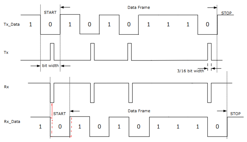
Relationship between IrDA signal and UART signal
The following table details the pulse duration specifications at various signaling rates in Serial Infrared (SIR) mode supported by this chip. The maximum transmission rate is 115.2 kbps.
Signaling rate |
Modulation |
Rate tolerance (%) |
Pulse duration (min.) |
Pulse duration (typ.) |
Pulse duration (max.) |
|---|---|---|---|---|---|
2.4 kbps |
RZI |
±0.87 |
1.41 us |
78.13 us |
88.85 us |
9.6 kbps |
RZI |
±0.87 |
1.41 us |
19.53 us |
22.13 us |
19.2 kbps |
RZI |
±0.87 |
1.41 us |
9.77 us |
11.07 us |
38.4 kbps |
RZI |
±0.87 |
1.41 us |
4.88 us |
5.96 us |
57.6 kbps |
RZI |
±0.87 |
1.41 us |
3.26 us |
4.34 us |
115.2 kbps |
RZI |
±0.87 |
1.41 us |
1.63 us |
2.23 us |
Interrupt
The UART supports both individual and combined interrupt requests, which can both be masked as well. The combined interrupt request is the ORed result of all other UART interrupts after masking. The system designer has the choice of routing individual interrupt requests or only the combined interrupt request to the Interrupt Controller. The UART interrupts are described as follows:
Received Data Available Interrupt (ERBFI) - Set when Rx FIFO Trigger Level is reached or Rx FIFO is full. Rx FIFO Trigger Level can be configured by software in FIFO Control Register (FCR, bit[7:6]), defines the level of receiver FIFO entries at which an interrupt is generated. This interrupt is cleared by hardware when Rx FIFO entries fall below the trigger level. Bit RXFIFO_INT in Line Status Register (LSR, bit8) will be set when this interrupt happens.
Transmitter FIFO Empty Interrupt (ETBEI) - Set when the transmit FIFO is empty. This interrupt is cleared by hardware when data is written into the Tx FIFO buffer. Bit TX_EMPTY in Line Status Register (LSR, bit5) will be set when this interrupt happens.
Receiver Line Status Interrupt (ELSI) - Set when overrun, parity error, framing error or break condition is detected on the Rx line. This interrupt remains set until the Receiver Line Status Interrupt Clear Flag (RLSICF) in Interrupt Clear Register (ICR) is set by the user. Bit OVR_ERR (LSR, bit1), bit PAR_ERR (LSR, bit2), bit FRM_ERR (LSR, bit3) and bit BREAK_INT (LSR, bit4) will be set accordingly when detecting overrun, parity error, framing error and break condition on the Rx line. Bit RXFIFO_ERR (LSR, bit7) will be set when any of the events mentioned before happens. Writing
1to RLSICF will also clear RXFIFO_ERR status.Modem Status Interrupt (EDSSI) - Set when a falling edge is detected on CTS line with hardware auto flow control enabled. This interrupt remains set until the Modem Interrupt Clear Flag (MICF) in ICR is set by the user. Bit MODEM_INT (LSR, bit11) will be set when this interrupt happens.
Rx Path Monitor Done Interrupt (EMDI) - Set when monitor process is over with Rx path monitor function enabled. This interrupt remains set until the Monitor Done Interrupt Clear Flag (MDICF) in ICR is set by the user. Bit MONITOR_DONE_INT (LSR, bit10) will be set when this interrupt happens.
Rx Timeout Interrupt (ETOI) - Set when no character has been input to the Rx FIFO or read from it before time expires when there is at least one character in the Rx FIFO. This interrupt remains set until the Timeout Interrupt Clear Flag (TOICF) in ICR is set by the user. Bit TIMEOUT_INT (LSR, bit9) will be set when this interrupt happens.
RXFIFO Empty Timeout Interrupt (ERETI) - Set when Rx FIFO stays empty until time expires. This interrupt remains set until the RXFIFO Empty Timeout Interrupt Clear Flag (RETICF) in ICR is set by the user. Bit RE_TIMEOUT_INT (LSR, bit13) will be set when this interrupt happens.
Rx Noise Detected Interrupt (ERXNDI) - Set when Rx debouncer has detected noise. This interrupt remains set until the Rx Noise Detected Interrupt Clear Flag (RXNDICF) in ICR is set by the user. Bit RXND_INT (LSR, bit12) will be set when this interrupt happens.
Rx Timeout Interrupt (ETOI) is supported and time can be set in Rx Path Control Register (RX_PATH_CTRL, bit[31:16]).
RXFIFO Empty Timeout Interrupt (ERETI) is not supported.
Rx Timeout Interrupt (ETOI) is supported and time can be set in Rx Path Control Register (RX_PATH_CTRL, bit[31:16]).
RXFIFO Empty Timeout Interrupt (ERETI) is not supported.
Rx Timeout Interrupt (ETOI) is supported and time can be set in Rx Path Control Register (RX_PATH_CTRL, bit[31:16]).
RXFIFO Empty Timeout Interrupt (ERETI) is not supported.
Rx Timeout Interrupt (ETOI) is supported and time can be set in Rx Path Control Register (RX_PATH_CTRL, bit[31:16]).
RXFIFO Empty Timeout Interrupt (ERETI) is not supported.
Rx Timeout Interrupt (ETOI) is supported and time can be set in Rx Path Control Register (RX_PATH_CTRL, bit[31:16]).
RXFIFO Empty Timeout Interrupt (ERETI) is not supported.
Rx Timeout Interrupt (ETOI) is supported and time can be set in Rx Path Control Register (RX_PATH_CTRL, bit[31:16]).
RXFIFO Empty Timeout Interrupt (ERETI) is not supported.
Rx Timeout Interrupt (ETOI) is supported and time can be set in Rx Path Control Register (RX_PATH_CTRL, bit[31:16]).
RXFIFO Empty Timeout Interrupt (ERETI) is supported and time can be set in RXFIFO Empty Interrupt Timeout Threshold Register (TH_RETI, bit[27:0]).
Rx Timeout Interrupt (ETOI) is supported and time can be set in Rx Timeout Threshold Register (RXTO_THRS, bit[27:0]).
RXFIFO Empty Timeout Interrupt (ERETI) is supported and time can be set in Rx Timeout Threshold Register (RXTO_THRS, bit[27:0]).
Auto Flow Control
It is possible to control the serial UART data flow between 2 devices by using the nCTS input and the nRTS output. The following figure shows how to connect the two devices in auto flow control mode.
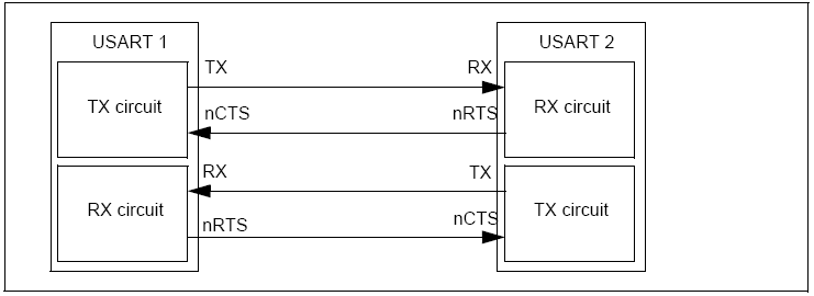
When auto flow control mode is enabled, if input nCTS is deasserted in Tx idle state, the transmission does not occur; if input nCTS is deasserted during transmission, the current transmission is completed before the transmitter stops. When Rx FIFO is almost full, nRTS is deasserted to inform peer device to stop transmission at the end of current transmission.
The UART can be configured to work under hardware data flow control, which is composed of Auto RTS and Auto CTS. Enable Auto Flow Control by asserting AFE bit in the Modem Control Register (MCR, bit5). Auto RTS and Auto CTS are described as follows:
Auto RTS
Auto RTS becomes active when the following occurs:
Auto Flow Control is enabled (MCR[5] is set)
RTS output is enabled (MCR[1] is set)
FIFOs are enabled (FCR[0] is set)
When Auto RTS is enabled (active), RTS signal is forced inactive (high) automatically once the receiver FIFO reaches Rx_FIFO_Trigger_Level.
The optional receiver FIFO threshold values are 1, 1/4, 1/2, and 2 less than full. Since one additional character may be transmitted to the UART after RTS has become inactive as shown in Auto RTS timing (due to data in the other UART has already entered the transmitter block before it recognizes the deassertion of RTS), setting the threshold to 2 less than full makes the best use of the FIFO with a safety zone of one character.
Once the receiver FIFO becomes completely empty by reading the Receiver Buffer Register (RBR_OR_THR), RTS becomes active (low) again, signaling the other UART to continue sending data.
Once the receiver FIFO becomes completely empty by reading the Receiver Buffer Register (RBR_OR_THR), RTS becomes active (low) again, signaling the other UART to continue sending data.
Once the receiver FIFO becomes completely empty by reading the Receiver Buffer Register (RBR_OR_THR), RTS becomes active (low) again, signaling the other UART to continue sending data.
Once the receiver FIFO becomes completely empty by reading the Receiver Buffer Register (RBR_OR_THR), RTS becomes active (low) again, signaling the other UART to continue sending data.
Once the receiver FIFO becomes completely empty by reading the Receiver Buffer Register (RBR_OR_THR), RTS becomes active (low) again, signaling the other UART to continue sending data.
Once the receiver FIFO becomes completely empty by reading the Receiver Buffer Register (RBR_OR_THR), RTS becomes active (low) again, signaling the other UART to continue sending data.
Once the receiver FIFO level falls below (Rx_FIFO_Trigger_Level - 2) by reading the Receiver Buffer Register (RBR_OR_THR), RTS becomes active (low) again, signaling the other UART to continue sending data.
Once the receiver FIFO level falls below (Rx_FIFO_Trigger_Level - 2) by reading the Receiver Buffer Register (RBR_OR_THR), RTS becomes active (low) again, signaling the other UART to continue sending data.
It is important to note that even if everything else is selected and the correct MCR bits are set, if the FIFOs are disabled through FCR bit0, Auto Flow Control is also disabled. When Auto RTS is not implemented or disabled, RTS is controlled solely by MCR bit1. The following figure shows a timing diagram of Auto RTS operation.

Auto RTS timing
Auto CTS
Auto CTS becomes active when the following occurs:
Auto Flow Control is enabled (MCR[5] is set)
FIFOs are enabled (FCR[0] is set)
SIR mode is disabled (MISCR[0] bit is cleared)
When Auto CTS is enabled (active), the UART transmitter is disabled automatically once the CTS input becomes inactive (high). This prevents overflowing the FIFO of the receiving device (e.g. another UART). If the CTS input is not deasserted before the middle of the last stop bit, another character is transmitted before the transmitter is disabled. While the transmitter is disabled, the transmitter FIFO can still be written to, and even overflowed.
The UART status register can be read to check if the transmit FIFO is full (LSR bit6 = 0).
When using the FIFO full status, the software can poll this before each write to the transmitter FIFO. When the CTS input becomes active (low) again, transmission resumes. It is important to note that even if everything else is selected, if the FIFOs are disabled via FCR[0], Auto Flow Control is also disabled. When Auto CTS is not implemented or disabled, the transmitter is unaffected by CTS. A Timing Diagram showing Auto CTS operation can be seen below:

Auto CTS timing
Note
Due to pin count limitations on the SoC, not all UART interfaces support RTS/CTS pins. Please refer to the specific chip datasheet for more pin details. Auto flow control is not supported on UART ports lacking RTS/CTS pins.
DMA Flow Control
The GDMA always acts as the DMA flow controller for UART Tx. However, for UART Rx, either the GDMA or the UART can serve as the DMA flow controller. Note that only the Rx DMA mode is illustrated in this section.
GDMA as DMA flow controller
When the GDMA acts as the DMA flow controller (as shown below), it sets the expected block length before a block transfer begins, and terminates the transfer when the Rx length equals the block length. The rx_dma_req signal is asserted when the data size in the Rx FIFO is greater than or equal to the burst size, and the rx_dma_single signal is asserted when the Rx FIFO is not empty. The rx_dma_ack signal is asserted after the data phase of the last AHB transfer (single or burst) in the current transaction is completed. When the GDMA is the flow controller, the rx_dma_last signal is not sampled and is ignored.

GDMA as DMA flow controller
When the GDMA acts as the DMA flow controller (as shown below), it sets the expected block length before a block transfer begins, and terminates the transfer when the Rx length equals the block length. The rx_dma_req signal is asserted when the data size in the Rx FIFO is greater than or equal to the burst size, and the rx_dma_single signal is asserted when the Rx FIFO is not empty. The rx_dma_ack signal is asserted after the data phase of the last AHB transfer (single or burst) in the current transaction is completed. When the GDMA is the flow controller, the rx_dma_last signal is not sampled and is ignored.
GDMA as DMA flow controller
When the GDMA acts as the DMA flow controller (as shown below), it sets the expected block length before a block transfer begins, and terminates the transfer when the Rx length equals the block length. The rx_dma_req signal is asserted when the data size in the Rx FIFO is greater than or equal to the burst size, and the rx_dma_single signal is asserted when the Rx FIFO is not empty. The rx_dma_ack signal is asserted after the data phase of the last AHB transfer (single or burst) in the current transaction is completed. When the GDMA is the flow controller, the rx_dma_last signal is not sampled and is ignored.
GDMA as DMA flow controller
When the GDMA acts as the DMA flow controller (as shown below), it sets the expected block length before a block transfer begins, and terminates the transfer when the Rx length equals the block length. The rx_dma_req signal is asserted when the data size in the Rx FIFO is greater than or equal to the burst size, and the rx_dma_single signal is asserted when the Rx FIFO is not empty. The rx_dma_ack signal is asserted after the data phase of the last AHB transfer (single or burst) in the current transaction is completed. When the GDMA is the flow controller, the rx_dma_last signal is not sampled and is ignored.
GDMA as DMA flow controller
When the GDMA acts as the DMA flow controller (as shown below), it sets the expected block length before a block transfer begins, and terminates the transfer when the Rx length equals the block length. The rx_dma_req signal is asserted when the data size in the Rx FIFO is greater than or equal to the burst size, and the rx_dma_single signal is asserted when the Rx FIFO is not empty. The rx_dma_ack signal is asserted after the data phase of the last AHB transfer (single or burst) in the current transaction is completed. When the GDMA is the flow controller, the rx_dma_last signal is not sampled and is ignored.
GDMA as DMA flow controller
When the GDMA acts as the DMA flow controller (as shown below), it sets the expected block length before a block transfer begins, and terminates the transfer when the Rx length equals the block length. The rx_dma_req signal is asserted when the data size in the Rx FIFO is greater than or equal to the burst size, and the rx_dma_single signal is asserted when the Rx FIFO is not empty. The rx_dma_ack signal is asserted after the data phase of the last AHB transfer (single or burst) in the current transaction is completed. When the GDMA is the flow controller, the rx_dma_last signal is not sampled and is ignored.
GDMA as DMA flow controller
When the GDMA acts as the DMA flow controller (as shown below), it sets the expected block length before a block transfer begins, and terminates the transfer when the Rx length equals the block length. The rx_dma_req signal is asserted when the data size in the Rx FIFO is greater than or equal to the burst size, and the rx_dma_single signal is asserted when the Rx FIFO is not empty. The rx_dma_ack signal is asserted after the data phase of the last AHB transfer (single or burst) in the current transaction is completed. When the GDMA is the flow controller, the rx_dma_last signal is not sampled and is ignored.
GDMA as DMA flow controller
Specifically, when the data transfer is unpredictable (e.g., the amount of Rx data is unknown), it is recommended to set the GDMA as the flow controller:
The UART Rx burst size and the GDMA burst transaction size should both be set to 1. The GDMA block transfer size should be set to a value larger than the expected amount, or directly to 65535 (the maximum value). Additionally, the RXFIFO Empty Timeout Interrupt (ERETI) should be enabled to notify that the transaction has been halted for a certain period.
Once the RXFIFO Empty Timeout Interrupt (ERETI) is triggered, RXDMA_EN will be cleared automatically by hardware, and a DMA request will not be asserted even if new data enters the Rx FIFO. The number of bytes read from the Rx FIFO by the DMA can be obtained from the register UART_RX_BYTE_CNT. If new data arrives after the interrupt occurs, the user can manually read the remaining data in the Rx FIFO. The user should also disable the DMA.
When the GDMA acts as the DMA flow controller (as shown below), it sets the expected block length before a block transfer begins, and terminates the transfer when the Rx length equals the block length. The rx_dma_req signal is asserted when the data size in the Rx FIFO is greater than or equal to the burst size, and the rx_dma_single signal is asserted when the Rx FIFO is not empty. The rx_dma_ack signal is asserted after the data phase of the last AHB transfer (single or burst) in the current transaction is completed. When the GDMA is the flow controller, the rx_dma_last signal is not sampled and is ignored.
GDMA as DMA flow controller
Specifically, when the data transfer is unpredictable (e.g., the amount of Rx data is unknown), it is recommended to set the GDMA as the flow controller:
The UART Rx burst size and the GDMA burst transaction size should both be set to 1. The GDMA block transfer size should be set to a value larger than the expected amount, or directly to 65535 (the maximum value). Additionally, the RXFIFO Empty Timeout Interrupt (ERETI) should be enabled to notify that the transaction has been halted for a certain period.
Once the RXFIFO Empty Timeout Interrupt (ERETI) is triggered, RXDMA_EN will be cleared automatically by hardware, and a DMA request will not be asserted even if new data enters the Rx FIFO. The number of bytes read from the Rx FIFO by the DMA can be obtained from the register UART_RX_BYTE_CNT. If new data arrives after the interrupt occurs, the user can manually read the remaining data in the Rx FIFO. The user should also disable the DMA.
UART as DMA flow controller
When the UART acts as the DMA flow controller (as shown below), UART asserts the rx_dma_last signal to terminate block transfer when UART has received the whole packet. The finish flag is defined as: no new Rx character arrives within UART_RX_BYTE_CNT time in register UART_RX_PATH_CTRL after the last Rx character.
When the UART acts as the DMA flow controller (as shown below), UART asserts the rx_dma_last signal to terminate block transfer when UART has received the whole packet. The finish flag is defined as: no new Rx character arrives within UART_RX_BYTE_CNT time in register UART_RX_PATH_CTRL after the last Rx character.
When the UART acts as the DMA flow controller (as shown below), UART asserts the rx_dma_last signal to terminate block transfer when UART has received the whole packet. The finish flag is defined as: no new Rx character arrives within UART_RX_BYTE_CNT time in register UART_RX_PATH_CTRL after the last Rx character.
When the UART acts as the DMA flow controller (as shown below), UART asserts the rx_dma_last signal to terminate block transfer when UART has received the whole packet. The finish flag is defined as: no new Rx character arrives within UART_RX_BYTE_CNT time in register UART_RX_PATH_CTRL after the last Rx character.
When the UART acts as the DMA flow controller (as shown below), UART asserts the rx_dma_last signal to terminate block transfer when UART has received the whole packet. The finish flag is defined as: no new Rx character arrives within UART_RX_BYTE_CNT time in register UART_RX_PATH_CTRL after the last Rx character.
When the UART acts as the DMA flow controller (as shown below), UART asserts the rx_dma_last signal to terminate block transfer when UART has received the whole packet. The finish flag is defined as: no new Rx character arrives within UART_RX_BYTE_CNT time in register UART_RX_PATH_CTRL after the last Rx character.
When the UART acts as the DMA flow controller (as shown below), UART asserts the rx_dma_last signal to terminate block transfer when UART has received the whole packet. The finish flag is defined as: no new Rx character arrives within UART_RX_BYTE_CNT time in register UART_RX_PATH_CTRL after the last Rx character.
When the UART acts as the DMA flow controller (as shown below), UART asserts the rx_dma_last signal to terminate block transfer when UART has received the whole packet. The finish flag is defined as: no new Rx character arrives within UART_R_RXTO_THRS time in register UART_RXTO_THRS after the last Rx character, or the total number of bytes received via UART reaches the configured limit of UART_RXDMA_MAX_LEN, which defines the maximum byte count for the reception.
Before rx_dma_req signal is asserted, the amount of data to be transferred is calculated and the following actions will be performed:
If the amount of data to be transferred is less than the DMA Rx burst size, all remaining data will be transferred in a single DMA transaction by asserting rx_dma_single signal. When there is only one byte of data remaining to be transferred, rx_dma_last signal will be asserted and the final byte will be transferred to the destination memory by DMA.
Remaining Rx byte count can be checked in UART_RXDMA_REMAIN_LEN register during transfer. It will be reset to the value of UART_RXDMA_MAX_LEN when DMA transmission is completed (rx_dma_last=1) or rx_dma_en is disabled.

UART as DMA flow controller
The following figure illustrates the DMA interface timing diagram when the total Rx packet length is not a multiple of the burst transaction size. T1 and T2 are burst transfer, T3 and T4 are single transfer. T2 is the last burst transfer of block transfer. After timeout, there are two entries in Rx FIFO, which is less than burst transaction transfer size. Then UART starts two single transfers (T3 and T4) to finish block transfer. rx_dma_last is transferred to GDMA together with the last rx_dma_req. In this case, there may be several single transfers after timeout.

DMA interface timing diagram (block size is not multiple of burst transaction size)
The following figure illustrates the DMA interface timing diagram when the total Rx packet length is a multiple of the burst transaction size. Block transfer is actually done after the last burst transfer of T2. However, UART cannot determine the end of block transfer until timeout happens. In T3, UART starts a dummy single last transfer to inform GDMA, and sets DUMMY_FLAG in the MISCR register for software judgment at the same time. The dummy data can be configured by DUMMY_DATA in MISCR.

DMA interface timing diagram (block size is multiple of burst transaction size)
Low Power Rx
The clock structure of Rx path for UART0, UART1, UART2_BT and LOGUART is similar. The following figure is the clock structure of UARTx Rx path, where x can be from 0 to 2. The cksl_uart signal in REG_CKSL_GRP0 register decides the clock for UARTx Rx path.

In the low-power state:
The OSC2M clock (divided from OSC4M) is supported as the UART Rx clock to wake up the system;
XTAL40M is directly gated. If the XTAL40M clock is used as the UART Rx clock, the system cannot be woken up.
Note
To wake up the system via UART, set PMC_BIT_PST_SLEP_ERCK to 1 to ensure cke_uartx is 1 during sleep.
The clock structure of Rx path for UART0, UART1, UART2, UART3_BT and LOGUART is similar. The following figure is the clock structure of UARTx Rx path, where x can be from 0 to 3. The cksl_uart signal in REG_CKSL_GRP0 register decides the clock for UARTx Rx path.
After the system enters the low-power state, data can be sent to the UART to wake up the system via the UART interrupt.
In the low-power state, XTAL40M/OSC2M clocks can both be selected as the UART Rx clock, allowing the system to be woken up.
Note
If XTAL40M is selected as the clock source, PMC_MASK_PST_SLEP_XMD must be set to 0x3 (normal);
The clock structure of Rx path for UART0, UART1, UART2, UART3_BT and LOGUART is similar. The following figure is the clock structure of UARTx Rx path, where x can be from 0 to 3. The cksl_uart signal in REG_CKSL_GRP0 register decides the clock for UARTx Rx path.
After the system enters the low-power state, data can be sent to the UART to wake up the system via the UART interrupt.
In the low-power state, XTAL40M/OSC2M clocks can both be selected as the UART Rx clock, allowing the system to be woken up.
Note
If XTAL40M is selected as the clock source, PMC_MASK_PST_SLEP_XMD must be set to 0x3 (normal);
The clock structure of Rx path for UART0, UART1, UART2, UART3_BT and LOGUART is similar. The following figure is the clock structure of UARTx Rx path, where x can be from 0 to 3. The cksl_uart signal in REG_CKSL_GRP0 register decides the clock for UARTx Rx path.
After the system enters the low-power state, data can be sent to the UART to wake up the system via the UART interrupt.
In the low-power state, XTAL40M/OSC2M clocks can both be selected as the UART Rx clock, allowing the system to be woken up.
Note
If XTAL40M is selected as the clock source, PMC_MASK_PST_SLEP_XMD must be set to 0x3 (normal);
The clock structure of Rx path for UART0, UART1, UART2, UART3_BT and LOGUART is similar. The following figure is the clock structure of UARTx Rx path, where x can be from 0 to 3. The cksl_uart signal in REG_CKSL_GRP0 register decides the clock for UARTx Rx path.
After the system enters the low-power state, data can be sent to the UART to wake up the system via the UART interrupt.
In the low-power state, XTAL40M/OSC2M clocks can both be selected as the UART Rx clock, allowing the system to be woken up.
Note
If XTAL40M is selected as the clock source, PMC_MASK_PST_SLEP_XMD must be set to 0x3 (normal);
The clock structure of Rx path for UART0, UART1, UART2 and LOGUART is similar. The following figure is the clock structure of UARTx Rx path, where x can be from 0 to 2. The cksl_uart signal and cksl_uart2m signal in REG_CKSL_GRP0 register decide the clock for UARTx Rx path. Rx clock of UART3_BT is always XTAL40M.
After the system enters the low-power state, data can be sent to the UART to wake up the system via the UART interrupt.
In the low-power state, XTAL40M/OSC2M clocks can both be selected as the UART Rx clock, allowing the system to be woken up.
Note
If XTAL40M is selected as the clock source, PMC_MASK_PST_SLEP_XMD must be set to 0x3 (normal);
If OSC2M is selected as the clock source, PMC_BIT_PST_SLEP_ERCK must be set to 1.
The clock structure of Rx path for UART0, UART1, UART2, UART3_BT and LOGUART is similar. The following figure is the clock structure of UARTx Rx path, where x can be from 0 to 3. The cksl_uart signal in REG_CKSL_GRP1 register decides the clock for UARTx Rx path.

After the system enters the low-power state, data can be sent to the UART to wake up the system via the UART interrupt.
In the low-power state, XTAL40M/OSC2M clocks can both be selected as the UART Rx clock, allowing the system to be woken up.
Note
To use XTAL40M as the UART Rx clock, set keep_osc4m_on and sleep_to_08V in ps_config to TRUE in ameba_sleepcfg.c, and set xtal_mode_in_sleep to a proper value (e.g., XTAL_LPS_With_40M).
To use OSC2M as the UART Rx clock, set keep_osc4m_on in ps_config to TRUE in ameba_sleepcfg.c.
The clock structure of Rx path for UART0, UART1, UART2 and LOGUART is similar. The following figure is the clock structure of UARTx Rx path, where x can be from 0 to 2. The cksl_uart signal in REG_CKSL_GRP1 register decides the clock for UARTx Rx path.
After the system enters the low-power state, data can be sent to the UART to wake up the system via the UART interrupt.
In the low-power state, XTAL40M/OSC2M clocks can both be selected as the UART Rx clock, allowing the system to be woken up.
Note
To use XTAL40M as the UART Rx clock, set keep_osc4m_on and sleep_to_08V in ps_config to TRUE in ameba_sleepcfg.c, and set xtal_mode_in_sleep to a proper value (e.g., XTAL_LPS_With_40M).
To use OSC2M as the UART Rx clock, set keep_osc4m_on in ps_config to TRUE in ameba_sleepcfg.c.
Rx Path Monitor Function
UART Rx path supports fractional baud rate generator and it can monitor and eliminate Rx baud rate error and own frequency drift. Fractional baud rate and baud rate monitor cannot be used simultaneously.
When the monitor function is enabled (UART_MON_BAUD_CTRL, bit[0]), software sets the original cycle number according to default baud rate, then Rx circuit counts total cycle number M of N bit durations, so the average cycle number per bit duration L = M/N, the maximum value of N is 127. Hardware will replace the original cycle number per bit with the newly calculated value L, thus baud rate error from peer device and own frequency deviation can be almost eliminated.
Note
When Rx path monitor function is enabled, baud rate should not be greater than 1/17 of current LP clock frequency.
UART Rx Debounce
UART supports Rx debounce to filter glitches in Rx signals. The function can be enabled by asserting DBNC_FEN bit in UART_RXDBCR register. Rx debounce clock source is the same as the Rx clock source, which can be XTAL 40MHz or OSC 2MHz. DBNC_CYC field in UART_RXDBCR register is set to debounce Rx signals with different glitches.
When DBNC_FEN bit in UART_RXDBCR register is asserted, glitches shorter than DBNC_CYC debounce clock cycles will be filtered as shown below. Meanwhile, delay will be introduced to Rx signal for (DBNC_CYC + 2) debounce clock cycles.
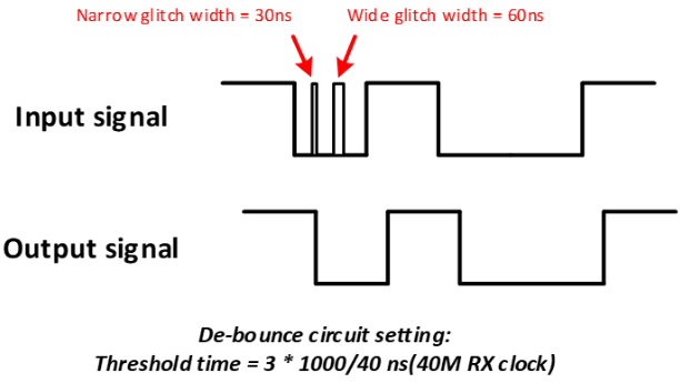
UART Rx debounce
UART CTS Debounce
CTS is also a UART input signal, which is as susceptible to line noise as the Rx signal. UART supports CTS debounce to filter glitches on the CTS input, following the same mechanism as UART Rx Debounce.
Not supported.
Not supported.
Not supported.
Not supported.
Not supported.
Not supported.
Not supported.
Not supported.
UARTx_BT Used as Normal UART
UART interfaces can be configured to connect internally to the Bluetooth (BT) module for communication. Alternatively, they can be configured as standard UARTs to communicate with external devices.
Note
This feature is not supported by all ICs.
The relevant UART controller can only be configured as normal UART when the BT function is not in use.
UART2_BT is used for internal BT UART by default.
For normal UART usage, set the relevant register described below.
Name: REG_LSYS_BT_CTRL0
Size: 32 bits
Base Address:
0x41008000Address offset:
0x280Read/write access: read/write
Bit |
Name |
Access |
Reset |
Description |
|---|---|---|---|---|
19 |
BT_USE_EXT_UART |
R/W |
0x0 |
|
UART3_BT is used for internal BT UART by default.
For normal UART usage, set the relevant register described below.
Name: REG_LSYS_BT_CTRL0
Size: 32 bits
Base Address:
0x4100C000Address offset:
0x280Read/write access: read/write
Bit |
Name |
Access |
Reset |
Description |
|---|---|---|---|---|
19 |
BT_USE_EXT_UART |
R/W |
0x0 |
|
UART3_BT is used for internal BT UART by default.
For normal UART usage, set the relevant register described below.
Name: REG_LSYS_BT_CTRL0
Size: 32 bits
Base Address:
0x4100C000Address offset:
0x280Read/write access: read/write
Bit |
Name |
Access |
Reset |
Description |
|---|---|---|---|---|
19 |
BT_USE_EXT_UART |
R/W |
0x0 |
|
UART3_BT is used for internal BT UART by default.
For normal UART usage, set the relevant register described below.
Name: REG_LSYS_BT_CTRL0
Size: 32 bits
Base Address:
0x4100C000Address offset:
0x280Read/write access: read/write
Bit |
Name |
Access |
Reset |
Description |
|---|---|---|---|---|
19 |
BT_USE_EXT_UART |
R/W |
0x0 |
|
UART3_BT is used for internal BT UART by default.
For normal UART usage, set the relevant register described below.
Name: REG_LSYS_BT_CTRL0
Size: 32 bits
Base Address:
0x4100C000Address offset:
0x280Read/write access: read/write
Bit |
Name |
Access |
Reset |
Description |
|---|---|---|---|---|
19 |
BT_USE_EXT_UART |
R/W |
0x0 |
|
UARTx_BT is not supported.
UART3_BT is used for internal BT UART by default.
For normal UART usage, set the relevant register described below.
Name: REG_LSYS_BT_CTRL0
Size: 32 bits
Base Address:
0x4080A000Address offset:
0x2B8Read/write access: read/write
Bit |
Name |
Access |
Reset |
Description |
|---|---|---|---|---|
19 |
BT_USE_EXT_UART |
R/W |
0x0 |
|
UARTx_BT is not supported.

