The Real-Time Clock (RTC) is an independent BCD-format timer/counter. As a core low-power timing peripheral of the chip, it provides continuous timekeeping, precise timing, and security protection capabilities. It can maintain uninterrupted operation across all chip operating states, meeting the needs of embedded devices for time management, low-power wakeup, and timed triggering.
The RTC of the Ameba series SOC implements only time and date counting; calendar and year management are handled by software. It supports a digital calibration feature for time correction, is equipped with backup registers that retain data even in deep sleep mode, and supports daylight saving time compensation, scheduled wakeup, and periodic wakeup functions.
The RTC module uses SDM32K as the clock source, generates a time base through two-stage frequency division and calibration, and provides time counting, alarm, and multiple clock output functions.
Clock Chain
The input clock RTCCLK(32.768kHz) first passes through an asynchronous prescaler (division factor 128), outputting a 256 Hz clk_apre signal.
clk_apre then enters a synchronous prescaler with calibration capability (division factor 256), ultimately generating a 1 Hz clk_spre signal as the reference clock for the time counter.
The synchronous prescaler supports frequency calibration, fine-tuning the output frequency through the formula (-1)^DCS*DC/((PREDIV_S+1)*(CALP+1)*60) to compensate for crystal oscillator errors.
Time Counting and Alarm
The time counter uses clk_spre(1Hz) as the clock, incrementing in day:hh:mm:ss format to maintain system time.
The alarm module supports configuring alarm time in day:hh:mm:ss format. When the time counter matches the alarm register value, an alarm_out signal is output, which can be used to trigger an interrupt or wakeup event.
Output Selection
The final output RTC_OUT of the RTC module is configured by OSEL[1:0], which can output clk_spre(1Hz), clk_apre(256Hz), or alarm_out signal to meet clock or event output requirements in different application scenarios.
VDH_RTC is the independent power supply pin for the RTC_IO module, available only in certain packages. Users can design a separate power supply circuit for this pin. When the main chip power is on, the RTC will periodically and automatically back up to RTC_IO. When the main chip power is off, RTC_IO will continue counting using the OSC131K clock domain. After the main system power is restored, SW processing time is required to recover and maintain system time continuity. During the power-off operation of the main system, the RTC timing accuracy is limited by the inherent accuracy of the OSC131K clock; this oscillator is calibrated once by software during power-on, but due to its process characteristics, the actual timing error during power-off operation may be higher than the nominal value at the time of calibration.
RTC_IO
Overview
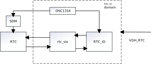
VDH_RTC can independently power the OSC131K and RTC_IO circuits to continue timekeeping when the system main power is off. RTC_IO has an internal memory to store time data obtained from the RTC, as well as a counter. RTC_IO periodically reads RTC time data and saves it to the RTC_IO module’s memory, while also resetting the counter.
When RTC_IO detects a main power loss, it stops reading RTC time and continues timekeeping using the internal counter. When the system powers on again, SW needs to read back the RTC time before power-off and the counter value to restore the system RTC time.
The RTC domain diagram is shown in the following figure.
Features
rtc_sio transmits RTC time data to the RTC_IO module in the RTC module at an interval of 1/256s.
The RTC_IO module retains RTC time data and count during power-off.
The OSC32K calibration value LDO_RCAL can be retained in the RTC_IO domain to maintain the OSC32K calibration function during power-off.
Operation Flow
To shift LDO_RCAL into RTC_IO and shift out time data from RTC_IO, perform the configuration steps illustrated in the following table.
Step
What to do
How to do
1
Manually put RTC_IO into rtc_mode (optional)
Write 2’d2 to register rtc_io_ctrl[1:0]
2
Acquire LDO_RCAL[5:0] value
Read register LDO_BASE-> LDO_32K_OSC_CTRL[5:0]
3
Prepare data into the register that will be shifted into RTC_IO
Write step 2’s value to register rtc_io_test_din[63:58]
4
Enter MODE_SHIFT_ENABLE mode to start shift operation
Write 2’d1 to register rtc_io_ctrl[1:0]
5
Wait some time for rtc_sio to send command to RTC_IO
Wait 15ms
6
Read the stored time data and counter for further processing
Read registers rtc_io_test_dout[127:0]
7
Enter MODE_SHIFT_DISABLE mode to allow HW to recover periodic update of RTC time data into shd_reg
Write 2’d0 to register rtc_io_ctrl[1:0]
8
Process the read-back time data in step 6
Acquire the time data read from rtc_io_test_dout
Parse the stored time and separate it into sec, min, hour, day and year
Parse the counter during power-off period
Calculate new time and set it to the device
To calculate the new time, the following formula can be referenced:
However, some complex situations need to be taken into consideration, such as seconds carrying over to minutes, minutes carrying over to hours, leap year, etc.
Note
The command that rtc_sio sends to RTC_IO in step 4 takes 5.78ms when osc131k has no frequency deviation.
If the RTC module initializes the time format in 12-hour format, the RTC_IO module will convert it to 24-hour format and store it. Therefore, when parsing the respective time fields and calculating the new time, this format conversion needs to be considered.
Registers
Name
Address
Width
Description
REG_AON_RTC_IO_CTRL
0x41008048
32 bits
0x41008048[4]: RTC IO mode flag (Read Only)
1: RTC IO domain enabled
0: Disabled (default)
0x41008048[1:0]: RTC IO control mode (R/W)
0: Shift disable
1: Shift enable
2: RTC mode (once enable , it can’t be disabled)
rtc_io_test_din
0x420080E0
128 bits
0x410080E0[63:58]: LDO_RCAL value
receive LDO_RCAL value written by software
rtc_io_test_dout
0x410080C0
128 bits
0x410080C0[33:0]: Binary storage for year/day/hour/minute/second (e.g.: 33sec saved as sec[5:0]=6’b10_0001)
sec: 6’b0; 0x4100_80C0[5:0]
min: 6’b0; 0x4100_80C0[11:6]
hour: 5’b0; 0x4100_80C0[16:12]
day: 9’b0; 0x4100_80C0[25:17]
year: 8’b0; 0x4100_80C0[33:26]
0x410080C0 [83:42]: Counter during power-off period, the counter clock is OSC131K.
RTL8720E:
System-powered, without independent power supply.
RTL8710E:
System-powered, without independent power supply.
RTL8726E:
System-powered, without independent power supply.
RTL8713E:
System-powered, without independent power supply.
RTL8730E:
System-powered, without independent power supply.
RTL8721F:
VDH_RTC is a dedicated power supply pin for the RTC module, available only in certain packages. Users can design an independent power supply circuit for this pin. When the main system power is off, the RTC automatically switches to the OSC131K/4 clock to continue timekeeping. When the main system power is restored, it automatically switches back to the SDM32K clock to continue timekeeping, maintaining system time continuity. During main system power-off operation, RTC timekeeping accuracy is limited by the inherent accuracy of the OSC131K clock. This oscillator is calibrated once by software during power-up, but due to its process characteristics, the actual timekeeping error during main system power-off operation will be higher than the nominal value at calibration.