Introduction
The Dot-Matrix LED driver chips typically communicate with the host controller via synchronous serial interfaces or proprietary protocols, requiring the host to emulate the corresponding protocol for data exchange. Compared to software emulation, a dedicated hardware IP can apply specialized handling within the reset domain, ensuring that display output remains unaffected even when an exception occurs during a display update.
The Dot-Matrix LED Controller is an LEDC driver module that supports a pseudo I2C protocol. It features unidirectional data transmission without requiring slave acknowledgement or address confirmation, and can transfer up to 127 bytes of data in a single transaction.
Features
Two-wire I2C serial interface: SCL and SDA
Start signal and stop signal generation supported
Supported transfer rates: 100 Kbps, 400 Kbps, and 1 Mbps
Pseudo I2C mode:
Maximum transfer size: 127 bytes
Master-only mode
No ACK/NACK signals required
Power and reset characteristics:
Continues operating during software reset, watchdog reset, and system reset
Block Diagram
The block diagram of the Dot-Matrix LED Controller is shown below:
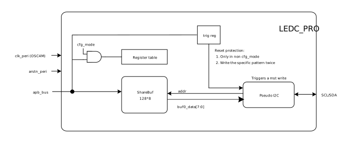
Register Table: stores control parameters and status information
ShareBuf: 128x8-bit shared buffer that caches data to be transferred
Trig Reg: trigger register; writing a specific sequence triggers a pseudo I2C master write operation
Pseudo I2C: pseudo I2C controller that reads data from the shared buffer and generates SCL/SDA signals
OSC4M: module operating clock