Functional Description
Output Timing
The sequence of logic “1” code, logic “0” code, and refresh period varies among intelligent LEDs. The basic sequence decode chart is shown in the figure.
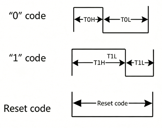
LED decode data sequence chart
In order to generate configurable LED sequence signals, LEDC counts several XTAL40MHz clock periods according to LEDC_T1H_CNT / LEDC_T1L_CNT (register 0x004[31:16]) and LEDC_T0H_CNT / LEDC_T0L_CNT (register 0x004[15:0]) of LEDC_LED_T01_TIMING_CTRL_REG. LEDC output signals are shown in the figure.

LEDC output data format when IDLE state is High
Transfer Timing
The figure below illustrates the LEDC frame output. Before sending a frame of data, a RESET is sent first to refresh the LED. ‘wait_time1’ is used to reduce the refresh rate, and can be disabled by setting LEDC_BIT_WAIT_TIME1_EN (register 0x014[31]) of LEDC_WAIT_TIME1_CTRL_REG to 0. Only the last frame of a scan may contain fewer LEDs than the total LED count.

LEDC output timing diagram of a scan
RESET: A period of time that remains LOW to refresh the LED.
Pixel: 24-bit logical ‘0’ or ‘1’ data decoded into waveforms that form a package or a pixel. LEDs bypass the low level and reshape the high level through the internal signal reshaping amplification circuit.
wait_time0: A period of LOW-level time between two pixel data. This is optional.
wait_time1: A period of LOW-level time after RESET, except for the first frame. This is optional.
Frame: The total number of LEDs. A frame starts after LEDC sends a RESET to the LED.
Scan: Includes all data packages. A scan can contain multiple frames or less than one frame. A scan starts when software configures LEDC and sets
LEDC_BIT_EN(register 0x00[0]) of LEDC_CTRL_REG to 1. The scan stops when LEDC is disabled.
LED Cascade Method
The data mode of LEDC output is based on intelligent LEDs. The typical application circuit of LEDs is shown in the figure.

LED typical application circuit
The supported RGB LEDs use auto-reshaping transmission technology. LEDC sends data in the sequence shown in the figure below, where N represents the number of LEDs driven by LEDC, and Dn represents the data received by the Nth LED.

LEDC data transfer sequence
The intelligent LED captures the first 24-bit data package from Din, reshapes the subsequent data, and outputs it from Dout. To refresh the buffered data of an LED, a RESET must be sent to the LED before new data packages are input at DI.
RGB LED Data Structure
For LEDs, the control circuit and RGB chip are integrated into a single package, forming a complete addressable pixel. Each of the three primary colors per pixel can achieve 256-level brightness display, enabling 16777216-color full-color display.
Each data input is in RGB888 format. LEDC is compatible with different data modes at both input and output ports. By default, 24-bit data is sent in GRB mode, as shown in the figure. The higher bit is transmitted first.

LEDC data MSB order of GRB
Once the LEDC input and output data modes are determined, software sets LEDC_MASK_LED_RGB_MODE (register 0x00[8:6]) of LEDC_CTRL_REG according to the table below.
RGB out mode |
Input GRB |
Input GBR |
Input RGB |
Input RBG |
Input BGR |
Input BRG |
|---|---|---|---|---|---|---|
000 |
GRB |
GBR |
RGB |
RBG |
BGR |
BRG |
001 |
GBR |
GRB |
RBG |
RGB |
BRG |
BGR |
010 |
RGB |
BGR |
GRB |
BRG |
GBR |
RBG |
011 |
BGR |
RGB |
BRG |
GRB |
RBG |
GBR |
100 |
RBG |
BRG |
GBR |
BGR |
GRB |
RGB |
101 |
BRG |
RBG |
BGR |
GBR |
RGB |
GRB |
Operation Mode
LEDC data transfer mode supports DMA mode and CPU interrupt mode, selected by setting LEDC_BIT_DMA_EN (register 0x1C[5]) of LEDC_DMA_CTRL_REG. The internal FIFO depth is 32, and the data width is 24-bit. The FIFO trigger threshold is configured through LEDC_FIFO_TRIG_LEVEL (register 0x1C[4:0]) of LEDC_DMA_CTRL_REG, with a recommended value of 7 or 15.
DMA Mode
When LEDC_BIT_DMA_EN (register 0x1C[5]) of LEDC_DMA_CTRL_REG is set to 1, LEDC enters DMA mode. In this mode, LEDC acts as the flow controller for DMA transfers. The recommended burst length is 8 or 16, and the maximum burst length is 32. When the remaining data to be transferred is greater than or equal to the burst length, and the available space of the internal FIFO is larger than the threshold set by LEDC_FIFO_TRIG_LEVEL, LEDC requests a DMA burst transfer. For each APB write, only the lower 24 bits are valid. When the remaining data to be transferred is less than the burst length and the internal FIFO is not full, LEDC requests a DMA single transfer.
CPU Mode
When LEDC_BIT_DMA_EN (register 0x1C[5]) of LEDC_DMA_CTRL_REG is set to 0, LEDC enters CPU interrupt mode. When the remaining data to be transferred is greater than 0 and the internal FIFO free space is less than the threshold set by LEDC_FIFO_TRIG_LEVEL, LEDC generates a FIFO_CPUREQ_INT in LEDC_LED_INT_STS_REG. Upon receiving this interrupt, the CPU can transfer data from memory to the LEDC FIFO through the APB bus.
LEDC Interrupts
LEDC has four interrupts: FIFO_OVERFLOW_INT, WAITDATA_TIMEOUT_INT, FIFO_CPUREQ_INT, and LEDC_TRANS_FINISH_INT. Each interrupt can be independently masked through the corresponding interrupt enable bit in LEDC_LED_INTERRUPT_CTRL_REG, and globally enabled or disabled through LEDC_BIT_GLOBAL_INT_EN (register 0x020[4]) of LEDC_LED_INTERRUPT_CTRL_REG. When FIFO_OVERFLOW_INT, WAITDATA_TIMEOUT_INT, or LEDC_TRANS_FINISH_INT is generated, the LEDC state machine enters the TRAP state, and software should set LEDC_BIT_SOFT_RESET (register 0x00[1]) of LEDC_CTRL_REG to perform a reset.
Interrupt Descriptions
The trigger conditions and clearing methods for each interrupt are described below:
FIFO overflow interrupt (
FIFO_OVERFLOW_INT) – Asserted when data written externally exceeds the maximum storage space of the LEDC FIFO. LEDC enters a data loss state and transitions to the TRAP state. This interrupt status is cleared by settingLEDC_BIT_SOFT_RESET(register 0x00[1]) of LEDC_CTRL_REG. In DMA mode, this will not occur because the FIFO threshold is set to 1/4 or 1/2 of the desired FIFO depth. LEDC, as a flow controller, sends dma_req based on the FIFO threshold, which matches the DMA source data width and destination data width. In CPU mode, care should be taken that the data to be sent is no more than the remaining FIFO space.Wait data timeout interrupt (
WAITDATA_TIMEOUT_INT) – Asserted when a data request has been sent but data was not pushed to the LEDC FIFO in time. The wait data phase includes wait_time0/1 and wait_data0/1, as shown in the figure below. If the internal FIFO of LEDC cannot receive data due to some abnormal situation, LEDC enters the wait data state. This may occur between two 24-bit data packages where (Twait_time0 + Twait_data0) >= min(LED_WAIT_DATA_TIME, RESET_TIME); or between two frames where Twait_data1 >= LED_WAIT_DATA_TIME. This interrupt status is cleared by settingLEDC_BIT_SOFT_RESET(register 0x00[1]) of LEDC_CTRL_REG. When this occurs, restart LEDC and send data promptly.

wait_data0 and wait_data1 state position in transfer
FIFO request CPU data interrupt (
FIFO_CPUREQ_INT) – Used only in CPU mode. Asserted when the available FIFO space is less than the threshold set byLEDC_FIFO_TRIG_LEVEL(register 0x1C[4:0]) of LEDC_DMA_CTRL_REG. Upon receiving this interrupt, the CPU can transfer data from memory to the LEDC FIFO through the APB bus. This interrupt status is cleared by settingLEDC_BIT_SOFT_RESET(register 0x00[1]) of LEDC_CTRL_REG.LEDC transfer finish interrupt (
LEDC_TRANS_FINISH_INT) – Asserted when LEDC has sent all data packages to the LEDs. At this point,LEDC_LED_DATA_FINISH_CNTof LEDC_DATA_FINISH_CNT_REG equals the TOTAL_DATA_LENGTH set in LEDC_CTRL_REG, and hardware resetsLEDC_BIT_EN(register 0x00[0]) to 0. The LEDC state machine enters the TRAP state and then switches to the IDLE state. This interrupt status is cleared by settingLEDC_BIT_SOFT_RESET(register 0x00[1]) of LEDC_CTRL_REG.

