RTC_IO
Overview
The RTC_IO module serves to store the RTC time and count the power-off time temporarily when the chip is in power off period. After repower on, the stored time data and counter during power off period can be read back according to a certain procedure.
Through the read back time information, current time can be calculated and set to RTC module. Therefore, the timer starts to run as new time, which guarantee time information will not be affected by chip power outage.
RTC_IO module is consisted of two parts: rtc_sio and RTC_IO, where rtc_sio works at AON0.8V and RTC_IO works at RTC3.3V.
In normal condition, the rtc_sio module sends the required rtc time data to the RTC_IO module periodically. When the power is restored, rtc_sio reads the rtc time data and power off count from the RTC_IO module.
Features
Rtc_sio transmits rtc time data to RTC_IO module in RTC mode at a rate of 1/256s interval.
RTC_IO module keeps the RTC time data and counts in the power off time.
Software can send LDO_RCAL value to the RTC_IO module, which can maintain the OSC32K calibration function during power off period.
Functional Description
This section describes the functional behavior of the RTC_IO in more details.
Selecting Work Mode
There are three work modes supported, and each mode corresponds to a respective command from rtc_sio to RTC_IO:
MODE_SHIFT_ENABLE, mapping to go_test command
MODE_SHIFT_DISABLE, mapping to exit_test command.
MODE_RTC_START, mapping goto_rtc command.
MODE_SHIFT_ENABLE and MODE_SHIFT_DISABLE are typically used in pairs. For these two scenarios: sending LDO_RVAL to RTC_IO or reading back stored time data from RTC_IO, then it is supposed to enter in MODE_SHIFT_ENABLE firstly. After sending or reading finished, switch to MODE_SHIFT_DISABLE mode, in order to continue refreshing the time data from the rtc module periodically.
The detail usage about this mode can refer to Receive and Transmit Data .
By default, if rtc module is enabled, then RTC_IO will be enabled automatically. As well, you can enable RTC_IO manually by means of software set to MODE_RTC_START.
Note
Once MODE_RTC_START is enabled, then it’s cannot be disabled anymore, unless RTC_IO power is off.
Refreshing Time Data
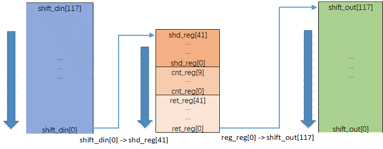
Wrap_rtc module periodically sends rtc_info_valid pulse and rtc_info_data. Rtc_sio module sends goto_rtc command and RTC time data to RTC_IO module. RTC_IO module temporarily stores the RTC time data contained in ctrl_si/ctrl_data to shd_reg, meanwhile stores the original rtc time data in shd_reg to ret_reg, sets cnt_reg to zero and starts counting as Figure 1-7 shows. When cnt_reg counts to 768, the wait is considered timeout.
The default value of PREDIV_A [8:0] is 9 ‘h7F in the wrap_rtc module, which is work in the sdm32k clock domain. The corresponding rtc_info_valid interval is about 1/256s, so while waiting for new RTC time data, According to the frequency of cnt_reg’s drive clock is 131k, it can be calculated that cnt_reg counts to about 512 when new RTC time data is received.
Considering osc131k’s maximum error of 7.125%, cnt_reg may count up to 548, so it is reliable to judge the wait timeout by counting cnt_reg up to 768. However, considering that PREDIV_A[8:0] can be written to a larger value and cause cnt_reg error judgment timeout, software is required to limit the write value of PREDIV_A[8:0] to no greater than the default value.
Note
PREDIV_A[8:0] can’t be set to greater than the default value. PREDIV_A[8:0] is RTC module’s register and its address is 0x4100_8A0C[24:16].
Shifting Data In and Out
When work in MODE_SHIFT_ENABLE, rtc_sio sends the go_test command to RTC_IO, this operation will result in following behavior:
Rtc_sio sends the value of registers rw_rtc_test_din[117:0] to RTC_IO
Rtc_sio reads back the data saved in RTC_IO, through register rtc_test_dout[117:0]
Data transmission is realized by means of shift register, and the shift length is 118, as the following figure shows.
When shift data finished and work in MODE_SHIFT_DISABLE, HW will update rtc time data into shd_reg periodically, and the primary time data in shd_reg will be stored into ret_reg.
Operation Flow
Configuring and Shifting Data
Enter MODE_RTC_START Mode
To enable rtc_mode manually, perform the following step:
Write 2’d2 to register rtc_io_ctrl[1:0] whose address is 0x41008048.
Receive and Transmit Data
To shift LDO_RCAL into RTC_IO and shift out time data from RTC_IO, perform the configuration steps are illustrated in the following table.
Step |
What to do |
How to do |
Register Address |
|---|---|---|---|
1 |
Acquire LDO_RCAL[5:0] value |
Read register LDO_BASE-> LDO_32K_OSC_CTRL[5:0] |
LDO_BASE->LDO_32K_OSC_CTRL mapping to 0x41008114 |
2 |
Prepare data into register that will be shifted into RTC_IO |
Write step1’s value to register rtc_io_test_din[63:58] |
rtc_io_test_din[127:0] mapping to 0x410080E4 ~ 0x410080EC |
3 |
Enter MODE_SHIFT_ENABLE mode, to start shift operation |
Write 2’d1 to register rtc_io_ctrl[1:0] |
rtc_io_ctrl mapping to 0x41008048 |
4 |
Wait some time for rtc_sio sending command to RTC_IO |
Wait 15ms |
|
5 |
Read the stored time data and counter, for further processing |
Read registers rtc_io_test_dout[127:0] |
rtc_io_test_dout[127:0] mapping to 0x410080C0 ~ 0x410080CC |
6 |
Enter MODE_SHIFT_DISABLE mode, to allow HW recover updating rtc time data into shd_reg periodically |
Write 2’d0 to register rtc_io_ctrl[1:0] |
rtc_io_ctrl mapping to 0x41008048 |
7 |
Process the read back time data in step5 |
|
rtc_io_test_dout[127:0] mapping to 0x410080C0 ~ 0x410080CC The time like second, min, hour and etc. located in respective bit field in register refer to section1.6 |
To calculate new time, following formula can be reference. However, for some complex situation need to be taken into considerations, such as seconds carrying over to minutes, minutes carrying over to hours, leap year and etc.
new_rtc_time_data = rtc_io_test_dout[33:0] + rtc_io_test_dout[83:59]
Note
The command that rtc_sio send to RTC_IO in step4 takes 5.78ms when osc131k has no frequency deviation.
If RTC module initialize time format in 12-hour format, RTC_IO module will convert it to 24-hour format and store it. Therefore, when parse the time respective field and calculate new time, this format conversion need to be considered.
Usage in Application
There are two sceneries and respective operation flow when use RTC_IO module, and this section introduce the detail usage.
To keep RTC_IO is powered on when the chip is powered off, it is supposed to perform following connections via Dupont Lines:
Connect the power supply pin of VDH_RTC to 3.3V power supply
Connect the GND of the development board to the common ground of the 3.3v power supply
For the first time power on, following these steps:
Write 6’d0 (Reset) to register rtc_io_test_din bit field, and shift into RTC_IO
RTCIO_SetRValue(RTCIO_RECV_RVAL_RST);
Perform 131K calibration, in order to acquire the calibration parameter which will be shifted into RTC_IO
OSC131K_Calibration(30000);
Acquire the RVAL produced by step(2) and shift into RTC_IO.
RTCIO_SetRValue(RTCIO_RECV_RVAL_CAL);
Prepare time data that will be set to the device, through the RTC module
RTC_TimeTypeDef RTC_TimeStruct;
RTC_TimeStructInit(&RTC_TimeStruct);
RTC_TimeStruct.RTC_Year = 2024;
RTC_TimeStruct.RTC_Hours = 10;
RTC_TimeStruct.RTC_Minutes = 20;
RTC_TimeStruct.RTC_Seconds = 30;
Initialize and enable RTC module
RCC_PeriphClockCmd(APBPeriph_RTC, APBPeriph_RTC_CLOCK, ENABLE);
RTC_StructInit(&RTC_InitStruct);
RTC_Init(&RTC_InitStruct);
RTC_SetTime(RTC_Format_BIN, &RTC_TimeStruct);
In case of the chip is re-power on, but RTC_IO domain keeps powering on during power off period, it is supposed to follow these steps:
Check the BOOT_Reason() return value.
Continue the next steps when return 0, otherwise do nothing.
Check the RTCIO_IsEnabled() return value.
Continue the next steps when return TRUE, otherwise perform the procedures as mentioned above for the first time power on.
Shift out the stored time data and counter during power off period
RTCIO_TimeInfo RTCIO_TimeStruct;
RTC_TimeTypeDef RTC_TimeStruct;
if(BOOT_Reason() == 0)
{
if (RTCIO_IsEnabled() == TRUE)
  {
/* shift out bkup data */
RTCIO_GetTimeInfo(&RTCIO_TimeStruct);
      /* calculate new Time */
    app_calc_new_time(&RTCIO_TimeStruct, &RTC_TimeStruct);
    }
}
Calculate new time through the structure RTCIO_TimeStruct, and the result store into struct RTC_TimeStruct. The later will be set to the device.
The function app_calc_new_time() is just example. It should be achieved according to actual application.
Initialize and enable RTC module again as the step(5) in first time power on. And setting the above calculated new time to device.
Registers
Name |
Address |
Width |
Description |
|---|---|---|---|
REG_AON_RTC_IO_CTRL |
0x41008048 |
32 bits |
0x41008048[4]: RTC IO mode flag (Read Only)
|
0x41008048[1:0]: RTC IO control mode (R/W)
|
|||
rtc_io_test_din |
0x420080E0 |
128 bits |
0x410080E0[63:58]: LDO_RCAL value
|
rtc_io_test_dout |
0x410080C0 |
128 bits |
0x410080C0[33:0]: Binary storage for year/day/hour/minute/second (e.g.: 33sec saved as sec[5:0]=6’b10_0001)
|
0x410080C0 [83:42]: Counter during power-off period, the counter clock is OSC131K. |