Thermal Sensor
Supported ICs[ RTL8720E ][ RTL8726E ][ RTL8713E ][ RTL8730E ][ RTL8721F ]
Introduction
The thermal meter of AmebaSmart is used to monitor the temperature inside the chip, and provide low-temperature warning, high-temperature warning and over-temperature protection.
When the temperature exceeds the limit high-temperature threshold, interrupt will be send to the CPU, and CPU can reduce the frequency.
When the temperature exceeds the limit low-temperature threshold, interrupt will be send to the CPU, and CPU can increase the frequency.
When the temperature exceeds the limit over-temperature protection threshold, hardware will automatically power down for over-temperature protection.
Features
No calibration
Power: 3.3V/0.9V
Measurement range: ─40°C ~ 125°C
Variation: ±1.5°C (typical), ±5°C (worst)
Resolution: 0.0125°C
Clock: 2MHz
19-bit thermal temperature value: 1 signed bit, 8 integer bits, and 10 decimal bits
Provides low- temperature warning, high-temperature warning and over-temperature protection
Provides thermal enable and over-temperature protection enable write access control
Functional Description
Block Diagram
The thermal block diagram is shown in the following figure.

The thermal includes the following sub-modules:
Bias circuit
Generates bias current for bipolar core
Bipolar core
Generates temperature-dependent voltages and
∑-∆ ADC
Contains ∑-∆ modulator and decimation filter
Output temperature-dependent digital value
Controller
Controls and manages the interrupt
Controls low- temperature warning, high-temperature warning and over-temperature protection
Register
Contains configuration registers, result registers, interrupt registers
The interface to software
Measured temperature can be read directly from the register
Bipolar Core
In order to produce a digital temperature reading, a ratio-metric measurement has to be performed: a temperature-dependent signal has to be compared to a reference signal.
While virtually every device has temperature-dependent characteristics, two diode-connected substrate PNP transistors are used to generate two voltages: a positive temperature coefficient voltage and a negative temperature coefficient voltage . They can be used to generate both a voltage that is accurately proportional to absolute temperature (PTAT), and a temperature-independent bandgap reference voltage.
The substrate PNP transistors block diagram is shown in the following figure.

The relationship between temperature and with is shown in the following figure.

\(V_{PTAT} = \alpha \times V_{BE}\), is proportional to absolute temperature.
\(V_{REF} = V_{BE} + \alpha \times V_{BE}\), is a conventional bandgap reference voltage (around 1.2V), with a zero temperature coefficient.
\(\mu\) is proportional to temperature, \(\alpha\) should be chosen reasonably to realize \(V_{REF}\).
∑-∆ ADC
∑-∆ ADC contains ∑-∆ modulator and decimation filter. and are input to a ∑-∆ modulator, which produces a bit-stream bs, of which the average value \(\mu\) is equal to the ratio of \(\alpha \times V_{BE}\) and \(V_{REF}\) . A decimation filter is used to filter the quantization noise from the bit-stream bs and perform the required scaling to obtain the ADC output Dout.
∑-∆ modulator block diagram is shown in the following figure.
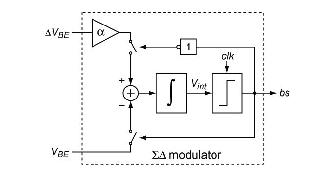
∑-∆ modulator consists of a loop filter and a clocked comparator. For simplicity, only a first-order loop filter is shown. In the actual modulator, a second-order filter is used. Every clock cycle, the comparator produces a bit of the bit-stream bs based on the polarity of the output Vint of the loop filter. The feedback is arranged to drive the output of the integrator to zero.
If the bit-stream in a given clock cycle is zero, \(\alpha \times V_{BE}\) is integrated, while is integrated if the bit-stream is one. This can be expressed as follows:
As a result of the feedback in the modulator, the average input to the integrator is zero. In other words, the charge added by is balanced by the charge removed by .
So ∑-∆ modulator realizes the quantization of μ.
Power-on Flow
Since thermal mainly uses analog circuit to measure temperature, and analog circuit needs to take a while to stabilize after power on, so additional operations are needed to get the correct temperature.
Thermal keeps power on in default state. When the system powers on, thermal is on too. But the analog circuit is not stable now, so the current temperature is not correct. To fix this problem, latch is configured to enable in default state, after 10 cycles later, latch is disabled automatically.
The power-on flow of thermal can be described as the following figure.

Power-on temperature (temp_out_poweron) is the first temperature measured after latch disabled with thermal stabilized. Also tm_max and tm_min start recording only after thermal is stable.
Registers Access Control
The values of thermal registers can be obtained directly by reading the registers’ addresses. Also, most of the thermal registers’ bits can be programmed by writing values to the registers’ addresses directly.
There are only five bits write access different from other bits. The five special bits are: tm_pow, tm_powcut, tm_rstb, tm_highcmp_pt_en and tm_high_pt_thr. The special bits write flow is illustrated in the following figure.

The grant code is used to protect special bits write in case that incorrect operation causes thermal disable and over-temperature protection disable, or high temperature protection threshold wrong.
Note
Configuration with TM OSR greater than or equal to three is not supported.
Registers
Base Address: 0x4101D000
Name |
Address offset |
Access |
Description |
|---|---|---|---|
000h |
R/W |
Thermal parameter a |
|
004h |
R/W |
Thermal parameter b |
|
008h |
R/W |
Thermal control register,config thermal parameter |
|
00Ch |
R/W |
Thermal threshold control register,config warning and low temperature threshold |
|
010h |
R |
Thermal result register |
|
014h |
R |
Thermal ADC result register,for debug |
|
018h |
R/W |
Record thermal max temperature |
|
01Ch |
R/W |
Record thermal min temperature |
|
020h |
R |
Record thermal output temperature when power on reset |
|
024h |
R/W |
Thermal interrupt control register |
|
028h |
R/W |
Thermal interrupt status register |
|
02Ch |
R/W |
Thermal time register,when over protect temperature,time count value |
|
030h |
R/W |
REG_TM_GAIN
Name : Thermal Meter Gain Register
Size : 32
Address offset : 000h
Read/write access : R/W
Thermal parameter a
Bit |
Symbol |
Access |
Reset |
Description |
|---|---|---|---|---|
31:29 |
RSVD |
R |
- |
Reserved |
28:0 |
TM_A |
R/W |
0x08284000 |
This bit defines thermal meter gain.
|
REG_TM_OFFSET
Name : Thermal Meter Offset Register
Size : 32
Address offset : 004h
Read/write access : R/W
Thermal parameter b
Bit |
Symbol |
Access |
Reset |
Description |
|---|---|---|---|---|
31:22 |
RSVD |
R |
- |
Reserved |
21:0 |
TM_B |
R/W |
0x00371700 |
This bit defines thermal meter offset.
|
REG_TM_CTRL
Name : Thermal Meter Control Register
Size : 32
Address offset : 008h
Read/write access : R/W
Thermal control register,config thermal parameter
Bit |
Symbol |
Access |
Reset |
Description |
|---|---|---|---|---|
31:24 |
TM_PWR |
R/W |
0x69 |
Thm protect password. Tm_pow,tm_powcut,tm_rstb,tm_highcmp_pt_en,tm_high_pt_thr, is o_thm can be programed only when this value is 8’h69. |
23:22 |
RSVD |
R |
- |
Reserved |
21 |
TM_POW |
R/W |
0x1 |
Thermal poweron signal
|
20 |
TM_POWCUT |
R/W |
0x1 |
Power cut
|
19 |
TM_CLK_INV_SEL |
R/W |
0x0 |
Clock phase invert select when read temperature.
|
18 |
TM_RSTB |
R/W |
0x1 |
Thermal reset signal.
|
17:14 |
TM_CHOPFREQSEL |
R/W |
0x1 |
Chop frequecy select
|
13:11 |
TM_OSR |
R/W |
0x0 |
Deci filter DSR select
|
10 |
TM_HOLD_EN |
R/W |
0x0 |
Hold output |
9:8 |
TM_HOLD_DLY |
R/W |
0x1 |
Hold delay, adjust TM_CLK_OUT width |
7 |
TM_CHOP_EN |
R/W |
0x1 |
Chop enable |
6 |
TM_EN_LATCH |
R/W |
0x1 |
Latch thermal sensor output immediately after power on for m ore accurate test |
5:4 |
TM_BIAS_SEL |
R/W |
0x1 |
Select ADC bias current
|
3 |
TM_BIASDEM_EN |
R/W |
0x1 |
Bias DEM enable |
2:1 |
RSVD |
R |
- |
Reserved |
0 |
TM_ADCCKSEL |
R/W |
0x1 |
Selelct ADC fs
|
REG_TM_TH_CTRL
Name : Thermal Meter Threshold Control Register
Size : 32
Address offset : 00Ch
Read/write access : R/W
Thermal threshold control register,config warning and low temperature threshold
Bit |
Symbol |
Access |
Reset |
Description |
|---|---|---|---|---|
31 |
RSVD |
R |
- |
Reserved |
30 |
ISO_THM |
R/W |
0x0 |
|
29 |
TM_HIGHCMP_PT_EN |
R/W |
0x0 |
To enable compare tm_out with over temperature protect thres hold: When tm_out[18:10] > tm_high_pt_thr, it will set aon reset.
|
28:20 |
TM_HIGH_PT_THR |
R/W |
0x07D |
Set over temperature protection threshold for comparison wit h TEMP_OUT. Only between 0x046 (70°C) and 0x08C (140°C) are valid.
|
19 |
TM_HIGHCMP_WT_EN |
R/W |
0x0 |
To enable compare tm_out with over temperature warning thres hold: When tm_high_thr <= tm_out[18:10] < tm_high_pt_thr, it will set Interrupt pending flag ISR_TM_HIGH.
|
18:10 |
TM_HIGH_WT_THR |
R/W |
0x069 |
Set the over temperature warning threshold for comparison wi th TEMP_OUT.Only values greater than 0 are supported
|
9 |
TM_LOWCMP_WT_EN |
R/W |
0x0 |
To enable compare TM_OUT with set Low threshold: When tm_out[18:10] <= tm_low_thr, it will set Interrupt pend ing flag ISR_TM_LOW.
|
8:0 |
TM_LOW_WT_THR |
R/W |
0x1D8 |
Set the Low threshold for comparison with TEMP_OUT.
|
REG_TM_RESULT
Name : Thermal Meter Temperature Result Register
Size : 32
Address offset : 010h
Read/write access : R
Thermal result register
Bit |
Symbol |
Access |
Reset |
Description |
|---|---|---|---|---|
31:19 |
RSVD |
R |
- |
Reserved |
18:0 |
TM_OUT |
R |
0x0 |
This bit defines real temperature. The result refreshes in r eal time.
|
REG_TM_ADC_RESULT
Name : Thermal Meter ADC Result Register
Size : 32
Address offset : 014h
Read/write access : R
Thermal ADC result register,for debug
Bit |
Symbol |
Access |
Reset |
Description |
|---|---|---|---|---|
31:22 |
RSVD |
R |
- |
Reserved |
21:0 |
TM_ADC_OUT |
R |
0x0 |
This bit defines thermal meter ADC output. The result refres hes in real time.
|
REG_TM_MAX_CTRL
Name : Thermal Meter Max Temperature Control Register
Size : 32
Address offset : 018h
Read/write access : R/W
Record thermal max temperature
Bit |
Symbol |
Access |
Reset |
Description |
|---|---|---|---|---|
31:20 |
RSVD |
R |
- |
Reserved |
19 |
TM_MAX_CLR |
R/W |
0x0 |
This bit defines clear max temperature
|
18:0 |
TM_MAX |
R |
0x40000 |
These bits define max temperature. |
REG_TM_MIN_CTRL
Name : Thermal Meter Min Temperature Control Register
Size : 32
Address offset : 01Ch
Read/write access : R/W
Record thermal min temperature
Bit |
Symbol |
Access |
Reset |
Description |
|---|---|---|---|---|
31:20 |
RSVD |
R |
- |
Reserved |
19 |
TM_MIN_CLR |
R/W |
0x0 |
This bit defines clear min temperature
|
18:0 |
TM_MIN |
R |
0x3FFFF |
These bits define min temperature. |
REG_TM_OUT_PWR_ON
Name : Thermal Meter Power On Temperature Register
Size : 32
Address offset : 020h
Read/write access : R
Record thermal output temperature when power on reset
Bit |
Symbol |
Access |
Reset |
Description |
|---|---|---|---|---|
31:19 |
RSVD |
R |
- |
Reserved |
18:0 |
TEMP_OUT_POWERON |
R |
0x0 |
This bit defines output temperature when power on reset.
|
REG_TM_INTR_CTRL
Name : Thermal Meter Interrupt Control Register
Size : 32
Address offset : 024h
Read/write access : R/W
Thermal interrupt control register
Bit |
Symbol |
Access |
Reset |
Description |
|---|---|---|---|---|
31:2 |
RSVD |
R |
- |
Reserved |
1 |
IMR_TM_LOW_WT |
R/W |
0x0 |
Interrupt control for thermal meter detect low temperature.
|
0 |
IMR_TM_HIGH_WT |
R/W |
0x0 |
Interrupt control for thermal meter detect over temperature warning.
|
REG_TM_INTR_STS
Name : Thermal Meter Interrupt Status Register
Size : 32
Address offset : 028h
Read/write access : R/W
Thermal interrupt status register
Bit |
Symbol |
Access |
Reset |
Description |
|---|---|---|---|---|
31:2 |
RSVD |
R |
- |
Reserved |
1 |
ISR_TM_LOW_WT |
R/W |
0x0 |
Interrupt pending flag for thermal meter detect low temperat ure.
|
0 |
ISR_TM_HIGH_WT |
R/W |
0x0 |
Interrupt pending flag for thermal meter detect over tempera ture warning.
|
REG_TM_TIMER
Name : Thermal Meter Timer Register
Size : 32
Address offset : 02Ch
Read/write access : R/W
Thermal time register,when over protect temperature,time count value
Bit |
Symbol |
Access |
Reset |
Description |
|---|---|---|---|---|
31:8 |
RSVD |
R |
- |
Reserved |
7:0 |
TIME_PERIOD |
R/W |
0x0F |
Time period of auto power on |
REG_TM_DUMMY
Name : Thermal Dummy Register
Size : 32
Address offset : 030h
Read/write access : R/W
Bit |
Symbol |
Access |
Reset |
Description |
|---|---|---|---|---|
31:16 |
RSVD |
R |
- |
Reserved |
15:0 |
DUMMY |
R/W |
0x0 |
Rsvd for hw |
Base Address: 0x42013000
Name |
Address offset |
Access |
Description |
|---|---|---|---|
000h |
R/W |
Thermal parameter a |
|
004h |
R/W |
Thermal parameter b |
|
008h |
R/W |
Thermal control register,config thermal parameter |
|
00Ch |
R/W |
Thermal threshold control register,config warning and low temperature threshold |
|
010h |
R |
Thermal result register |
|
014h |
R |
Thermal ADC result register,for debug |
|
018h |
R/W |
Record thermal max temperature |
|
01Ch |
R/W |
Record thermal min temperature |
|
020h |
R |
Record thermal output temperature when power on reset |
|
024h |
R/W |
Thermal interrupt control register |
|
028h |
R/W |
Thermal interrupt status register |
|
02Ch |
R/W |
Thermal time register,when over protect temperature,time count value |
REG_TM_GAIN
Name : Thermal Meter Gain Register
Size : 32
Address offset : 000h
Read/write access : R/W
Thermal parameter a
Bit |
Symbol |
Access |
Reset |
Description |
|---|---|---|---|---|
31:29 |
RSVD |
R |
- |
Reserved |
28:0 |
TM_A |
R/W |
0x08284000 |
This bit defines thermal meter gain.
|
REG_TM_OFFSET
Name : Thermal Meter Offset Register
Size : 32
Address offset : 004h
Read/write access : R/W
Thermal parameter b
Bit |
Symbol |
Access |
Reset |
Description |
|---|---|---|---|---|
31:22 |
RSVD |
R |
- |
Reserved |
21:0 |
TM_B |
R/W |
0x00371A00 |
This bit defines thermal meter offset.
|
REG_TM_CTRL
Name : Thermal Meter Control Register
Size : 32
Address offset : 008h
Read/write access : R/W
Thermal control register,config thermal parameter
Bit |
Symbol |
Access |
Reset |
Description |
|---|---|---|---|---|
31:24 |
TM_PWR |
R/W |
0x69 |
Thm protect password. Tm_pow,tm_powcut,tm_rstb,tm_highcmp_pt_en can be programed o nly when this value is 8’h69. |
23:22 |
RSVD |
R |
- |
Reserved |
21 |
TM_POW |
R/W |
0x1 |
Thermal poweron signal
|
20 |
TM_POWCUT |
R/W |
0x1 |
Power cut
|
19 |
TM_CLK_INV_SEL |
R/W |
0x0 |
Clock phase invert select when read temperature.
|
18 |
TM_RSTB |
R/W |
0x1 |
Thermal reset signal.
|
17:14 |
TM_CHOPFREQSEL |
R/W |
0x1 |
Chop frequecy select
|
13:11 |
TM_OSR |
R/W |
0x0 |
Deci filter DSR select
|
10 |
TM_HOLD_EN |
R/W |
0x0 |
Hold output |
9:8 |
TM_HOLD_DLY |
R/W |
0x1 |
Hold delay, adjust TM_CLK_OUT width |
7 |
TM_CHOP_EN |
R/W |
0x1 |
Chop enable |
6 |
TM_EN_LATCH |
R/W |
0x1 |
Latch thermal sensor output immediately after power on for m ore accurate test |
5:4 |
TM_BIAS_SEL |
R/W |
0x1 |
Select ADC bias current
|
3 |
TM_BIASDEM_EN |
R/W |
0x1 |
Bias DEM enable |
2:1 |
RSVD |
R |
- |
Reserved |
0 |
TM_ADCCKSEL |
R/W |
0x1 |
Selelct ADC fs
|
REG_TM_TH_CTRL
Name : Thermal Meter Threshold Control Register
Size : 32
Address offset : 00Ch
Read/write access : R/W
Thermal threshold control register,config warning and low temperature threshold
Bit |
Symbol |
Access |
Reset |
Description |
|---|---|---|---|---|
31:30 |
RSVD |
R |
- |
Reserved |
29 |
TM_HIGHCMP_PT_EN |
R/W |
0x0 |
To enable compare tm_out with over temperature protect thres hold: When tm_out[18:10] > tm_high_pt_thr, it will set aon reset.
|
28:20 |
TM_HIGH_PT_THR |
R/W |
0x07D |
Set over temperature protection threshold for comparison wit h TEMP_OUT. Only between 0x046 (70°C) and 0x08C (140°C) are valid.
|
19 |
TM_HIGHCMP_WT_EN |
R/W |
0x0 |
To enable compare tm_out with over temperature warning thres hold: When tm_high_thr <= tm_out[18:10] < tm_high_pt_thr, it will set Interrupt pending flag ISR_TM_HIGH.
|
18:10 |
TM_HIGH_WT_THR |
R/W |
0x069 |
Set the over temperature warning threshold for comparison wi th TEMP_OUT.Only values greater than 0 are supported
|
9 |
TM_LOWCMP_WT_EN |
R/W |
0x0 |
To enable compare TM_OUT with set Low threshold: When tm_out[18:10] <= tm_low_thr, it will set Interrupt pend ing flag ISR_TM_LOW.
|
8:0 |
TM_LOW_WT_THR |
R/W |
0x1D8 |
Set the Low threshold for comparison with TEMP_OUT.
|
REG_TM_RESULT
Name : Thermal Meter Temperature Result Register
Size : 32
Address offset : 010h
Read/write access : R
Thermal result register
Bit |
Symbol |
Access |
Reset |
Description |
|---|---|---|---|---|
31:19 |
RSVD |
R |
- |
Reserved |
18:0 |
TM_OUT |
R |
0x0 |
This bit defines real temperature. The result refreshes in r eal time.
|
REG_TM_ADC_RESULT
Name : Thermal Meter ADC Result Register
Size : 32
Address offset : 014h
Read/write access : R
Thermal ADC result register,for debug
Bit |
Symbol |
Access |
Reset |
Description |
|---|---|---|---|---|
31:22 |
RSVD |
R |
- |
Reserved |
21:0 |
TM_ADC_OUT |
R |
0x0 |
This bit defines thermal meter ADC output. The result refres hes in real time.
|
REG_TM_MAX_CTRL
Name : Thermal Meter Max Temperature Control Register
Size : 32
Address offset : 018h
Read/write access : R/W
Record thermal max temperature
Bit |
Symbol |
Access |
Reset |
Description |
|---|---|---|---|---|
31:20 |
RSVD |
R |
- |
Reserved |
19 |
TM_MAX_CLR |
R/W |
0x0 |
This bit defines clear max temperature
|
18:0 |
TM_MAX |
R |
0x40000 |
These bits define max temperature. |
REG_TM_MIN_CTRL
Name : Thermal Meter Min Temperature Control Register
Size : 32
Address offset : 01Ch
Read/write access : R/W
Record thermal min temperature
Bit |
Symbol |
Access |
Reset |
Description |
|---|---|---|---|---|
31:20 |
RSVD |
R |
- |
Reserved |
19 |
TM_MIN_CLR |
R/W |
0x0 |
This bit defines clear min temperature
|
18:0 |
TM_MIN |
R |
0x3FFFF |
These bits define min temperature. |
REG_TM_OUT_PWR_ON
Name : Thermal Meter Power On Temperature Register
Size : 32
Address offset : 020h
Read/write access : R
Record thermal output temperature when power on reset
Bit |
Symbol |
Access |
Reset |
Description |
|---|---|---|---|---|
31:19 |
RSVD |
R |
- |
Reserved |
18:0 |
TEMP_OUT_POWERON |
R |
0x0 |
This bit defines output temperature when power on reset.
|
REG_TM_INTR_CTRL
Name : Thermal Meter Interrupt Control Register
Size : 32
Address offset : 024h
Read/write access : R/W
Thermal interrupt control register
Bit |
Symbol |
Access |
Reset |
Description |
|---|---|---|---|---|
31:2 |
RSVD |
R |
- |
Reserved |
1 |
IMR_TM_LOW_WT |
R/W |
0x0 |
Interrupt control for thermal meter detect low temperature.
|
0 |
IMR_TM_HIGH_WT |
R/W |
0x0 |
Interrupt control for thermal meter detect over temperature warning.
|
REG_TM_INTR_STS
Name : Thermal Meter Interrupt Status Register
Size : 32
Address offset : 028h
Read/write access : R/W
Thermal interrupt status register
Bit |
Symbol |
Access |
Reset |
Description |
|---|---|---|---|---|
31:2 |
RSVD |
R |
- |
Reserved |
1 |
ISR_TM_LOW_WT |
R/W |
0x0 |
Interrupt pending flag for thermal meter detect low temperat ure.
|
0 |
ISR_TM_HIGH_WT |
R/W |
0x0 |
Interrupt pending flag for thermal meter detect over tempera ture warning.
|
REG_TM_TIMER
Name : Thermal Meter Timer Register
Size : 32
Address offset : 02Ch
Read/write access : R/W
Thermal time register,when over protect temperature,time count value
Bit |
Symbol |
Access |
Reset |
Description |
|---|---|---|---|---|
31:8 |
RSVD |
R |
- |
Reserved |
7:0 |
TIME_PERIOD |
R/W |
0x0F |
Time period of auto power on |