PSRAM AXI Clutch
Introduction
Check if psram controller has axi access, start idle counter when there’s no axi access. Once the idle counter reaching the preset idle value, shutdown DQ pads’ rx path by asserting high to DQ pads’ PD pin and axi access will be blocked. If there is axi access to psram controller afterwards, DQ pads will resume first and this resume process takes tens of nanoseconds(50ns at worst corner). Axi acess will still be blocked until the resume counter reaching the preset resume value
Some information from pad designer:
PAD的PD pin只對自己的Rx有作用,
PWDPAD15N=0是關掉DDR domain的level shifter, 包括REF, ZQ…等.從DQ PAD Rx的角度出發, 兩個的效果是一樣的, 但是對DDR PAD domain的leakage有些微的差異
There are two options to power down DDR pads as shown below:
PWDPAD15N(3.3V) |
PD |
Tx |
Rx |
|---|---|---|---|
0 |
1/0 |
Power down |
Power down |
0 |
0 |
Power down |
Power down |
1 |
1 |
Controlled by |
Power down |
1 |
0 |
Controlled by |
Power on |
Using pwdpad15n to shutdown both DQ pads’ tx and rx path can minimize DQ pads’ power consumption. However, pwdpad15n signal must raise its voltage to 3.3V by going through level shift(regu) whose delay is more than 100ns at typical case. This can impact ddr performance since we must wait enough time to bypass this level shift delay every time we resume pads from power down state.
Using PD to shutdown DQ pads’ rx path will result in the power consumption slightly more than the case using pwdpad15n, while PD signal can come directly from AMEBACORE power domain. dq_se[15:0] (connecting to E pin) and dq_ie[15:0] (connecting to TE pin) are all being kept low at idle state or self-refresh state.
Besides, DQ pads need some time(50ns at worst case) when resuming from power down state. Thus we will only use PD pin to power down DQ pads’ rx path in this design.
Power consumption of DDR pads at different cases is listed below.
PWDPAD15 |
PD |
Core电流 |
IO 电流 |
|
|---|---|---|---|---|
DQ区 |
0 |
N/A |
55.7uA |
593.2uA |
DQ区 |
3.3 |
1 (with E=0 & TE=0) |
+70uA(TC corner), compared with PWDPAD15=0 |
+70uA(TC corner), compared with PWDPAD15=0 |
DQ区 |
3.3 |
0 |
34.6uA |
35.6mA |
Features
Unit of idle counter: 1us
Max idle value: 512us, configured by register
Functional Description
Block Diagram
psram_axi_clutch block diagram is shown below.

psram_pad_pwd connection is shown below.

(Optional) Clock Diagram
Xtal_ck1m which comes from hs_timer xtal_peri_div40 is used by idle counter. Axi access is used as the reset signal to clear idle counter, thus there will be a margin of error (0 ~ +1us).
Registers
Base Address: 0x41000000
Name |
Address offset |
Access |
Description |
|---|---|---|---|
000h |
R/W |
||
004h |
R/W |
||
008h |
R/W |
||
00Ch |
R/W |
||
010h |
R/W |
||
030h |
R/W |
||
034h |
R/W |
||
038h |
R/W |
||
03Ch |
R/W |
||
040h |
R/W |
||
060h |
R/W |
||
064h |
R/W |
||
070h |
R/W |
||
080h |
R/W |
||
090h |
R/W |
||
094h |
R |
||
098h |
R |
||
180h |
R/W |
||
184h |
R/W |
||
188h |
R/W |
||
18Ch |
R/W |
||
1E0h |
R/W |
||
1E4h |
R/W |
||
1E8h |
R/W |
||
1ECh |
R/W |
||
1F0h |
R/W |
||
1F4h |
R/W |
||
1F8h |
R/W |
||
1FCh |
R/W |
REG_HP_PWC
Size : 32
Address offset : 000h
Read/write access : R/W
Bit |
Symbol |
Access |
Reset |
Description |
|---|---|---|---|---|
31:30 |
PSW_HP_AP_CORE_2ND_OUT |
R |
0 |
AP macro core power domain 2nd switch state, active 1 [0]: core0 [1]: core1 |
29:28 |
PSW_HP_AP_CORE_OUT |
R |
0 |
AP macro core power domain switch state,active 1 [0]: core0 [1]: core1 |
27 |
PSW_HP_AP_SOC_OUT |
R |
0 |
SOC AP top power domain switch state,active 1 |
26 |
PSW_HP_AP_TOP_2ND_OUT |
R |
0 |
AP macro top power domain 2nd switch state |
25 |
PSW_HP_AP_TOP_OUT |
R |
0 |
AP macro top power domain switch state,active 1 |
24 |
PSW_HP_AP_L2_OUT |
R |
0 |
AP macro L2 power domain switch state,active 1 |
23:8 |
RSVD |
R |
- |
Reserved |
7:6 |
PSW_HP_AP_CORE_2ND |
R/W |
0 |
AP macro core power domain 2nd switch enable,active 1 [0]: core0 [1]: core1 |
5:4 |
PSW_HP_AP_CORE |
R/W |
0 |
AP macro core power domain switch enable,active 1 [0]: core0 [1]: core1 |
3 |
RSVD |
R |
- |
Reserved |
2 |
PSW_HP_AP_TOP_2ND |
R/W |
0 |
AP macro top power domain 2nd switch enable,active 1 |
1 |
PSW_HP_AP_TOP |
R/W |
0 |
AP macro top power domain switch enable,active 1 |
0 |
PSW_HP_AP_L2 |
R/W |
0 |
AP macro L2 power domain switch enable,active 1 |
REG_HP_ISO
Size : 32
Address offset : 004h
Read/write access : R/W
Bit |
Symbol |
Access |
Reset |
Description |
|---|---|---|---|---|
31:6 |
RSVD |
R |
- |
Reserved |
5:4 |
ISO_HP_AP_CORE |
R/W |
1 |
AP macro core power domain isolatation, 1: isolation [0]: core0 [1]: core1 |
3:2 |
RSVD |
R |
- |
Reserved |
1 |
ISO_HP_AP_TOP |
R/W |
1 |
AP macro top power domain isolatation, 1: isolation |
0 |
RSVD |
R |
- |
Reserved |
REG_HP_FEN
Size : 32
Address offset : 008h
Read/write access : R/W
Bit |
Symbol |
Access |
Reset |
Description |
|---|---|---|---|---|
31:1 |
RSVD |
R |
- |
Reserved |
0 |
FEN_AP |
R/W |
0 |
CA7 function enable |
REG_HP_CKE
Size : 32
Address offset : 00Ch
Read/write access : R/W
Bit |
Symbol |
Access |
Reset |
Description |
|---|---|---|---|---|
31:1 |
RSVD |
R |
- |
Reserved |
0 |
CKE_AP |
R/W |
0 |
CA7 clock enable . |
REG_HP_CKSL
Size : 32
Address offset : 010h
Read/write access : R/W
Bit |
Symbol |
Access |
Reset |
Description |
|---|---|---|---|---|
31:4 |
RSVD |
R |
- |
Reserved |
3:2 |
CKSL_AP |
R/W |
0 |
CA7 clock selection
|
1:0 |
CKD_AP |
R/W |
0 |
CA7 clock divider , this is after clk select by cksl_ap
|
REG_HPLAT_CTRL
Size : 32
Address offset : 030h
Read/write access : R/W
Bit |
Symbol |
Access |
Reset |
Description |
|---|---|---|---|---|
31:29 |
RSVD |
R |
- |
Reserved |
28 |
PSRAM_SPIC_BIG_ENDIAN |
R/W |
0 |
|
27 |
RSVD |
R |
- |
Reserved |
26 |
SPI1_MST |
R/W |
0h |
|
25 |
SPI0_MST |
R/W |
0h |
|
24 |
EXT_MEM_IS_DDR |
R/W |
0 |
System DDR PSRAM select
|
23 |
DDRC_SPDUPSIM |
R/W |
0 |
Ddrc simulatin speedup enable |
22:21 |
GDMA0_CCM |
R/W |
0h |
GDMA0 clock control mode |
20 |
PSRAM_SPDUPSIM |
R/W |
0 |
Psramc simulatin speedup enable |
19 |
PLFM_AUTO_ICG_EN |
R/W |
0 |
|
18 |
SHARE_BT_MEM |
R/W |
0 |
|
17 |
SHARE_WL_MEM |
R/W |
0 |
|
16 |
KM4_RETENTION_MODE |
R/W |
0 |
|
15:1 |
RSVD |
R |
- |
Reserved |
0 |
HW_PDN_AUD |
R/W |
1 |
After enable audio swr , then this bit set to 1 . Before shutdown audio swr , this bit must set to 0 . Default 1 for old project . |
REG_HPLAT_STATUS
Size : 32
Address offset : 034h
Read/write access : R/W
Bit |
Symbol |
Access |
Reset |
Description |
|---|---|---|---|---|
31:17 |
RSVD |
R |
- |
Reserved |
16 |
INIT_XO_RANGE_EN |
R/W |
1 |
|
15:13 |
RSVD |
R |
- |
Reserved |
12 |
SHARE_CACHE_MEM |
R/W |
0 |
Global control for cache shared with dtcm0
|
11 |
RSVD |
R |
- |
Reserved |
10 |
DRAM_ADAP_IDLE |
R |
0 |
|
9 |
LX2_MST_IDLE |
R |
0 |
Indicate Lx2 mst is idle |
8 |
LX1_MST_IDLE |
R |
0 |
Indicate Lx1 mst is idle |
7:4 |
RSVD |
R |
- |
Reserved |
3 |
KM4_DBGRESTARTED_M |
R |
0 |
KM4 debug restart status |
2 |
KM4_HALTED_M |
R |
0 |
KM4 halt status |
1 |
KM4_LOCKUP_M |
R |
0 |
KM4 lockup status |
0 |
KM4_SL_SLEEPSYS_R |
R |
0 |
KM4 sleep status |
REG_KM4_XO_CTRL0
Size : 32
Address offset : 038h
Read/write access : R/W
Bit |
Symbol |
Access |
Reset |
Description |
|---|---|---|---|---|
31:0 |
INIT_XO_BASE |
R/W |
32’h140 |
REG_KM4_XO_CTRL1
Size : 32
Address offset : 03Ch
Read/write access : R/W
Bit |
Symbol |
Access |
Reset |
Description |
|---|---|---|---|---|
31:0 |
INIT_XO_TOP |
R/W |
32’h98e0 |
REG_SPIC_CTRL
Size : 32
Address offset : 040h
Read/write access : R/W
Bit |
Symbol |
Access |
Reset |
Description |
|---|---|---|---|---|
31:16 |
RSVD |
R |
- |
Reserved |
15 |
FLASH_CAL_EN |
R/W |
0 |
Flash calibration enable
|
14 |
RSVD |
R |
- |
Reserved |
13 |
FLASH_DIV_EN |
R/W |
0 |
|
12 |
FLASH_PS_DIV_EN |
R/W |
0 |
|
11:8 |
FLASH_DIV_INT |
R/W |
0 |
Flash clock division ratio, integrate part
Note SPI clock frequency is this divided clock/2 |
7 |
RSVD |
R |
- |
Reserved |
6:2 |
FLASH_PS_PHASE |
R/W |
0 |
Flash clock phase shift in units of 1/2 np PLL clock cycles. If np PLL is 1GHz, the step is 0.5ns.
…
Note, this value cannot be set more than (FLASH_DIV_INT+1) * 2-1, for example, If DIV_INT is 1 , which means spic clock is 1/2 NPPLL , then the most shift step setting is 3, which is 4 step can be use d. |
1 |
FLASH_PS_DIV_RDY |
R |
0 |
Ready flag of Flash clock with phase shift, Read only (input signal) |
0 |
FLASH_DIV_RDY |
R |
0 |
Ready flag of Flash clock, Read only (input signal) |
REG_USB_CTRL
Size : 32
Address offset : 060h
Read/write access : R/W
Bit |
Symbol |
Access |
Reset |
Description |
|---|---|---|---|---|
31:29 |
RSVD |
R |
- |
Reserved |
28 |
USB2_DIGOTGPADEN |
R/W |
0 |
|
27 |
USB_OTGMODE |
R/W |
0 |
|
26 |
USB2_DIGPADEN |
R/W |
0 |
|
25 |
ISO_USBA_EN |
R/W |
1 |
|
24 |
ISO_USBD_EN |
R/W |
1 |
|
23 |
USBA_LDO_EN |
R/W |
0 |
|
22:21 |
RSVD |
R |
- |
Reserved |
20 |
PDN_UPHY_EN |
R/W |
1 |
|
19 |
PWC_UABG_EN |
R/W |
0 |
|
18 |
PWC_UAHV_EN |
R/W |
0 |
|
17 |
PWC_UALV_EN |
R/W |
0 |
|
16 |
OTG_ANA_EN |
R/W |
0 |
|
15:0 |
USBOTG_CTRL |
R/W |
0h |
REG_USB_TEST_CTRL
Size : 32
Address offset : 064h
Read/write access : R/W
Bit |
Symbol |
Access |
Reset |
Description |
|---|---|---|---|---|
31:10 |
RSVD |
R |
- |
Reserved |
9 |
UPHY_SLB_CMD |
R/W |
0 |
|
8 |
UPHY_DBG_CLK |
R |
0 |
|
7 |
UPHY_SLB_HS |
R/W |
0 |
|
6 |
UPHY_HS_SLB_OK |
R |
0 |
|
5 |
UPHY_SLB_HW_PRD |
R |
0 |
|
4 |
UPHY_FS_SLB_OK |
R |
0 |
|
3 |
UPHY_FORCE_SLB |
R/W |
0 |
|
2 |
UPHY_SLB_FAIL |
R |
0 |
|
1 |
UPHY_SLB_DONE |
R |
0 |
|
0 |
USB_TST_SEL |
R/W |
0h |
Select the location where the USB test signals are from
|
REG_SDH_CTRL
Size : 32
Address offset : 070h
Read/write access : R/W
Bit |
Symbol |
Access |
Reset |
Description |
|---|---|---|---|---|
31:8 |
RSVD |
R |
- |
Reserved |
7 |
SDCD_DBNC_EN |
R/W |
0 |
|
6 |
RSVD |
R |
- |
Reserved |
5:0 |
SDCD_DBNC_CNT |
R/W |
0h |
Debounce count value, unit is 1ms |
REG_DDR_CTRL
Size : 32
Address offset : 080h
Read/write access : R/W
Bit |
Symbol |
Access |
Reset |
Description |
|---|---|---|---|---|
31:2 |
RSVD |
R |
- |
Reserved |
1 |
DDRP_CLKEN_DCPHY |
R/W |
1h |
|
0 |
DDRP_CLKEN_PLLREG |
R/W |
1h |
|
REG_LXBUS_DBG_CTRL
Size : 32
Address offset : 090h
Read/write access : R/W
Bit |
Symbol |
Access |
Reset |
Description |
|---|---|---|---|---|
31:13 |
RSVD |
R |
- |
Reserved |
12 |
LX1_LOCK_OK |
R |
0 |
Lock lx1 bus lock ok |
11:9 |
RSVD |
R |
- |
Reserved |
8 |
LX1_LOCK_BUS |
R/W |
0 |
Lock lx1 bus for debug |
7:6 |
RSVD |
R |
- |
Reserved |
5:4 |
BUSTIMEOUT |
R/W |
0 |
Lx sys bus arb timeout thresh |
3:1 |
RSVD |
R |
- |
Reserved |
0 |
ENBUSTIMEOUT |
R/W |
0 |
Lx sys bus arb timeout enable |
REG_LXBUS_DBG0
Size : 32
Address offset : 094h
Read/write access : R
Bit |
Symbol |
Access |
Reset |
Description |
|---|---|---|---|---|
31:0 |
TIMEOUT_ADDR_MST |
R |
0 |
Lx sys bus addr debug out |
REG_LXBUS_DBG1
Size : 32
Address offset : 098h
Read/write access : R
Bit |
Symbol |
Access |
Reset |
Description |
|---|---|---|---|---|
31:0 |
TIMEOUT_ADDR_SLV |
R |
0 |
Lx sys bus addr debug out |
REG_RSVD_FOR_SW0
Size : 32
Address offset : 180h
Read/write access : R/W
Bit |
Symbol |
Access |
Reset |
Description |
|---|---|---|---|---|
31:0 |
DUMMY |
R/W |
0 |
HW used only , these are for reserved. |
REG_RSVD_FOR_SW1
Size : 32
Address offset : 184h
Read/write access : R/W
Bit |
Symbol |
Access |
Reset |
Description |
|---|---|---|---|---|
31:0 |
DUMMY |
R/W |
0 |
HW used only , these are for reserved. |
REG_RSVD_FOR_SW2
Size : 32
Address offset : 188h
Read/write access : R/W
Bit |
Symbol |
Access |
Reset |
Description |
|---|---|---|---|---|
31:0 |
DUMMY |
R/W |
0 |
HW used only , these are for reserved. |
REG_RSVD_FOR_SW3
Size : 32
Address offset : 18Ch
Read/write access : R/W
Bit |
Symbol |
Access |
Reset |
Description |
|---|---|---|---|---|
31:0 |
DUMMY |
R/W |
0 |
HW used only , these are for reserved. |
REG_DUMMY_1E0
Size : 32
Address offset : 1E0h
Read/write access : R/W
Bit |
Symbol |
Access |
Reset |
Description |
|---|---|---|---|---|
31:3 |
DUMMY |
R/W |
0 |
HW used only , these are for reserved. |
2 |
CKSL_TIM9 |
R/W |
0 |
Select tim9 clock source
|
1 |
PI_PWROFF_EN |
R/W |
0 |
ECO: enable to shutdown ddrphy PI + dq pads after entering s elf-refresh state, only for ddr |
0 |
PWDPAD_DQ_EN |
R/W |
0 |
ECO: enable to shutdown dq pads when idle, for both ddr and psram Must be set after configuring pwdpad_idle_val Note only stop psram auto axi access, manually enable/disable this bit when using psram user axi access |
REG_DUMMY_1E4
Size : 32
Address offset : 1E4h
Read/write access : R/W
Bit |
Symbol |
Access |
Reset |
Description |
|---|---|---|---|---|
31:17 |
DUMMY |
R/W |
15’h7fff |
HW used only , these are for reserved. |
16:14 |
PI_PWROFF_DLY |
R/W |
3’h7 |
ECO: after shutdown ddrphy CK_OE, delay several cycles(4T~8T dfi_clk) to shutdown ddrphy PI |
13:9 |
PWDPAD_RESUME_VAL |
R/W |
5’h1f |
ECO: dq pads resume counter setting, only for psram, auto ax i access will be stopped until resume done |
8:0 |
PWDPAD_IDLE_VAL |
R/W |
9’h1ff |
ECO: idle counter setting, only for psram, shutdown dq pads after reaching this value |
REG_DUMMY_1E8
Size : 32
Address offset : 1E8h
Read/write access : R/W
Bit |
Symbol |
Access |
Reset |
Description |
|---|---|---|---|---|
31:0 |
DUMMY |
R/W |
0 |
HW used only , these are for reserved. |
REG_DUMMY_1EC
Size : 32
Address offset : 1ECh
Read/write access : R/W
Bit |
Symbol |
Access |
Reset |
Description |
|---|---|---|---|---|
31:1 |
DUMMY |
R/W |
31’h7fffffff |
HW used only , these are for reserved. |
0 |
BLD_END_CNT_EN |
R/W |
1 |
ECO:LCDC bld_end cnt enable |
REG_BOUNDARY_CHK
Size : 32
Address offset : 1F0h
Read/write access : R/W
Bit |
Symbol |
Access |
Reset |
Description |
|---|---|---|---|---|
31:0 |
DUMMY |
R/W |
32’hBDC20512 |
Used for access boundary check, SYSON is 512B which is 000- 1FF. |
REG_DUMMY_1F4
Size : 32
Address offset : 1F4h
Read/write access : R/W
Bit |
Symbol |
Access |
Reset |
Description |
|---|---|---|---|---|
31:0 |
DUMMY |
R/W |
0 |
HW used only , these are for reserved. |
REG_DUMMY_1F8
Size : 32
Address offset : 1F8h
Read/write access : R/W
Bit |
Symbol |
Access |
Reset |
Description |
|---|---|---|---|---|
31:0 |
DUMMY |
R/W |
32’hffffffff |
HW used only , these are for reserved. |
REG_DUMMY_1FC
Size : 32
Address offset : 1FCh
Read/write access : R/W
Bit |
Symbol |
Access |
Reset |
Description |
|---|---|---|---|---|
31:0 |
DUMMY |
R/W |
0 |
HW used only , these are for reserved. |
Operation Flow
Shutdown DQ pads’ rx path when idle
The flow of dynamically shutdown DQ pads’ rx path is shown below.

Power down DQ pads and disable psram_phy
The flow of power down DQ pads and disable psram_phy is shown below.

Top Level Interface
The psram_axi_clutch interface is listed below.
Port Name |
I/O |
Description |
|---|---|---|
Global Signals |
Global Signals |
Global Signals |
clk |
Psram axi clock |
|
rst_n |
Rstn generated at psram_clk domain |
|
xtal_peri |
Xtal 40M clock |
|
xtal_ck1m |
Xtal 1M clock, from hs_timer xtal_div40 |
|
Register |
Register |
Register |
rw_pwdpad_dq_en |
I |
high active, enable to shutdown DQ pads when idle |
rw_pwdpad_idle_val[8:0] |
I |
idle counter setting, unit: 1us |
rw_pwdpad_resume_val[4:0] |
I |
dq pads resume counter setting, unit: psram_clk period |
AXI Signals |
AXI Signals |
AXI Signals |
… |
||
Control Signals |
Control Signals |
Control Signals |
psram_pad_pwd |
O |
High active, control DQ pads’ PD input |
Design Implementation
Idle counter
We use xtal_peri (40M) instead of xtal_ck1m for idle_rst releasing, xtal_ck1m is the generated clock from xtal_peri and STA will check the paths between these two clocks.
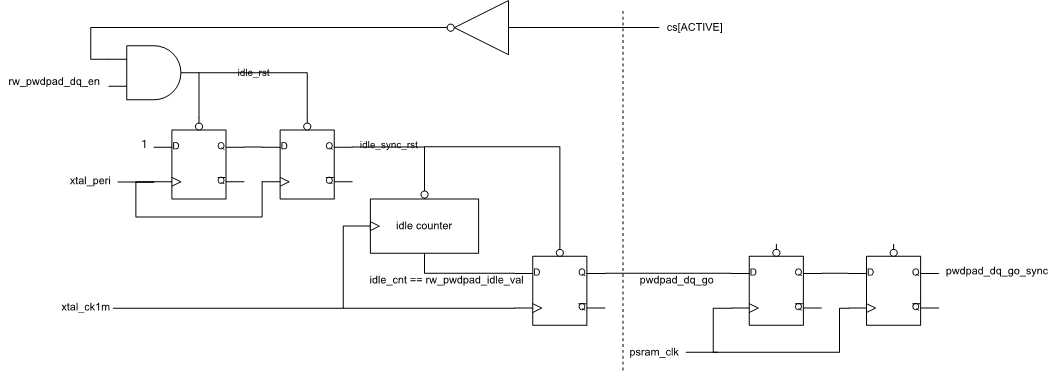
idle counter control logic
FSM

psram_axi_clutch state machine
psram_axi_clutch FSM state description is shown below.
State Name |
Description |
|---|---|
IDLE |
Check whether psram_auto_axi has access, axi signals go-through |
ACTIVE |
Psram_auto_axi has access, axi signals go-through |
STOP |
Shutdown psram DQ pads after idle counter reaching rw_pwdpad_idle_val |
RESUME |
Delay enough cycles for DQ pads resuming |
Waveform
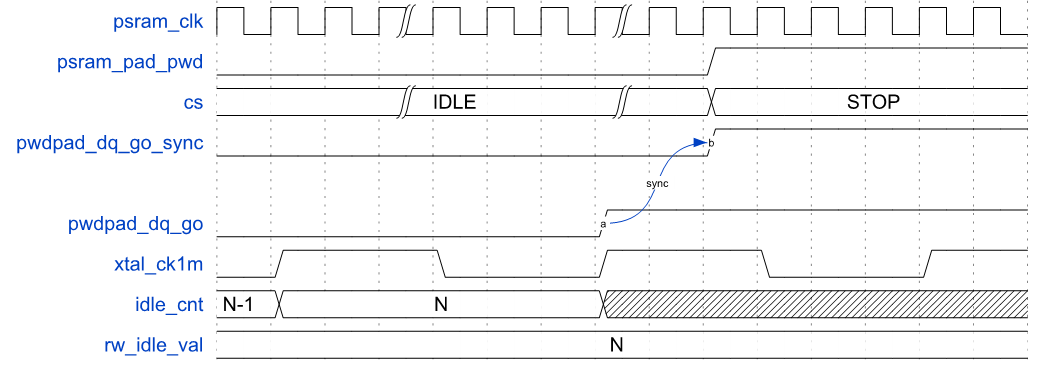
psram_axi_clutch entering STOP state
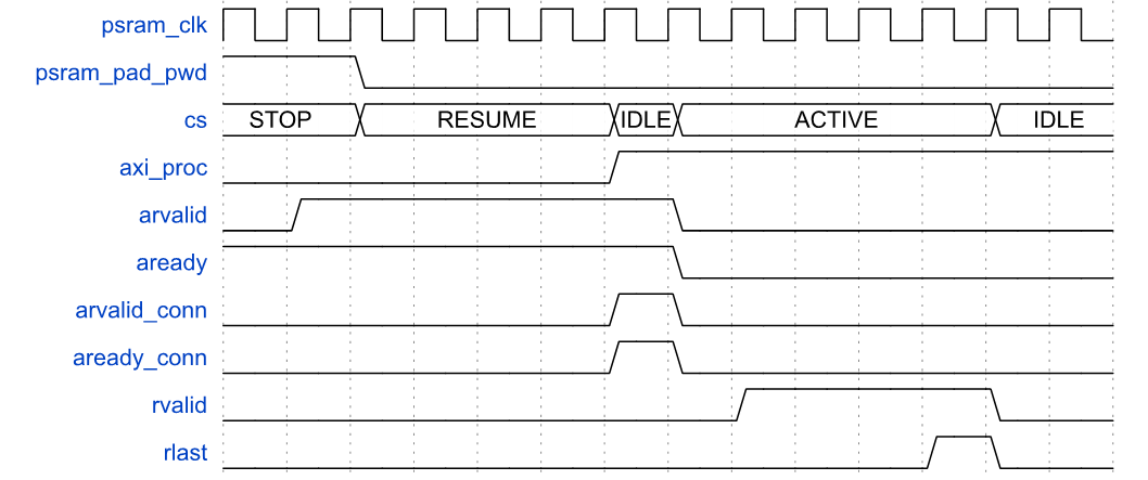
psram_axi_clutch resume
Corner Case and Exception
Design Flow Notes
Negedge clock.
Internal clock or reset.
Clock mux or clock gate.
False path or multcycle path.
Items to pay attention to in FPGA flow.