Ameba SoC uses a heterogeneous multi-core architecture, where system firmware consists of both MCU and DSP firmware.
DSP and MCU share Flash and memory resources. Before building firmware, you must plan the Flash partitioning and Memory Layout (SRAM, PSRAM, and IPC shared memory) in advance, which is the foundation for proper collaboration between the two.
Users can choose different firmware packaging and flashing methods at different stages:
Firmware Type
Filename
Applicable Stage
Functional Description
Bootloader
km4_boot_all.bin
Universal
System boot loader, responsible for loading MCU and DSP firmware.
DSP Standalone Firmware
dsp_all.bin
Development Stage
Standalone DSP firmware with header information, can be directly flashed to the DSP partition of Flash.
MCU Standalone Firmware
kr4_km4_app.bin
Development Stage
Contains only MCU application firmware. DSP firmware is flashed separately, the two are decoupled.
DSP Raw Firmware
dsp.bin
Production Stage
Pure binary code, must be copied to MCU SDK and merged as a sub-firmware into the complete MCU firmware.
MCU DSP Unified Firmware
kr4_km4_dsp_app.bin
Production Stage
All-in-One application firmware. MCU firmware has DSP firmware embedded, supports overall OTA upgrade and secure boot.
Ameba SDK supports two build methods: Separate Packaging is suitable for development debugging; Merged Packaging is suitable for final production release.
The following diagram shows the complete process from source code compilation to firmware generation:
Based on the project stage, please select the appropriate mode:
Development Stage: Separate Packaging Mode
Features: DSP and MCU firmware files are separated, flashed to different Flash addresses respectively.
Advantages:
Fast debugging: After modifying DSP algorithms, only the smaller dsp_all.bin needs to be compiled and re-flashed, no need to rebuild MCU.
Decoupled: Suitable for DSP algorithm engineers to develop independently, without relying on MCU code base.
Operation: Disable DSPwithinAPP option in MCU SDK Menuconfig.
Production Stage: Merged Packaging Mode
Features: DSP firmware and MCU firmware are concatenated to generate a single file.
Advantages:
Supports OTA: During system upgrade, MCU and DSP are updated as a whole version atomically, ensuring compatibility.
Supports Secure Boot: DSP firmware can be verified through MCU’s Secure Boot, providing higher security.
Operation:
Must copy dsp.bin to the specified directory in MCU SDK.
Enable DSPwithinAPP option in MCU SDK Menuconfig.
The following sections describe configuration details and operation methods:
First, build the DSP firmware. The DSP SDK provides two build methods. Please choose according to your development environment.
Method 1: Command Line Build (Linux):
Applicable scenarios: Linux servers, automated build workflows, when project configuration is difficult to modify.
1. Environment Preparation
Before using scripts to build the project, you must add the Xtensa toolchain path to the system environment variable PATH.
# Example path (please adjust according to actual installation location)exportPATH=$PATH:/opt/xtensa/XtDevTools/install/tools/RI-2021.8-linux/XtensaTools/bin
2. Build Configuration
The automatic build script determines build parameters by reading the project/auto_build/dsp_batch.xml file. Please open this file and select the appropriate Configuration according to project requirements:
HIFI5_PROD_1123_asic_wUPG (Window ABI): Suitable for scenarios where code and data are located within the same 1GB address space.
HIFI5_PROD_1123_asic_UPG (Call0 ABI): Suitable for scenarios involving cross-memory function calls (e.g., jumping between SRAM and PSRAM).
For in-depth technical details about ABI, please refer to
DSP ABI Selection
.
3. Execute Build
Navigate to the automatic build directory and run the script:
Workspace Reset Warning: This script automatically creates a temporary workspace named auto_ws and copies project_dsp into it for building.
Do not modify code in the auto_ws directory, as it will be cleared and overwritten the next time the script runs. All code modifications should be made in the original project_dsp directory.
4. Verify Output
After a successful build, the firmware is stored at the following path:
Output directory: <dsp_sdk>/project/image/
Key files:
dsp_all.bin (for development stage flashing)
dsp.bin (for production stage merging)
Method 2: Xplorer GUI Build (Windows/Linux):
Applicable scenarios: Windows environment, or when modifying project configuration.
1. Environment Preparation
Xtensa toolchain: Must add the path to the system environment variable PATH.
Python environment: Ensure Python (3.8+) is installed and added to environment variables.
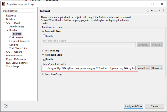
Tip
If your system command is python3 instead of python, please adjust the command to python3 in the Post-build step of the project properties (as shown in the red box in the figure below).
2. Import Project
Open Xtensa Xplorer and set Workspace to <dsp_sdk>\project.
Click menu File > Import, select General > Existing Projects into Workspace.
Regardless of the packaging mode, the MCU must adjust the memory layout to accommodate DSP operation.
SRAM is faster than PSRAM. To accelerate DSP calculations, the default SDK allocates most of the SRAM to the DSP.
Therefore, the MCU data segment must be relocated to PSRAM.
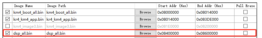
Corresponds to the separate packaging mode mentioned above. In this mode, there is an independent DSP partition in Flash, requiring two files to be flashed separately. Flashing list:
Firmware File
Target Partition (Flash Layout)
Description
km4_boot_all.bin
IMG_BOOT
Bootloader
kr4_km4_app.bin
IMG_APP
MCU application
dsp_all.bin
IMG_DSP
DSP complete firmware (with Header)
Warning
This mode does not support OTA upgrades and firmware tamper verification. It is intended for laboratory development only.
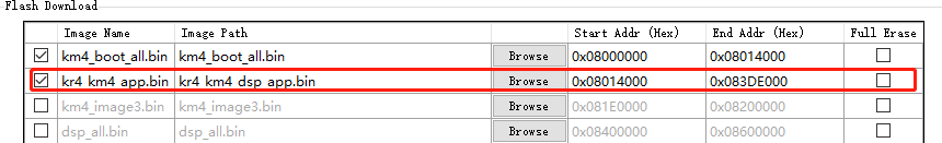
Development Phase (Merged Flashing):
Corresponds to the merged packaging mode mentioned above. In this mode, DSP firmware is embedded within the MCU firmware, requiring only one file to be flashed. Flashing list:
After completing the flashing, please press the reset button to restart the development board and view logs through the UART serial tool.
Check Boot Logs:
Observe whether DSP initialization-related prints appear.
Verify Success Indicators:
Under normal circumstances, you should see output similar to the following:
Hello DSP World
Since KM4, KR4, and DSP cores share the same physical serial output, logs may be interleaved.
It is recommended to add specific prefixes (such as [DSP]) to print messages in DSP code, or use multi-line printing to facilitate differentiation and debugging.
Disassembly files translate machine code back to assembly language, used for low-level code analysis and Crash localization.
The SDK disables disassembly generation by default. To enable it, follow these steps:
Open the post-processing script: <dsp_sdk>/project/img_utility/code_analyze.py
Find the configuration option ENABLE_Disassembler and change it to 1:
# User ConfigurationENABLE_Disassembler=1# 0: Disable (Default), 1: Enable
Re-execute the compilation process. Disassembly file locations:
Map files record the runtime addresses of symbols (functions, variables) and the size of each section in detail, making them a powerful tool for analyzing firmware structure and troubleshooting address errors. Map file locations: